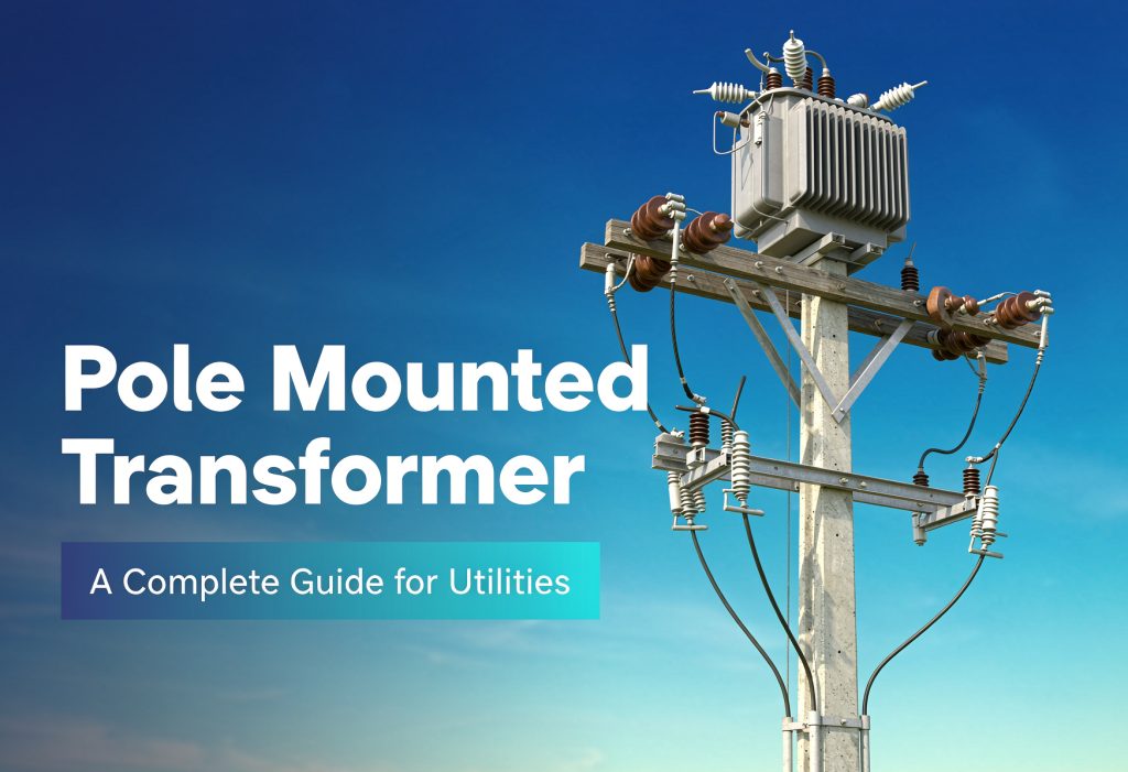
A pole mounted transformer is a liquid-filled distribution transformer hung on a utility pole that steps primary distribution voltage — typically 7,200 V to 34,500 V — down to the 120/240 V service voltage customers actually use. In North American practice, single-phase units run 10 kVA to 333 kVA, and a 50 kVA unit measures roughly 25 × 27 × 41 in and weighs about 871 lb filled. Specifying one comes down to six decisions: kVA, primary voltage, secondary voltage, conventional vs CSP protection, efficiency tier, and insulating fluid. Everything else is detail.
Here’s the thing most guides won’t say out loud: the transformer is rarely the hard part. The hard part is whether the pole will carry it, whether the mounting height clears the road, and whether the unit you ordered is legal to import on the day it shows up. This guide covers all three, with the numbers attached.
The 60-second version
If you only read one section, read this one.
- “Pole mounted” describes the mounting, not the product. The transformer is a distribution transformer; the pole is just where it hangs. That distinction matters because the standard that governs it — IEEE C57.12.20-2023 — caps overhead-type distribution transformers at 500 kVA, high voltage 34,500 V and below, low voltage 7,970/13,800Y V and below.
- Single-phase is the default. Standard ratings run 10, 15, 25, 37.5, 50, 75, 100, 167, 250, and 333 kVA. Ordering 120 kVA buys you a custom unit, a longer wait, and a higher price for no benefit.
- Weight decides the structure before kVA does. A 50 kVA unit is about 871 lb filled; a 167 kVA unit is about 1,499 lb. Most utilities move off single-pole mounting somewhere in that range.
- Conventional vs CSP is the first real fork. Conventional puts the fuse, arrester, and secondary breaker on the pole. CSP puts all three inside the tank. Budget roughly +10–20% for CSP, and expect fewer pole-top parts to inspect.
- Size from demand, not from connected load. Apply a diversity factor before you divide by power factor. Skipping it can inflate your kVA by 30–60%, and you pay for that mistake twice — once in the purchase price, then every hour afterward in no-load losses.
- US efficiency is a legal floor with a date on it. Compliance tightens April 23, 2029, and the date that matters is when the unit was manufactured or imported — not when you signed the PO.
- “Meets DOE 2029” is meaningless without the kVA attached. The 2029 curve is not monotonic: a 300 kVA three-phase unit is held to 99.42% while a 500 kVA unit is held to only 99.38%. A bigger transformer is allowed to be less efficient than a smaller one.
- The 2029 rules are not frozen. DOE published a Request for Information on June 15, 2026 (91 FR 114, docket EERE-2026-BT-STD-0133) asking whether the 2029 standards create supply-chain and hardship problems. The levels can still move.
- Mounting height is an NESC question, not an NEC one. If a guide tells you “NEC Article 450 requires 18 feet,” it has the wrong code. Overhead clearance lives in NESC Rule 232 — and Rule 232B explicitly covers equipment mounted on supporting structures.
- Plan the lead time before you plan the outage. Published lead times in 2026 run from about 6–10 weeks for a stocked catalog unit to well over a year for a backlogged utility-spec build. Same product category, roughly a 6× spread.
What a pole mounted transformer actually is
A pole mounted transformer is a distribution transformer installed above ground on a utility pole or engineered pole structure, stepping primary distribution voltage down to customer service voltage. It is liquid-immersed and self-cooled in virtually every North American application, and it may serve single-phase or three-phase loads depending on its design and connections.
The nickname you’ll hear in the field is pole pig. It’s fine in conversation and useless in a specification — a nickname can’t tell a supplier what phase, rating, BIL, or protection package you need.
Three terms get shuffled around and they aren’t interchangeable:
- Distribution transformer — the functional role (steps distribution voltage down to utilization voltage).
- Pole mounted / overhead / pole-top — the mounting arrangement.
- Conventional / CSP — the protection arrangement.
All pole mounted transformers are distribution transformers. Not all distribution transformers are pole mounted. If your application ends up underground instead, that’s a different animal entirely.
One more boundary worth drawing: a pole mounted transformer changes voltage. A pole mounted recloser, regulator, or switch does something else. They share real estate on the pole and they don’t share a spec sheet.
Almost every unit you’ll encounter is liquid-filled, for a boring and correct reason: at these ratings, oil is the cheapest way to get heat out of a sealed can hanging in the sun. If you want the full argument for liquid versus air, our breakdown of oil-immersed distribution transformers covers where the choice actually flips.
Conventional vs CSP: the first spec decision
This is the fork that determines what else shows up on the pole, and it’s cheaper to decide now than to retrofit.
| Conventional | CSP (completely self-protected) | |
| Primary fault protection | External fused cutout on the pole | Internal protective link in series with the HV winding |
| Surge protection | Externally mounted arrester | Arrester mounted on the tank |
| Secondary protection | Separate secondary breaker | Internal secondary breaker in the tank |
| Fault indication | Visual (open cutout) | Signal light + external operating handle with overload reset |
| Pole-top hardware count | Higher | Lower |
| Field replacement | Replace components individually | Replace the transformer |
| Typical upcharge | Baseline | Roughly +10–20% |
The trade is honest in both directions. Conventional gives you individually replaceable parts — blow a fuse, replace a fuse. CSP gives you fewer things to inspect and a cleaner pole, but an internal fault means the whole unit comes down.
New construction skews CSP. Retrofits into an existing protection scheme usually stay conventional. Either way, confirm with the serving utility — this is their call, not yours.
Single-phase, three-phase, and banks
Single-phase is the workhorse: residential neighborhoods, rural taps, farms, irrigation pumps, small commercial. Standard ratings run 10 kVA to 333 kVA, and the secondary is a center-tapped winding giving 120/240 V — 120 V from either half to neutral, 240 V across the full winding.
One trap worth naming: you cannot draw the full kVA from one 120 V half-winding. A 50 kVA unit delivers 208 A at 240 V; it does not deliver 416 A at 120 V.
Three-phase pole units serve commercial and light industrial loads where the customer needs 120/208Y or 277/480Y. They run roughly 15 kVA to 500 kVA and they are heavy enough that they normally sit on a platform across two poles rather than hanging off one.
A bank is three single-phase units connected to serve a three-phase load. Utilities do this constantly because it keeps the spare pool to one product. The common connections are closed wye, open wye (two units), and open delta (two units) — and the open configurations deliver less than the sum of the nameplates, which is where a lot of sizing errors come from.
The winding construction on single-phase overhead units is usually cylindrical, and it’s worth understanding what that implies before you read a cut sheet. We go through it in detail on our page for single-phase cylindrical-winding transformers.
Ratings: kVA, voltage, BIL, impedance
Four numbers, and all four belong on the RFQ.
1. kVA rating. Buy a standard rating. Deviating buys you a custom design, a longer lead time, and a premium.
2. Primary voltage. Match the nominal voltage at the tap point. Common North American classes: 2,400 / 4,160 / 7,200 / 12,470 / 13,200 / 13,800 / 19,920Y / 34,500GrdY V. Getting this wrong ruins your tap settings and your insulation coordination at the same time.
3. Secondary voltage. 120/240 V single-phase, or 120/208Y and 277/480Y three-phase.
4. BIL and impedance. BIL (basic impulse insulation level) has to match the system insulation level — specify it, don’t assume it. Impedance for overhead distribution units typically lands in the low single digits as a percentage; it sets available fault current and it has to coordinate with your fusing.
| Parameter | What to specify |
| kVA | Standard rating at or above calculated demand |
| Primary voltage | Match the utility’s distribution class at the tap point |
| Secondary voltage | 120/240 V (1-ph) or 120/208Y / 277/480Y (3-ph) |
| BIL | Match system insulation level — don’t leave it blank |
| Impedance | Typically low single digits %; must coordinate with fusing |
| Taps | Usually 4–5 positions, up to ±5%; de-energized operation only |
| Cooling | ONAN (self-cooled) — standard for overhead units |
| Frequency | 60 Hz for North America |
If you’re specifying for export or comparing an IEC design against an ANSI one, the naming conventions diverge in ways that cause real procurement errors. Our comparison of IEC 60076 vs ANSI/IEEE standards walks through it.
Sizes and weights: what actually fits on a pole
This is the section every other guide on this topic skips, and it’s the one that decides whether your design survives contact with a structures engineer.
Typical catalog values for single-phase overhead units, conventional construction:
| Rating | Width | Depth | Height | Filled weight |
| 10 kVA | 500 mm (19.7 in) | 525 mm (20.7 in) | 885 mm (34.8 in) | 150 kg (331 lb) |
| 15 kVA | 520 mm (20.5 in) | 565 mm (22.2 in) | 905 mm (35.6 in) | 210 kg (463 lb) |
| 25 kVA | 560 mm (22.0 in) | 590 mm (23.2 in) | 935 mm (36.8 in) | 258 kg (569 lb) |
| 37.5 kVA | 610 mm (24.0 in) | 625 mm (24.6 in) | 935 mm (36.8 in) | 340 kg (750 lb) |
| 50 kVA | 635 mm (25.0 in) | 675 mm (26.6 in) | 1,035 mm (40.7 in) | 395 kg (871 lb) |
| 75 kVA | 745 mm (29.3 in) | 840 mm (33.1 in) | 1,035 mm (40.7 in) | 480 kg (1,058 lb) |
| 100 kVA | 770 mm (30.3 in) | 965 mm (38.0 in) | 1,135 mm (44.7 in) | 530 kg (1,169 lb) |
| 167 kVA | 795 mm (31.3 in) | 890 mm (35.0 in) | 1,335 mm (52.6 in) | 680 kg (1,499 lb) |
| 250 kVA | 1,080 mm (42.5 in) | 1,030 mm (40.6 in) | 1,390 mm (54.7 in) | 1,280 kg (2,822 lb) |
| 333 kVA | 1,140 mm (44.9 in) | 1,060 mm (41.7 in) | 1,450 mm (57.1 in) | 1,550 kg (3,417 lb) |
Typical manufacturer catalog values for single-phase overhead units. Confirm against the certified outline drawing for the unit you’re actually buying before you design the structure or book the crane.
Two things fall out of this table.
Weight drives the structure. Rough practice, subject to your utility’s construction standard:
| Filled weight | Commonly seen structure |
| Up to ~900 lb (≤ 50 kVA) | Single pole, crossarm or direct-mounted |
| ~1,000–1,500 lb (75–167 kVA) | Heavy-class single pole, or two-pole H-frame depending on utility practice |
| ~2,800–3,400 lb (250–333 kVA) | Two-pole H-frame or platform mount |
| Three-phase, any rating | Platform across two poles |
Weight also drives the crane. A 333 kVA unit at 3,417 lb is a different lift than a 50 kVA unit at 871 lb. And here’s the trap: retail price tables publish weights that don’t match filled catalog weights. One US distributor’s 2026 pole transformer price table lists a 167 kVA unit at 800–1,100 lb; the filled catalog weight is closer to 1,499 lb. Rig from the certified drawing, never from a price sheet.
How to size one: 4 steps with a worked example
Step 1 — Total up the connected load. Everything that could be on at once, in kVA.
Step 2 — Apply a diversity factor. Not everything runs simultaneously. Residential work commonly lands in the 0.5–0.8 band depending on the customer mix.
Step 3 — Divide by power factor if you’re working from kW rather than kVA.
Step 4 — Add growth margin, then round up to a standard rating. 20–25% is typical.
Worked example — 12 homes at 5 kVA each:
- Connected: 12 × 5 = 60 kVA
- Diversity factor 0.6: 60 × 0.6 = 36 kVA
- Growth margin 25%: 36 × 1.25 = 45 kVA
- Round up to standard: 50 kVA
Skip step 2 and you’d order 75 kVA. That’s 50% more purchase price, and permanently higher no-load losses for the 30-plus years the unit sits on that pole.
How many homes does one pole transformer serve?
Published planning ranges from a US distributor:
| Transformer size | Homes served | Typical setting |
| 25 kVA | 2–4 | Rural, low density |
| 50 kVA | 5–10 | Suburban residential |
| 75 kVA | 10–15 | Dense suburban |
| 100 kVA | 15–25 | Urban residential |
| 167 kVA | 25–40 | Subdivision, school |
| 250 kVA | 40+ | Large subdivision, light commercial |
Indicative planning ranges from one US distributor’s published 2026 table; treat as a starting point, not a design basis.
The honest answer is that kVA alone can’t give you a house count — you need per-home demand and a diversity assumption. But there’s a second constraint people forget: utilities commonly plan to 50–60% loading, which reserves headroom for peak demand and load growth. A 50 kVA unit that could theoretically serve 10 homes is often deployed on 6.
And one load is changing the math fast: EV charging. A single Level 2 charger adds 7–19 kVA that wasn’t in the original diversity calculation. Before you upsize, check whether the load is clustered on a few services.
Efficiency: what changes on April 23, 2029
DOE’s April 2024 final rule (89 FR 29834) amended the distribution transformer standards. It took effect July 8, 2024; compliance with the amended levels is required for units manufactured or imported on or after April 23, 2029.
Three things matter:
- The trigger is the manufacturing or import date — not your PO date, not your delivery date. A unit built in late 2028 and delivered in 2029 is judged on the old table.
- Nothing requires you to replace installed equipment. This governs what can be made and imported.
- Coverage expands. Ratings above 2,500 kVA were outside federal scope; from 2029, coverage reaches 5,000 kVA.
Minimum efficiency, single-phase liquid-immersed — the ratings that matter for pole mounted units — at 50% load (10 CFR 431.196):
| kVA | Manufactured before 4/23/2029 | Manufactured on or after 4/23/2029 |
| 10 | 98.70% | 98.77% |
| 15 | 98.82% | 98.88% |
| 25 | 98.95% | 99.00% |
| 37.5 | 99.05% | 99.10% |
| 50 | 99.11% | 99.15% |
| 75 | 99.19% | 99.23% |
| 100 | 99.25% | 99.29% |
| 167 | 99.33% | 99.46% |
| 250 | 99.39% | 99.51% |
| 333 | 99.43% | 99.54% |
| 500 | 99.49% | 99.59% |
Note the step at 167 kVA: the requirement jumps 0.17 percentage points between 100 and 167 kVA, while every other step is 0.04–0.07. That’s where the economics of core material change, and it’s the rating band where you should expect amorphous core to become the default answer.
For three-phase pole mounted units:
| kVA | Manufactured before 4/23/2029 | Manufactured on or after 4/23/2029 |
| 15 | 98.65% | 98.92% |
| 45 | 98.92% | 99.14% |
| 75 | 99.03% | 99.22% |
| 150 | 99.16% | 99.33% |
| 225 | 99.23% | 99.38% |
| 300 | 99.27% | 99.42% |
| 500 | 99.35% | 99.38% |
Look at the right-hand column between 300 and 500 kVA. It goes down. A 300 kVA unit is held to 99.42% while a 500 kVA unit is held to only 99.38%. The curve steps backward again between 2,500 and 5,000 kVA.
So: “Meets DOE 2029” is a meaningless claim without the kVA attached. Ask for certified no-load and load loss values at your specific rating, not a compliance sentence on a cut sheet.
What’s not covered — and why that cuts both ways
The federal definition of a covered distribution transformer requires input 34.5 kV or less, output 600 V or less, 60 Hz operation, and a rating of 10–2,500 kVA for liquid-immersed units. A lot of pole mounted units fall outside it:
- Secondary above 600 V — a pole unit feeding a 2,400 V or 4,160 V irrigation pump isn’t covered.
- Tap range of 20% or more.
- Step-up duty — the output is above 600 V, so it’s outside the definition.
- Also excluded: autotransformers, drive (isolation) transformers, grounding transformers, rectifier transformers, UPS transformers, welding transformers, sealed and non-ventilated transformers, special-impedance and regulating transformers, and testing transformers.
Also note the ceiling interaction: IEEE C57.12.20 caps overhead-type distribution transformers at 500 kVA. So the 3,750 kVA and 5,000 kVA rows that appear in the 2029 table can never apply to a pole mounted unit. If a supplier cites those rows at you, they’re padding.
One arithmetic check worth doing
Here’s a gap that never shows up on a cut sheet. Take a published export catalog’s 50 kVA single-phase figures: 135 W no-load, 500 W load loss. Run it on the DOE basis — 50% load, 25 kW output:
- Losses at 50% load = 135 + (500 × 0.5²) = 135 + 125 = 260 W
- Efficiency = 25,000 / (25,000 + 260) = 98.97%
The federal floor for 50 kVA is 99.11%. That’s a 0.14-point miss, and it would never surface from a sheet that only prints “Efficiency: 99%.” Illustrative calculation from one catalog’s published loss figures; always require certified loss values from the supplier.
Are the 2029 rules final? The 2026 RFI
Short answer: the compliance date is set, the levels are not necessarily frozen.
On June 15, 2026, DOE published a Request for Information in the Federal Register (91 FR 114, docket EERE-2026-BT-STD-0133), with comments due July 15, 2026. It follows a Presidential Determination issued April 20, 2026 finding that grid infrastructure supply chains — including distribution transformers and electrical core steel — are essential to national defense, and that US industry faces “limited domestic product capacity, extended procurement timelines, and foreign supply dependence.”
DOE explicitly asked whether the revised standards create special hardship, inequity, or unfair distribution of burdens, including the investment needed to redesign equipment for the 2029 date.
What this means for you practically:
- Don’t lock a 20-year fleet standard to the 2029 numbers without a re-check clause. Re-verify current eCFR text before any multi-year contract.
- An RFI is not a final rule. Nothing has changed yet. But it’s a signal that the levels are under active review, and no competitor page on this topic mentions it.
- The supply picture is part of the rulemaking now. That’s unusual, and it tells you lead times are a policy concern, not just a purchasing one.
No-load vs load loss: where the money actually is
Two loss buckets behave completely differently, and mixing them up is how people buy the wrong upgrade.
- No-load (core) loss runs 24 hours a day, 8,760 hours a year, whether anyone is using power or not.
- Load (winding) loss scales with the square of the load. At half load it’s a quarter of nameplate.
Worked example — 50 kVA single-phase, 135 W no-load, 500 W load loss, $0.13/kWh:
| Average load | Core loss | Winding loss | Total | Annual cost | Which dominates |
| 30% | 1,183 kWh/yr | 394 kWh/yr | 1,577 kWh/yr | ~$205 | Core: 75% |
| 75% | 1,183 kWh/yr | 2,464 kWh/yr | 3,647 kWh/yr | ~$474 | Windings: 68% |
Illustrative calculation. Assumptions: 135 W no-load, 500 W load loss, 8,760 h/yr, $0.13/kWh, flat load profile.
Bottom line: if your transformer sits at 30% most of the time, buy a better core. If it runs at 75%, buy heavier conductor. Ordering a copper winding upgrade on a lightly loaded residential unit is paying for capacity you will never use — and pole mounted transformers, especially residential ones, spend most of their lives lightly loaded.
That’s precisely why the 2029 step at 167 kVA matters: it’s the band where core material starts driving the compliance answer. If you’re specifying into that range, it’s worth understanding what amorphous-alloy designs actually change and where the claims break down — and more broadly, what low-loss transformer design does and doesn’t buy you.
Standards that apply — and the one people cite wrong
The standards that genuinely govern a North American pole mounted transformer:
| Standard | What it covers |
| IEEE C57.12.20-2023 | Overhead-type distribution transformers, 500 kVA and smaller, HV ≤34,500 V, LV ≤7,970/13,800Y V, single- and three-phase, 60 Hz, liquid-immersed, self-cooled |
| IEEE C57.12.31-2020 | Pole-mounted equipment — enclosure integrity |
| IEEE C57.12.30-2020 | Pole-mounted equipment — enclosure integrity for coastal environments |
| IEEE C57.12.90 | Test code for liquid-immersed distribution, power, and regulating transformers |
| IEEE C57.12.00 | General requirements for liquid-immersed distribution, power, and regulating transformers |
| NESC (IEEE C2) | Clearances, pole loading, grounding for supply stations and equipment |
C57.12.31 and C57.12.30 are the pole-mounted equivalents of the pad-mount enclosure-integrity standards everybody quotes. They’re how you specify that a coastal unit won’t rust through in eight years. Almost nobody on this topic mentions them.
The one people cite wrong
Mounting height and clearances are NESC, not NEC. Plenty of guides — including a well-ranked 2026 page — state that “NEC Article 450” sets the height of a transformer above ground. It doesn’t. NEC Article 450 is the transformer article of the National Electrical Code and it addresses installation, guarding, and accessibility. It does not set overhead clearances for equipment on a utility pole.
Those live in the National Electrical Safety Code (NESC, IEEE C2):
- Rule 232 — vertical clearance of wires, conductors, cables, and equipment above ground, roadway, rail, or water surfaces. Rule 232B specifically addresses equipment mounted on supporting structures.
- Rule 232C — voltage adder above 22 kV: 0.40 in per kV for each kV in excess of 22 kV.
- Rule 234 — clearance from buildings, bridges, rail cars, swimming pools, and other installations.
Commonly applied Table 232-1 values for open supply conductors in the 750 V–22 kV band:
| Surface underneath | Commonly applied clearance |
| Roads, streets, alleys, areas subject to truck traffic | 18.5 ft |
| Driveways, parking lots, alleys | 18.5 ft |
| Spaces and ways subject to pedestrians or restricted traffic only | 14.5 ft |
| Along roads, not overhanging | 18.5 ft |
NESC-derived values; confirm against the current NESC edition and the serving utility’s construction standard, which governs in practice. Add 0.40 in per kV above 22 kV per Rule 232C.
Two practical notes. First, that 18.5 ft figure is a conductor clearance — and it’s where the “18 feet” in a lot of pole transformer content actually comes from, mis-attributed to NEC. Second, your utility’s construction standard is the document the crew builds to. NESC is the floor; utility standards are usually stricter.
Protection: what’s on the pole and what’s inside the tank
Regardless of conventional or CSP, four protective functions need to exist somewhere:
- Primary overcurrent protection — fused cutout (conventional) or internal protective link (CSP). It clears internal faults so a failed transformer doesn’t take the feeder down.
- Surge protection — metal-oxide arresters on the primary side. Lightning is the leading cause of transformer failure in exposed overhead locations, and this is the single cheapest reliability dollar available.
- Secondary overcurrent protection — breaker or fused protection on the low-voltage side.
- Pressure relief — a self-resealing pressure relief device on the tank. This is what turns a slow internal fault into a venting event instead of a rupture.
Two upgrades worth asking about: wildlife guards on bushings and terminals (animal contact is a top-three failure cause on overhead systems), and current-limiting fuses where available fault current is high enough that a standard expulsion fuse won’t clear safely.
Anything that isn’t in the tank or on the pole by default is an accessory — and accessories have lead times too.
Installation: pole structure, mounting height, clearances
Sequence matters here, because three separate disciplines touch the same pole.
1. Structure. Pole class and condition have to carry the filled weight plus wind, ice, and the transformer’s own moment arm. This is where the weight table above earns its keep. NESC governs loading; the utility’s standard governs what gets built.
2. Mounting height. See the NESC discussion above. Confirm the vertical clearance over whatever is beneath the unit — roadway, driveway, pedestrian area — and remember that clearance applies at maximum sag, not at installation temperature.
3. Grounding. Tank, neutral, and arresters need a common grounding path with a low-resistance connection to earth. A transformer with good arresters and bad grounding is a transformer with bad arresters.
4. Phase and connection check before energization. Verify ratio, polarity, and that the secondary phasing matches the customer’s service. On a bank, this is where open-delta and open-wye mistakes surface.
What it costs, and why two quotes disagree 4×
One US distributor’s published 2026 ranges for single-phase pole mounted transformers:
| kVA | Price range (USD) | Typical application |
| 10 | $500 – $1,200 | Single home, irrigation pump |
| 25 | $1,200 – $2,500 | 2–5 homes, small farm |
| 50 | $2,500 – $4,000 | 8–15 homes, small business |
| 75 | $3,500 – $5,500 | 15–25 homes, commercial |
| 100 | $4,500 – $7,000 | 25–40 homes, light industrial |
| 167 | $7,000 – $12,000 | Large subdivision, school |
| 250 | $10,000 – $16,000 | Industrial facility |
| 333 | $14,000 – $22,000 | Manufacturing plant |
Indicative ranges from one US distributor’s published 2026 price table. Add roughly 10–20% for CSP and 15–30% for copper windings versus aluminum. Equipment only — installation, pole work, and commissioning are separate.
Now the interesting part. The highest-ranking guide on this topic publishes no prices at all — it explicitly declines, on the grounds that no reliable current market range covers all pole mounted transformers. Both positions are correct, and the gap between them is almost entirely scope:
| Variable | Effect on price |
| Commercial terms | EXW vs FOB vs delivered vs installed — the biggest single swing |
| Winding material | Copper +15–30% over aluminum |
| Protection package | CSP +10–20% over conventional |
| Efficiency tier | Higher-efficiency designs cost more up front, less over 30 years |
| Voltage class | Higher primary voltage = more insulation = higher cost |
| Fluid | Mineral oil vs natural ester vs high-fire-point fluid |
| Quantity and standardization | Utility-spec catalog units price very differently from one-offs |
| Testing and documentation | Extended routine tests, type tests, and certified loss reports add cost |
How to read a quote: normalize to the same boundary. A bare EXW number and a delivered-and-installed number aren’t two quotes for the same thing, and comparing them is the most common way utilities end up with a budget surprise.
Lead times and the 2026 supply picture
Published lead times for distribution transformers in 2026 span a range that looks like a typo:
- 6–10 weeks — advertised by at least one stocking manufacturer for catalog single-phase overhead units.
- Many months to over a year — utility-spec builds, large quantities, and anything requiring amorphous core or special-core steel. One government trade summary of the DOE RFI docket put distribution transformer backlogs at over 12 months as of early 2026, roughly double normal. (Indicative, second-hand; treat as directional.)
DOE’s own RFI notice confirms the direction without a number: US industry faces “extended procurement timelines.”
What to do about it:
- Standardize on catalog ratings. Custom kVA, custom taps, and custom bushings are where schedules go to die.
- Order against the manufacturing date, not the need date — especially across the April 23, 2029 boundary.
- Keep a spare pool sized to failure rate, not to budget. Storm damage, vehicle strikes, and lightning don’t respect procurement cycles.
- Ask where the core steel comes from. It’s now a named national-security supply chain, which means it’s a real schedule risk.
Testing and commissioning
Before a unit goes up, and again after:
- Ratio and polarity — confirms the windings are connected as specified.
- Winding resistance — catches bad joints and wrong conductor.
- No-load loss and exciting current — the number that tells you whether the core you paid for is the core you got.
- Applied and induced voltage tests — dielectric verification.
- Insulation resistance — the field check before energization.
- Leak / pressure test — a weeping tank becomes an environmental and fire problem.
Our full rundown of the routine tests every unit should pass covers what to require in the factory acceptance package and what to re-check in the field.
Reading the nameplate
The nameplate is the contract. Six fields do most of the work:
- kVA rating and whether it’s self-cooled or has a forced-cooled rating
- Primary and secondary voltage, plus the connection diagram
- BIL for both windings
- Impedance, as a percentage at a stated temperature
- Tap positions and the voltage at each
- Serial number — the one thing that ties the unit to its test report
The connection diagram is the field everyone skips and later regrets. It’s what tells a crew whether 120/240 V is available, and how. Full walkthrough: how to read a transformer nameplate and technical parameters.
Failure modes and warning signs
| Symptom | Common cause | What to do |
| Loud bang, then outage | Internal fault venting through the pressure relief device | Treat as energized-adjacent; isolate, do not approach |
| Sudden failure with burning smell | Lightning or surge damage | Check arrester condition and grounding |
| Steady 60 Hz hum | Normal magnetostriction of the core | No action — this is the sound of a working transformer |
| Louder or intermittent hum | Loose laminations, loose mounting | Inspect and torque; monitor |
| Crackling or popping | Internal arcing | De-energize immediately |
| Oil weeping at seams or bushings | Seal aging, overpressure, or tank corrosion | Sample and monitor; schedule replacement |
| Chronic low secondary voltage | Wrong tap position, overloaded unit, excessive line drop | Measure primary at the cutout, re-set tap |
| Repeated fuse operation | Overload, or fault current beyond the fuse rating | Re-check sizing and available fault current |
The steady hum is worth calling out because it generates a lot of unnecessary service calls: a transformer hums because the core physically vibrates at line frequency. That’s physics, not failure. Changing character — louder, intermittent, crackling — is the signal.
10 specification mistakes
- Specifying a non-standard kVA. Custom rating, custom lead time, custom price.
- Sizing from connected load with no diversity factor. Inflates kVA by 30–60%, and you pay for it in purchase price and no-load losses for 30 years.
- Leaving BIL blank. Invites a unit that doesn’t match the system insulation level.
- Assuming “DOE compliant” means 2029-compliant. Those are two different tables, and the trigger is a manufacturing date.
- Accepting an efficiency percentage instead of certified loss values. See the 98.97% vs 99.11% arithmetic above.
- Citing NEC 450 for mounting height. Wrong code; it’s NESC Rule 232.
- Rigging from a price table’s weight column. Published retail weights can be hundreds of pounds off filled catalog weight.
- Not specifying fluid type. Mineral oil, natural ester, and high-fire-point fluids have different fire codes, different environmental profiles, and different prices.
- Forgetting coastal or wildlife requirements. C57.12.30 and bushing guards are far cheaper as a factory option than as a retrofit.
- Ordering to the need date instead of the manufacturing date. The single easiest way to get caught by an efficiency change you didn’t plan for.
The RFQ pack
Send this and you’ll get comparable quotes on the first pass instead of the third.
For the wider context on vetting suppliers, factory audits, and what to ask before you sign, our distribution transformer buyer’s guide goes deeper.
Bottom line
Buy a standard kVA rating, match the utility’s primary voltage class, decide conventional vs CSP early, and demand certified loss values at your specific rating rather than a compliance sentence. Everything else on this page is there to keep one of those five things from going wrong.
Quick pick by application:
| Application | Typical rating | Protection | What to watch |
| Rural tap, 1–3 homes | 10–25 kVA | Conventional | Single-pole mount; verify pole class |
| Suburban cluster, 5–10 homes | 50 kVA | CSP | Diversity factor; EV load growth |
| Dense suburban, 10–20 homes | 75–100 kVA | CSP | Weight moves toward two-pole structure |
| Subdivision / school | 167 kVA | CSP | 2029 efficiency step at this rating; consider amorphous core |
| Farm / irrigation pump | 25–75 kVA | Conventional | Secondary above 600 V may fall outside DOE scope |
| Small commercial, 3-phase | 75–300 kVA | Conventional + external | Platform mount on two poles |
| Light industrial, 3-phase | 300–500 kVA | Conventional + external | C57.12.20 cap at 500 kVA; 2029 curve is non-monotonic here |
Frequently asked questions
What is a pole mounted transformer? A pole mounted transformer is a liquid-filled distribution transformer installed on a utility pole that steps primary distribution voltage — typically 7,200–34,500 V — down to customer service voltage, usually 120/240 V. “Pole mounted” describes the mounting arrangement, not a distinct product category.
How long does a pole mounted transformer last? Well-maintained overhead distribution transformers commonly deliver 30–40 years of service. Lightning exposure, sustained overloading, seal degradation, and corrosion all shorten that. Utilities typically budget replacement on a 30-year life, and plan loading so units aren’t run near nameplate continuously.
What’s the difference between a pole transformer and a distribution transformer? A pole transformer is a distribution transformer. “Distribution transformer” is the functional category — it also includes pad mounted, vault, and submersible units. “Pole mounted” describes where it’s installed. All pole transformers are distribution transformers; not all distribution transformers are pole mounted.
How much does a pole mounted transformer cost? Published 2026 US ranges run about 500–1,200 for 10 kVA up to 14,000–22,000 for 333 kVA, equipment only. Add roughly 10–20% for CSP protection and 15–30% for copper windings. Quotes vary widely mainly because of commercial scope — EXW, delivered, and installed are three different numbers.
Can you put a dry-type transformer on a pole? Practically, no. Dry-type distribution transformers are heavier per kVA at these ratings, need protection from direct weather, and aren’t covered by IEEE C57.12.20, which addresses liquid-immersed self-cooled overhead units. Pole mounted service is overwhelmingly liquid-filled.
What does CSP mean on a pole transformer? CSP means completely self-protected. The unit integrates a primary protective link, a tank-mounted surge arrester, and an internal secondary breaker with an external operating handle, overload reset, and signal light. It eliminates most pole-top protective hardware at roughly a 10–20% cost premium.
How many houses can one pole transformer supply? Published planning tables put 25 kVA at 2–4 homes, 50 kVA at 5–10, 100 kVA at 15–25, and 167 kVA at 25–40. The real answer depends on per-home demand and diversity, and utilities often plan to 50–60% loading to leave headroom for peaks and growth.
How high does a pole transformer have to be mounted? Overhead clearance is governed by the NESC, not NEC Article 450. NESC Rule 232B covers equipment mounted on supporting structures. Commonly applied Table 232-1 clearances for the 750 V–22 kV band are 18.5 ft over roads and driveways, 14.5 ft over pedestrian-only areas, plus 0.40 in per kV above 22 kV.
Why do pole transformers hum? The core physically vibrates at line frequency — 60 Hz in North America — due to magnetostriction. A steady low hum is normal. A hum that gets louder, becomes intermittent, or is accompanied by crackling or popping indicates a mechanical or electrical problem and should be investigated.
Do pole mounted transformers have to meet DOE efficiency rules? Most do. The federal definition covers 60 Hz units with input ≤34.5 kV, output ≤600 V, and ratings of 10–2,500 kVA liquid-immersed. Units with a secondary above 600 V (common for irrigation pumps), tap ranges of 20% or more, and step-up duty fall outside it.
What causes pole transformers to fail or explode? Lightning and surge damage, overloading, animal contact, aging insulation, and seal failure are the leading causes. Modern tanks carry self-resealing pressure relief devices that vent internal pressure rather than rupturing — which is why a loud bang is usually a protective device doing its job.
Who owns the transformer on my property? In most cases the serving utility owns and maintains it, even on private property, under an easement that grants access. Some commercial and industrial customers own their own transformers and are responsible for maintenance. If it’s on your property, ask the utility before anyone works near it.