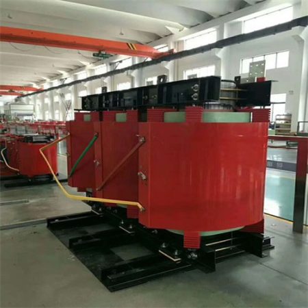
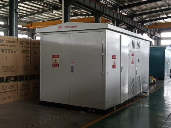
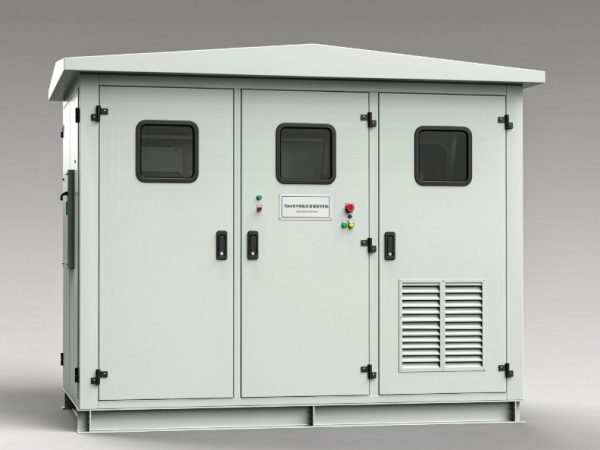
A low-loss power transformer is not a different machine — it is the same machine built with a better core steel grade, a tighter joint geometry, and a winding designed to keep stray losses down. The payoff is real but conditional: no-load loss is paid every hour of every year whether the transformer is loaded or not, while load loss is paid in proportion to the square of the load factor. This page separates the four design levers that genuinely move the numbers from the marketing wording around them, gives you the worksheet to compare two quotes on the same basis, and shows where “low-loss” quietly conflicts with “compact”, “quiet” and “cheap”. Every performance figure on this page that has not been verified against a type-test report is marked for confirmation — we would rather hand you a placeholder than a number you cannot defend in a bid.
Built and tested to IEC 60076-1/2/3, IEEE C57.12.00 and C57.12.90; efficiency claimed against GB 20052 (Chinese MEPS), DOE 10 CFR Part 431 Subpart K, or EU Ecodesign Regulation 2019/1783 — state which one applies on the RFQ.
1. What “Low-Loss” Actually Means in Numbers
A transformer has two loss components, and they behave completely differently.
| Component | Symbol | What causes it | When you pay it |
| No-load loss (core loss) | P0 | Hysteresis and eddy current in the core steel; fixed once the core is magnetised | 24 hours a day, 365 days a year, at any load including zero |
| Load loss (winding loss) | Pk | I²R in the windings plus eddy and stray loss in windings, clamps, tank walls | Scales with the square of the load factor |
Annual energy lost is:
Two consequences that drive every decision on this page:
- No-load loss is a fixed tax. 1 kW of no-load loss costs 8,760 kWh a year. At US
0.12/kWh that is about US1,051 a year, or roughly US$21,000 over a 20-year service life — before discounting. - Load loss is squared. 1 kW of load loss at a 0.6 load factor costs only 0.36 x 8,760 = 3,154 kWh a year, about US
378. At a 0.9 load factor it costs 7,100 kWh, about US852.
So the honest first question is not “how efficient is it?” but “what is my load factor?” A transformer that sits at 25 % load most of its life should be optimised almost entirely around no-load loss; one that runs at 85 % should be optimised around load loss, and no-load loss matters less.
There is also a peak-efficiency point worth knowing. Maximum efficiency occurs at beta = sqrt(P0 / Pk). For the illustrative 1,000 kVA unit in Section 11, that is about 0.33 — a useful sanity check when a supplier quotes a suspiciously low P0 and a high Pk, because it means the unit is only genuinely efficient in the bottom third of its range.
2. Where the Losses Come From
| Loss mechanism | Where it lives | Controlled by |
| Hysteresis | Core steel | Steel grade, grain orientation, domain refinement, thickness |
| Core eddy current | Core steel laminations | Lamination thickness, interlaminar insulation |
| Joint / corner loss | Core joints | Step-lap geometry, mitring, clamping pressure, whether the limb is punched |
| I²R (DC resistance) | Windings | Conductor cross-section, material (copper or aluminium), winding length |
| Winding eddy loss | Conductors | Strand dimensions, transposition (CTC), radial/axial conductor size vs leakage field |
| Stray loss | Clamps, frames, tank walls, bushing flanges | Magnetic shielding, non-magnetic or stainless inserts, distance from windings |
| Harmonic loss | Windings and structural parts | Load spectrum; K-factor rating under IEEE C57.110 or IEC 61378-1 |
Most brochures talk about the first two and stay silent on the last three. On a large unit the stray-loss term is a real and measurable part of total load loss, and it is where a “cheap” design quietly gives back the efficiency it claimed on the core.
3. Four Levers That Genuinely Move No-Load Loss
| Lever | What it does | Realistic effect | What to watch |
| Higher steel grade | Better grain orientation and lower specific loss (W/kg at 1.7 T, 50 Hz) | Grade-to-grade steps are typically [Confirm] percent per grade | Cost per kg rises; the mill certificate should be on file |
| Thinner laminations | Reduces core eddy current | [Confirm] percent moving to thinner gauge | Thinner gauge is more expensive and harder to stack cleanly |
| Domain-refined (laser-scribed) steel | Refines magnetic domains, cutting hysteresis | Typically quoted in the [Confirm] percent band | The refinement is produced by residual stress and can be erased by a later high-temperature stress-relief anneal. If the laminations are scribed, the downstream process window must be respected — ask for the mill’s guidance in writing |
| Lower flux density | Moves the operating point down the B-H curve | Loss falls roughly with the square of flux density | Requires a larger core cross-section — more steel, more copper, more weight, larger footprint. This is the direct conflict with “compact” |
Two more that are often listed but rarely specified: joint geometry (step-lap mitred joints, no punched holes through the limb — every hole distorts flux locally and adds loss and noise) and stress-relief annealing after cutting and stacking, which recovers the loss performance damaged by slitting and shearing. For grain-oriented silicon steel the anneal atmosphere and temperature should be confirmed with the maker; for amorphous alloy the thermal treatment is different again, because amorphous core is annealed under a magnetic field. Both details are worth a [Confirm] in your specification rather than an assumption.
4. Wound Core vs Stacked Step-Lap Core
The source material describes a wound (continuously wound strip) core. That is a legitimate low-loss construction, but it is not the only one, and the two behave differently.
| Wound core (continuous strip) | Stacked step-lap core | |
| Joints at corners | No discrete corner joints; the flux path is continuous | Step-lap mitred joints, repeated every layer |
| Typical no-load loss | Lower for a given grade, because the joint contribution is removed | Slightly higher, narrowed a lot by good step-lap geometry |
| Stacking / build factor | High effective section | High, depends on stacking discipline |
| Repairability | Effectively zero: a damaged wound core is not rewound in the field | Repairable: laminations can be restacked |
| Best fit | Distribution ratings, sealed units, long production runs | Medium and large power transformers, anything that may need repair |
Worth saying plainly: a well-executed step-lap stacked core with modern domain-refined steel is close to a wound core on loss. The gap that marketing copy describes as decisive is often a few percent once both designs use the same steel grade. Ask for the guaranteed P0 for the exact rating you are buying — not a range, and not a comparison against a different core type.
5. Claims About Low-Loss Designs: What Holds Up, What Needs Rewording
| Common claim | Assessment | How to word it so it survives a bid review |
| “Low loss, high efficiency” | Meaningless without a reference | State P0 and Pk in W, at a stated reference temperature, against a stated standard (GB 20052, DOE, EU Ecodesign) |
| “Seamless core, higher stacking factor, larger effective section” | Holds up for wound core | Say “wound core with no corner joints”; do not imply stacked cores cannot be low-loss |
| “Vacuum annealed” | Needs checking | Grain-oriented steel is stress-relief annealed after cutting; amorphous is field-annealed. Confirm the atmosphere and temperature with the maker, and confirm it is compatible with any domain-refined steel |
| “Low noise” | Partly true, partly a separate discipline | Noise comes from magnetostriction, joint quality, clamping and tank resonance. A low-loss core is not automatically quiet; see Section 8 |
| “Small footprint” | In tension with the loss claim | Lower loss at the same rating usually means lower flux density, which means more steel and copper. See Section 9 |
| “Sealed, so the oil never contacts air” | True, and it has a protection consequence | See Section 7 — a hermetically sealed unit has no gas path, so a Buchholz relay cannot be fitted |
| “Maintenance-free” | Overstated | Sealed construction removes oil sampling, filtration and the conservator breather. It does not remove terminal checks, IR testing, cooling surface cleaning, or protection testing |
6. Windings: Where Load Loss Is Won or Lost
Load loss is where two quotes that look identical on the core diverge.
- Conductor material. Copper gives lower resistance per cross-section and better short-circuit and thermal behaviour; aluminium reduces material cost and weight. Copper windings are commonly quoted at a [Confirm] percent price premium. Whichever you choose, write it into the specification — “copper” or “aluminium”, not “conductor of adequate cross-section”.
- Conductor form. Flat copper conductor, and on larger ratings continuously transposed cable (CTC), cut winding eddy loss by subdividing the conductor in the leakage field. The source material’s “cylindrical” and “continuous” winding forms are both standard; disc (continuous) windings are the norm where axial short-circuit forces are high.
- Short-circuit strength. IEC 60076-5 and IEEE C57.12.90 are the acceptance references. A design pushed to the minimum on copper will pass the loss guarantee and fail the short-circuit test — which is a far more expensive failure than the energy it saved.
- Impedance. Short-circuit impedance (4–6 % on distribution, 6–12 % or higher on industrial and furnace duty) is chosen for fault level, voltage regulation and parallel operation, not for efficiency. Do not accept a “low-loss” claim that arrives together with an impedance you did not ask for.
- Harmonics. Non-linear loads add eddy loss beyond the fundamental. If the load includes rectifiers, VFDs or EV chargers, specify the harmonic spectrum and a K-factor (IEEE C57.110) or an IEC 61378-1 duty description, rather than assuming a sinusoidal rating covers it.
7. Tank, Cooling and the Sealed-Construction Trade-Off
The sealed corrugated tank described in the source material is a genuine and popular construction, and it comes with engineering consequences that belong in the specification.
What it does well. The corrugated (finned) wall is both the tank and the heat-dissipating surface, and it flexes to accommodate oil expansion. Oil never contacts ambient air, so there is no moisture ingress and no oxidation path, and there is no conservator or silica-gel breather to service.
What it costs you.
| Consequence | Detail | Mitigation |
| No gas path to a conservator | A Buchholz (gas-actuated) relay needs gas to travel from the tank to a collection point. A hermetically sealed unit has no such path | Protection normally relies on a pressure-relief device, a sudden-pressure relay, and upstream protection. Confirm the scheme with the protection engineer and the AHJ |
| Limited cooling headroom | Corrugated wall area is fixed. Adding rating means adding panels or a separate radiator bank | Panel-type radiators give better dissipation per kilogram than tubular radiators and are the usual upgrade path |
| Rating ceiling | Sealed corrugated construction is most common on distribution ratings | Above roughly [Confirm] kVA, radiator banks and forced cooling (ONAF/OFAF) take over; see the cooling classes guide |
| Oil sampling | Can still be done, but each sample breaks the seal and must be re-sealed properly | Keep sampling to a defined interval with a documented procedure |
Cooling class matters for this page for one specific reason: forced cooling stages do not change no-load loss, but they change when the unit runs hot, and hot running accelerates insulation ageing. A low-loss core keeps the top-oil and winding temperatures lower for the same load, which is where a loss investment converts into service life, not just into kilowatt-hours.
8. Noise: What the Core Does and Does Not Fix
Transformer noise is magnetostriction — the core steel physically changes length twice per cycle — and a low-loss core tends to be quieter only because the same measures that reduce loss (better steel, better joints, better clamping) also reduce vibration. It is not automatic.
Three things to get right in the specification:
- Specify sound power, not sound pressure. IEC 60076-10 and 60076-10-1 declare a sound power level, LWA. In free-field conditions, sound pressure at 1 m is approximately LWA minus 11 dB, and each doubling of distance subtracts a further 6 dB. A hard-walled substation or plant room reflects sound and pushes the measured level back up. A brochure that says “≤ 55 dB” without saying which quantity, at what distance, under what conditions, is not a specification.
- Check against the actual installation. Structure-borne transmission through the foundation is usually louder at the property line than airborne sound. Anti-vibration mounts are frequently the cheapest decibel you can buy.
- Watch the low-loss options that are noisier. Amorphous metal core cuts no-load loss substantially but magnetostricts more, and is typically a few dB louder than an equivalent silicon-steel unit. Near bedrooms, classrooms or wards, a silicon-steel design with good clamping and mounting often meets the limit more easily. We would rather tell you this than sell you the wrong low-loss unit.
9. The Compact-vs-Low-Loss Trade-Off
This is the tension most brochures skip, and it is the question a reviewing engineer will ask you.
Lower no-load loss at the same rating is achieved mainly by lowering the working flux density, which means a larger core cross-section, longer mean turn length, more copper, more steel and more oil. The result is a bigger, heavier, more expensive transformer. Conversely, a genuinely compact transformer at a given rating is running its core closer to saturation, which costs loss and usually costs noise.
Practical framing for an RFQ:
| If your constraint is | Optimise for | Accept that |
| Tight plant room or pad footprint | Compact design, possibly higher flux density | Higher no-load loss; verify the noise level |
| Long life at low load factor (rural network, standby duty) | Minimum no-load loss, accept a larger unit | Larger footprint and higher capital cost |
| Near full load continuously | Minimum load loss, check impedance | Core grade matters less than conductor section |
| Noise-sensitive location | Silicon steel with low flux density, anti-vibration mounting, possibly forced-cooling avoidance | Larger unit; see Section 8 |
Amorphous alloy sits at an extreme of this trade-off: excellent no-load loss, larger core volume, and typically a few more dB. It pays back best where the load factor is low and the unit runs continuously, and it pays back least on a heavily loaded urban feeder where load loss dominates. See the amorphous alloy transformer page for the ratings where that trade-off usually works out.
10. Efficiency Regulations and Standards Map
“Low-loss” is only meaningful against a defined benchmark. Three regimes matter for export projects, and they are not interchangeable.
| Regime | Scope in one line | What to confirm |
| GB 20052 (Chinese minimum energy performance standard) | China MEPS for distribution transformers; grades 1, 2 and 3, with grade 3 generally being the entry (minimum permissible) limit | Confirm the current version and the grade-to-loss mapping for your exact rating. Grades are not transferable to other markets |
| DOE 10 CFR Part 431 Subpart K (United States) | Energy conservation standards for distribution transformers: §431.196 low-voltage dry-type, §431.197 liquid-immersed, §431.198 medium-voltage dry-type | Confirm whether your rating and voltage fall inside the covered scope. Large power transformers are generally outside it — see Section 11 |
| EU Ecodesign Regulation 2019/1783 | PEI (Peak Efficiency Index) with maximum no-load and load loss limits for small, medium and large power transformers | Confirm tier and the applicable scope for liquid-immersed vs dry-type, and whether your rating is in the “large” band |
Other references that belong on the drawing: IEC 60076-1 (general), 60076-2 (temperature rise), 60076-3 (insulation levels and dielectric tests), 60076-5 (short-circuit withstand), 60076-7 (loading guide for oil-immersed), 60076-10 (sound), IEC 60296 (mineral oil), and for North America IEEE C57.12.00, C57.12.10, C57.12.90 and C57.91. If the destination market is the US and you need a visible mark, note that UL listing or recognition is a separate scope from IEC compliance and must be requested on the RFQ; [Confirm] current listing status. Where IEC and ANSI practice differ on ratings, losses and insulation levels, read the IEC 60076 vs ANSI/IEEE comparison before you freeze the datasheet.
11. Loss Capitalisation: How to Put Losses in the Contract
Regulations have edges. Outside those edges, the only thing that constrains losses is the contract. This is the clause that does it.
What to write into the specification:
- Guaranteed P0 and Pk in watts, for the exact rating, at a stated reference temperature (IEC 60076-1 uses 75 °C for oil-immersed load loss; confirm the reference before comparing quotes — two quotes can differ by more than ten percent purely because they are referenced to different temperatures).
- A tolerance on the guaranteed values (commonly +[Confirm] percent on load loss, [Confirm] on no-load loss).
- Penalty and bonus per kW of deviation, expressed as a capitalised value: no-load loss valued at US
[Confirm] per kW, load loss at US[Confirm] per kW. - Measurement standard: IEC 60076-1 or IEEE C57.12.90, and whether factory acceptance testing is witnessed.
Worked example — 1,000 kVA oil-immersed distribution transformer, illustrative values, all marked for confirmation:
Read that difference carefully before you sign: US$9,000 over 20 years is what the low-loss option is worth on energy alone. If it carries a capital premium larger than that, the energy argument does not carry it on its own, and you should be buying the low-loss design for a different reason — lower temperature rise and longer insulation life, a noise limit, a regulation you must meet, or a client ESG requirement. That is an honest reason; just do not dress it up as a payback.
Two things change the answer materially: a higher load factor shifts weight onto Pk, and a higher electricity price scales everything. Re-run the arithmetic with your own beta and tariff before deciding.
12. Specification Worksheet
Fill this in before you send the RFQ. Fields marked for confirmation are the ones we will not guess at on your behalf.
| Item | Your value | Notes |
| Rated power | [Confirm] kVA | Confirm against IEEE C57.12.00 or IEC preferred ratings |
| Primary / secondary voltage | [Confirm] kV / [Confirm] V | For North America: 34.5 kV, 12.47/13.8 kV, 480Y/277 V; Canada 600Y/347 V |
| Frequency | 50 Hz or 60 Hz | Must be stated at RFQ. Flux is proportional to V/f, so a 50 Hz design is not automatically valid at 60 Hz — guaranteed losses and impedance are at risk |
| Phase and vector group | 3-phase, [Confirm, e.g. Dyn11] | IEC Dyn11 is written Dyn1 on ANSI drawings |
| No-load loss P0 | [Confirm] W | From the type-test report for the exact rating |
| Load loss Pk at reference temperature | [Confirm] W at [Confirm] °C | Normalise the reference temperature before comparing quotes |
| Impedance | [Confirm] % | Drives fault level and voltage regulation — not an efficiency setting |
| Insulation class / temperature rise | [Confirm] | Oil-immersed: IEC 60076-2 limits and IEC 60076-7 loading guide |
| Cooling class | ONAN / ONAF / [Confirm] | Radiator-bank area sets the forced-cooling uplift; IP enclosures and altitude each add derating |
| Core type | Wound or stacked step-lap | See Section 4 |
| Winding material | Copper or aluminium | Write it in explicitly |
| Noise limit | [Confirm] dB, state LWA or sound pressure at [Confirm] m | IEC 60076-10 |
| Efficiency regime | GB 20052 / DOE 431 Subpart K / EU 2019/1783 | Section 10 |
| Altitude and ambient | [Confirm] m, [Confirm] °C | Derating above 1,000 m and above 40 °C ambient |
| Enclosure / IP | [Confirm] | Outdoor: NEMA 3R or better, not IP23 |
| Protection scheme | [Confirm] | Sealed units cannot take a Buchholz relay — see Section 7 |
| Certificates required | [Confirm] | UL / CE / IECEx / class approval: available on request, never assumed |
If you are comparing two quotations, read the guide to reading a transformer nameplate and technical parameters first — most “one quote is cheaper” conclusions come from comparing values that were never on the same basis.
13. Application Notes: Utility, Industrial, Transport
| Sector | What it actually needs from a low-loss design | Watch out for |
| Utility and grid distribution | Minimum no-load loss where load factor is low; loss-capitalised tendering; sealed construction to remove breather maintenance | Amorphous pays back on lightly loaded rural feeders and much less on heavily loaded urban ones — run the numbers for your own load factor |
| Industrial plants | Minimum load loss where the plant runs near rating; correct impedance for fault level and parallel operation; harmonic duty from drives and rectifiers | A low-loss core does not reduce the loss that harmonics add. Specify the spectrum |
| Renewables and grid connection | Loss performance at variable load, often a light overnight load that makes no-load loss dominant | See the 50 MW solar PV step-up transformer project |
| Transport (metro, airport, port) | High reliability, defined fire performance, vibration qualification, and noise limits near occupied areas | Rail projects add IEC 61373 vibration testing and EN 45545-2 fire performance — these are separate qualifications from efficiency, and DC metro traction does not use a traction transformer on the vehicle |
For the current silicon-steel product families, the S20 series sits at the low-loss end of our oil-immersed range and the S11 series remains the baseline that many existing sites are replacing — quoting both, with loss values for your exact rating, is usually the fastest way to see whether the premium is justified. Browse the full product range or the technical resource library for the underlying datasheets, and see project references for installations in comparable duty.
14. Installation, Commissioning and Keeping the Losses Low
A low-loss design only delivers if it is installed and run as designed.
- Receiving and handling. Check the impact recorder, verify the nitrogen pressure or oil level, and control the tilt angle during positioning to [Confirm] degrees as the maker specifies.
- Oil filling. Follow the vacuum filling and hot-oil circulation procedure. Trapped moisture or gas reduces dielectric strength and creates hot spots that no core grade can compensate for.
- Verification before energisation. Insulation resistance and winding resistance, ratio and vector group checks, and — where specified — partial discharge measurement. Every unit should have passed its factory routine tests before it shipped; ask for the routine-test certificate set with the documentation package.
- Loading. Do not size by peak and forget the average. A transformer selected at a 0.3 load factor pays no-load loss for decades; one at 0.8 pays load loss. Section 1 tells you which lever to pull.
- Thermography and oil checks. Periodic infrared scanning of bushings and terminals, and oil testing at a defined interval, catch the failures that losses cannot predict.
15. Frequently Asked Questions
What is the difference between no-load loss and load loss? No-load loss (P0) is the power the core draws simply by being energised, and it is constant at any load, including zero. Load loss (Pk) is the loss in the windings and structural parts, and it scales with the square of the load current. At a 0.6 load factor, load loss contributes only 36 % of its rated value, while no-load loss contributes 100 % all year. That asymmetry is why a lightly loaded transformer should be bought almost entirely on no-load loss.
Is a low-loss transformer always more efficient? No. “Efficiency” is a ratio at a specific load, and a transformer reaches maximum efficiency at beta = sqrt(P0 / Pk). A design with very low P0 and relatively high Pk is excellent at light load and mediocre near full load. Compare P0 and Pk as separate guaranteed numbers rather than as a single efficiency percentage.
How much money does 1 kW of loss actually cost? At US0.12/kWh with continuous energisation: 1 kW of no-load loss is 8,760 kWh a year, about US1,051. 1 kW of load loss at a 0.6 load factor is 3,154 kWh a year, about US$378. Multiply by your own tariff and load factor before you decide whether a low-loss premium pays back.
Does a low-loss design also run cooler? Generally yes, and this is often the better argument for it. Lower total loss means lower top-oil and winding temperature rise at the same load, and insulation ageing roughly doubles for every [Confirm] K of extra hotspot temperature under IEC 60076-7 / IEEE C57.91 loading guidance. On a lightly loaded unit this service-life argument can be worth more than the kilowatt-hours.
Does “low-loss” mean “low-noise”? Not automatically. Noise comes from magnetostriction, joint quality, clamping and tank resonance. The measures that reduce loss usually help noise, but the lowest-loss option available — amorphous metal core — is typically a few dB louder than silicon steel. If noise is the binding constraint, specify the sound level explicitly and choose the core material accordingly.
Is a sealed corrugated tank really maintenance-free? It removes oil filtration, the conservator and the breather, which is a genuine reduction. It does not remove terminal torque checks, insulation resistance testing, protection testing, cleaning of cooling surfaces, or periodic oil sampling. The one consequence that surprises people: a hermetically sealed unit has no gas path to a conservator, so a Buchholz gas-actuated relay cannot be fitted, and protection relies on a pressure-relief device, a sudden-pressure relay and upstream protection. Confirm the scheme with your protection engineer.
Can I use a 50 Hz transformer on a 60 Hz supply? Not on the basis of the original guarantee alone. Flux is proportional to voltage divided by frequency, so a 60 Hz supply at the same voltage actually reduces flux and is usually thermally safe — but the guaranteed losses, impedance and inrush behaviour are no longer valid, and the nameplate data is not the data you bought. State 60 Hz on the RFQ, and expect a smaller core than the 50 Hz design.
Which efficiency standard applies to my project? China: GB 20052, grades 1 to 3. United States: DOE 10 CFR Part 431 Subpart K, with §431.197 covering liquid-immersed distribution transformers and §431.196 and §431.198 covering dry-type. European Union: Ecodesign Regulation 2019/1783 with a PEI limit. Confirm the scope for your rating and voltage — large power transformers frequently fall outside the DOE distribution-transformer scope entirely, in which case contract clauses are the only constraint that binds.
How do I compare two quotes that both claim “low loss”? Normalise three things first: the reference temperature for load loss (75 °C under IEC 60076-1 for oil-immersed, but confirm what each vendor used), the rating, and whether the values are guaranteed or typical. Then apply one capitalisation rate to both and rank on evaluated cost, not on purchase price. A vendor quoting load loss at a higher reference temperature will look worse without being worse.
What is the counter-intuitive case against the lowest-loss option? Two of them. First, the lowest no-load loss is achieved by lowering flux density, which means more steel and copper — a larger, heavier, more expensive unit, which conflicts with a tight footprint. Second, amorphous core, the lowest no-load-loss technology available, is typically a few dB louder and pays back least on a heavily loaded feeder where load loss dominates. Both are reasons to choose carefully, not reasons to refuse the technology.