Between them, the 800 kVA and 1000 kVA ratings cover most of the charging stations being built today. In round numbers, 800 kVA serves a 600–800 kW DC fast-charging load band — roughly 12 × 60 kW or 6 × 120 kW dispensers — while 1000 kVA serves 900–1,200 kW, the point at which a site becomes genuinely high-throughput: 10 × 120 kW, a bus depot bank, or a highway plaza running near capacity all day. The two ratings sit one step apart on the IEC schedule, which is exactly why the choice between them is worth getting right — and why it is also the choice that quietly goes wrong most often. This page is the capacity-tier view. For the site-level picture — enclosures, MV switchgear, metering, and utility acceptance — read our guide to EV charger transformer sizing, selection and installation first.
Standards baseline: IEC 60076 series · IEC 62271-202 (prefabricated substations) · GB 20052-2020 Grade 1 (China MEPS) · ANSI/IEEE C57.12 and DOE 10 CFR 430 for North American projects · ISO 9001 / 14001 / 45001. UL listing on request: confirm availability for your rating and voltage class.
—
1. Where 800 kVA and 1000 kVA Fit
1.1 The 800 kVA unit: mid-size commercial
The 800 kVA charger transformer is the mid-range workhorse. It is the rating that makes economic sense when a site is too big for 500 kVA but does not justify stepping all the way to a 1 MVA unit and the heavier switchgear, larger pad, and higher fault current that come with it.
Typical applications:
| Site type | Typical build | Why 800 kVA lands here |
|---|---|---|
| Residential / condo basement garage | 10–12 × 60 kW DC + 20–30 × 7 kW Level 2 | Fits the existing MV feed in most retrofits; dry-type satisfies fire review below grade |
| Corporate or industrial campus | 8 × 120 kW dual-gun, distributed | Daytime demand spreads across shifts and staff arrival patterns |
| Retail and mixed-use parking structure | 6 × 120 kW dual-gun + Level 2 bank | 2–3 hour dwell time with an evening peak |
| Small municipal or township charging lot | 8–10 × 60 kW DC | Moderate duty cycle, long light-load hours |
| Community public charging zone | 10 × 60 kW DC + AC bank | Low overnight load; peaks are short and predictable |
Its defining characteristic is low noise and good heat dissipation, which is what makes it viable in dense urban and residential locations where a noise ordinance and an energy code are real constraints rather than nice-to-haves. A maintenance-free design — sealed windings, no oil sampling, no periodic dielectric testing — keeps long-term operating cost down and removes most of the routine site visits.
1.2 The 1000 kVA unit: high-throughput commercial
At 1000 kVA (1 MVA), the unit is specified for sites where a transformer that sags under load costs real revenue. These are high-power, high-duty-cycle, continuous-operation environments:
| Site type | Typical build | Why 1000 kVA lands here |
|---|---|---|
| Highway / interstate service plaza | 8–10 × 120–180 kW dispensers | Near-simultaneous demand during travel peaks; no tolerance for throttling |
| Transit bus depot | 6–10 × 150 kW pantograph or plug-in | Fixed overnight window drives a simultaneity factor of 0.9–1.0 |
| Logistics park / heavy-truck corridor | 4–6 × 350 kW megawatt-class bays | Highest single-bay demand of any charging application |
| Large retail or mixed-use complex | 10 × 120 kW + Level 2 bank | Long operating hours, high daily session count |
| Airport, stadium, visitor attraction | 8 × 120 kW with seasonal peaks | Demand is bursty and reputationally visible |
A 1000 kVA transformer carries a full cluster of multi-gun high-power DC dispensers without the failure modes that plague undersized equipment: voltage sag, dispensers silently throttling output during peak, and nuisance overcurrent trips on the hottest afternoon of the year. If the site has to deliver full-speed charging around the clock, 1000 kVA is the realistic floor.
1.3 Sites that should look at a different rating
Be honest about these before you order:
- Small communities and scattered chargers. If your total DC nameplate is under roughly 500 kW, you are paying for capacity that will sit unused — the 500 kVA EV charging station transformer is the better value.
- Fleet depots with 8 or more high-power bays and a fixed overnight window. Run the numbers first; a 10 × 150 kW depot needs roughly 1,700 kVA, which is a 2000 kVA site, not a 1000 kVA one.
- Sites where charging shares the transformer with a large existing load (cold storage, workshop machinery, a data room). Size for the sum, not for the chargers alone.
—
2. Capacity Matching: How Many Chargers Will Each Rating Really Carry
Use the same sizing equation we apply across our charging projects:
Rated capacity Sₙ (kVA) ≥ Σ charger nameplate (kW) × simultaneity factor Kₜ × margin factor Kₛ
| Factor | Value | How to pick it |
|---|---|---|
| Simultaneity factor Kₜ | 0.6–0.8 (public sites) | 0.8–1.0 for 1–4 dispensers; 0.6–0.8 for 5–10; 0.5–0.7 above 10. Use 0.9–1.0 for fleet sites with a fixed charging window. |
| Margin factor Kₛ | 1.2–1.3 | Covers peak loading, cable and charger conversion losses, site auxiliary load, and the headroom you will want when you add dispensers. |
Apply the power-factor correction only once. Modern charger power modules use active front ends with a displacement power factor of roughly 0.98–0.99, so it is normally already inside Kₛ. Add it only if your charger vendor quotes input kVA rather than DC output kW.
2.1 Worked configurations for 800 kVA
| Configuration | Total DC nameplate | Kₜ assumed | Required kVA (×1.2) | Verdict |
|---|---|---|---|---|
| 10 × 60 kW DC fast | 600 kW | 0.7 | 504 | Comfortable — about 35% spare |
| 12 × 60 kW DC fast | 720 kW | 0.7 | 605 | Good fit |
| 16 × 60 kW DC fast | 960 kW | 0.7 | 806 | At the limit |
| 6 × 120 kW dual-gun | 720 kW | 0.7 | 605 | Good fit |
| 8 × 120 kW dual-gun | 960 kW | 0.7 | 806 | At the limit — needs load management |
| 8 × 120 kW, managed | 960 kW | 0.6 | 691 | Good fit |
| 12 × 60 kW + 20 × 7 kW Level 2 | 860 kW | 0.7 | 722 | Good fit |
| 4 × 350 kW truck bays | 1,400 kW | 0.6 | 1,008 | Not an 800 kVA site |
2.2 Worked configurations for 1000 kVA
| Configuration | Total DC nameplate | Kₜ assumed | Required kVA (×1.2) | Verdict |
|---|---|---|---|---|
| 8 × 120 kW dual-gun | 960 kW | 0.7 | 806 | Comfortable — about 20% spare |
| 10 × 120 kW dual-gun | 1,200 kW | 0.7 | 1,008 | At the limit |
| 12 × 120 kW, managed | 1,440 kW | 0.6 | 1,037 | Fits with load management |
| 6 × 180 kW dispensers | 1,080 kW | 0.7 | 907 | Good fit |
| 8 × 120 kW + 20 × 7 kW Level 2 | 1,100 kW | 0.7 | 924 | Good fit |
| 4 × 350 kW truck bays | 1,400 kW | 0.6 | 1,008 | At the limit — plan load sharing |
| Bus depot, 10 × 150 kW overnight | 1,500 kW | 0.95 | 1,710 | Not a 1000 kVA site — step to 2000 kVA |
Two things the tables hide. First, a “120 kW dual-gun” dispenser rarely delivers 120 kW to both connectors at once — the rating is shared by a power-splitting controller, so size against the vendor’s power-sharing curve rather than the badge number. Second, load management is cheaper than copper. A site that would technically need 1,000 kVA can often run safely on 800 kVA with a controller that caps aggregate demand, which is usually the better capital decision.
—
3. Voltage, Current, and What Is Actually a Standard Size
3.1 800 kVA is not a North American standard rating — plan for it
This trips up more export projects than anything else on this page. 800 kVA is a standard IEC rating; it is not on the ANSI/IEEE three-phase schedule. The nearest standard North American sizes are 750 kVA and 1000 kVA. 1000 kVA, by contrast, is standard on both schedules, which is one more reason it is the safer choice for projects that may later be replicated across markets.
What this means practically:
- For a US or Canadian project, either order the 750 kVA equivalent, or step up to 1000 kVA. Confirm the approved size list with your utility before the design freeze — confirm with the serving utility and the AHJ.
- Ordering a true 800 kVA unit for North America usually means a custom build: longer lead time, higher price, and a replacement unit you cannot buy off the shelf later.
3.2 Primary voltage mapping
Standard units are built with a 10 kV primary and 0.4 kV secondary, per common Chinese distribution practice. For North American projects the equivalent is typically 12.47 kV or 13.8 kV primary and 480Y/277 V secondary (600Y/347 V in Canada). Both are available as build options, but the primary voltage, BIL level, and vector group are set when the core and coils are built — they are not field-adjustable.
3.3 Secondary current: what your switchgear has to carry
| Rating | At 400 V | At 480 V | At 600 V |
|---|---|---|---|
| 800 kVA | ~1,155 A | ~962 A | ~770 A |
| 1000 kVA | ~1,443 A | ~1,203 A | ~962 A |
Both ratings push past the practical limit of a single panelboard. Expect a 1,200 A or 1,600 A main distribution board, or parallel gear with a busway to the dispenser field — and size the conductors and the gear for the prospective fault current, which rises with transformer size. Getting this wrong is the most common reason a charging site fails its first inspection.
—
4. Three Build Types
Both ratings are available in three configurations, so the same capacity can go into a basement electrical room or an exposed outdoor pad. The full range is in our product catalog.
| Build type | Best for | Watch out for |
|---|---|---|
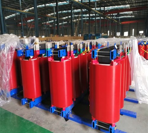
| Dry-type (cast resin, SCB13 / SCB14) | Indoor rooms, basements, occupied buildings, rooftops | Sealed enclosures derate the unit — ask for the enclosure derating factor |
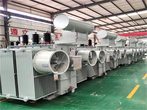
| Oil-immersed (S13 / S20) | Outdoor pads, yards, utility-owned gear | Containment and fire separation; oil sampling becomes a maintenance item |
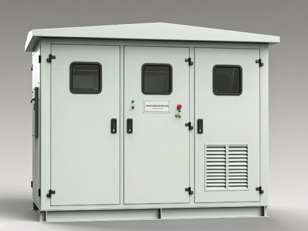
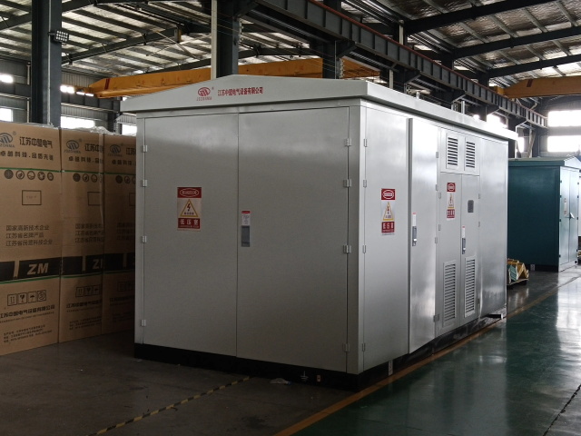
| Packaged / prefabricated substation (YBW series) | Fast-track DC fast-charging sites, greenfield pads | Footprint, delivery access, and utility acceptance of a factory-assembled unit |
Cooling method drives most of the real-world difference between these. Our breakdown of transformer cooling classes (ONAN, ONAF, AN, AF) explains how each designation translates into the performance you actually get on a hot day, and why adding a fan stage to a cast resin unit can buy you real capacity rather than just a datasheet footnote.
For a greenfield fast-charging site on a tight schedule, a packaged substation built for DC fast charging is usually the fastest route from permit to energization: transformer, MV and LV switchgear, metering, and protection arrive factory-assembled and tested as one unit, which compresses on-site work and simplifies commissioning. We run this delivery model on utility-scale programs too — see our 11 kV / 33 kV compact substation program for an overseas utility EPC.
—
5. Built for Charger Duty
A charging station is not a normal building load, and a general-purpose distribution transformer will show it. EV charging produces intermittent, sharply peaked demand with significant harmonic content as dispensers switch on and off. Units built for this duty are engineered around exactly that:
- Harmonic mitigation designed in, so charger switching does not distort the waveform feeding the rest of the site. A Dyn11 vector group lets triplen harmonics circulate and be trapped in the delta winding instead of propagating back to the primary; an electrostatic shield between windings attenuates common-mode noise. K-factor ratings are the usual specification language here.
- High surge withstand, absorbing the repeated start-stop voltage swings without insulation stress or nuisance tripping.
- Protection for downstream equipment — the dispensers themselves and the vehicle batteries connected to them.
- Fully sealed enclosures rated against water, dust, and corrosion, so the unit is equally at home on an exposed outdoor pad or in a damp underground room. Specify IP54 / NEMA 3R as the outdoor baseline and NEMA 4X for coastal or chemically aggressive sites; ISO 12944 C4/C5 for the coating system.
Harmonic performance is the spec most often missed at bid stage. The engineering logic is identical to the one we applied on a K-factor dry-type transformer project for a hyperscale data center — different load profile, same problem, same fix.
—
6. Efficiency and Lifetime Cost
Quality units in both ratings are built on energy-efficient platforms: S13 / S20 for oil-immersed and SCB14 for cast resin dry-type. Over a decade of continuous operation on a commercial tariff, the loss difference between platforms is one of the larger cost items you actually control.
Two rules of thumb worth holding on to:
- No-load loss is charged 24/7. A charging site stays energized whether or not anyone is plugged in, so no-load loss is a fixed cost you pay every hour of the year. At confirm your tariff per kWh, each 1 kW of no-load loss is on the order of confirm per year.
- Load loss is charged by the square of the load. A site averaging 60–70% load pays roughly 36–49% of the nameplate load loss — which is why a high-efficiency core pays back faster on a busy plaza than on a quiet community lot.
Before you compare quotes, know how to read the numbers: our guide to reading a transformer nameplate and technical parameters covers the loss columns, impedance, vector group, and temperature rise class. Note that DOE 10 CFR 430 coverage depends on rating and type — confirm whether your specific rating, voltage class, and 60 Hz design fall inside the covered scope, because outside it, efficiency has to be locked down contractually rather than by regulation.
Most suppliers in this range will also deliver the complete distribution package — HV and LV switchgear, metering, and monitoring — as one coordinated scope, which avoids the finger-pointing that happens when five vendors each supply a piece of the same single-line diagram.
—
7. 800 vs 1000: How to Decide
- Choose 800 kVA for small communities, scattered dispensers, residential garages, and sites with modest daily throughput. You get a better return on capital and avoid idle capacity. Equivalently, on North American schedules, 750 kVA.
- Choose 1000 kVA for commercial-scale stations, high-traffic public sites, and anything expected to run near full load for extended hours. The extra headroom absorbs future dispenser additions without a second distribution retrofit.
A simple way to frame it: 800 kVA optimizes for today’s load; 1000 kVA optimizes for the load you will have in three years. Where trenching, utility coordination, and switchgear replacement are the expensive parts — which is almost everywhere — the second option is usually cheaper over the life of the asset. Sizing methodology, standards, and testing are covered in the technical resource library.
—
8. Specification Checklist
- Charger list: quantity, per-dispenser rating, connector type, and whether power sharing or load management is fitted.
- Calculated kVA using Sₙ = ΣP × Kₜ × Kₛ, with both factors written down and justified.
- Utility primary voltage and frequency — and if the project is 60 Hz, say so at RFQ stage.
- Secondary voltage: 400 V, 480Y/277 V, or 600Y/347 V.
- Rating as approved by the utility: 800 kVA (IEC) or the 750 / 1000 kVA ANSI equivalent.
- Build type and cooling class, plus the enclosure derating factor if it is a sealed outdoor unit.
- Efficiency platform (S13, S20, SCB14) and the target standard: GB 20052, EU Ecodesign, or DOE.
- Vector group (Dyn11 typical) and K-factor requirement for harmonic duty.
- Enclosure rating: IP54 / NEMA 3R baseline, NEMA 4X for coastal or industrial atmospheres.
- Noise limit at the property line in dB(A) — confirm the measured sound level for your unit.
- Short-circuit impedance (%Z) coordinated with your switchgear’s interrupting rating.
- Scope boundary: transformer only, or switchgear, metering, and monitoring as a complete package.
—
9. FAQ: 800 kVA and 1000 kVA Charging Transformers
What size transformer does an EV charging station need?
Work from simultaneous demand, not the sum of nameplate ratings. Most small to mid-size sites land on 800 kVA; highway plazas, bus depots, and other high-throughput commercial sites start at 1000 kVA. Run Sₙ = Σ charger kW × simultaneity factor × margin factor before you commit.
800 kVA or 1000 kVA — which should I choose?
Use 800 kVA for small communities, scattered chargers, and low daily throughput. Step up to 1000 kVA for commercial-scale stations, high-traffic public sites, or anything running near full load around the clock, because the headroom lets you add dispensers later without touching the distribution equipment.
How many DC fast chargers will a 1000 kVA transformer support?
Roughly 8 × 120 kW comfortably, or 10 × 120 kW at the limit, assuming a 0.7 simultaneity factor and a 1.2 margin. With load management you can push to 12 × 120 kW. Share your dispenser schedule with your supplier and ask them to run the actual load study.
Is 800 kVA available for a US project?
Not as a standard size. 800 kVA is on the IEC schedule; the ANSI/IEEE three-phase schedule steps 750 → 1000 kVA. For North American projects, order the 750 kVA equivalent or move to 1000 kVA, and confirm the approved size list with your utility and AHJ before design freeze.
Why does EV charging need a transformer with harmonic mitigation?
Dispensers draw power in sharp, intermittent bursts and inject harmonics back into the system. A transformer not designed for it lets those harmonics distort site voltage, which can throttle dispenser output, trip protection, and stress both the charging equipment and vehicle batteries. Specify a Dyn11 vector group and a K-factor rating appropriate to your dispenser mix.
Dry-type or oil-immersed for a charging station?
Dry-type cast resin is the usual choice indoors and in occupied or below-grade spaces, thanks to fire performance and low noise. Oil-immersed units are typically more economical outdoors at these ratings. Both are offered at 800 and 1000 kVA, so location and local code usually decide it.
When does a packaged substation make sense?
For DC fast-charging sites on tight schedules. The transformer, switchgear, and protection arrive factory-assembled and tested, which compresses on-site work and simplifies commissioning and utility acceptance.
Can I expand later if I start with 800 kVA?
Only up to the margin you leave yourself. If adding dispensers is plausible within a few years, 1000 kVA from day one is almost always cheaper than replacing an 800 kVA unit and re-coordinating with the utility later.
Do these units run at 60 Hz?
They can, but frequency is a core design input set when the core is cut and cannot be corrected afterwards. State 60 Hz at the RFQ stage, along with the primary voltage and required BIL.
What efficiency standards should I specify?
S13 or S20 for oil-immersed and SCB14 for cast resin dry-type, against GB 20052, EU Ecodesign, or DOE 10 CFR 430 depending on your market. Confirm no-load and load loss figures on the nameplate — those two numbers drive most of the lifetime energy cost at a site that stays energized continuously.