A 500 kVA transformer is the sweet-spot rating for small and mid-size DC fast charging sites. It typically carries 6–8 × 60 kW DC chargers or 4–5 × 120 kW dual-gun units, covers a site load band of roughly 180–360 kW, and — unlike 400 kVA or 630 kVA — it is a stock rating on both IEC schedules and North American pad-mounted schedules, so you are not paying for a custom build. This page covers the sizing math, the two model families (SCB13/14/18 dry-type and S20/S22/SH15 oil-immersed), and the specification mistakes that cause overload trips a year after handover. For the site-level view — enclosures, MV switchgear, metering, and utility acceptance — start with our guide to EV charging station transformers and packaged substations.
Standards baseline: IEC 60076 series · IEC 62271-202 (prefabricated substations) · GB 20052-2020 Grade 1 (China MEPS) · ANSI/IEEE C57.12 and DOE 10 CFR 430 for North American projects · ISO 9001 / 14001 / 45001. UL listing: available on request.
1. Where a 500 kVA Charging Transformer Fits
1.1 The load band it was built for
A 500 kVA unit is the mainstream rating for light commercial and residential-adjacent charging:
| Site type | Typical build | Why 500 kVA lands here |
|---|---|---|
| Residential community basement garage | 6 × 60 kW DC + 8–12 × 7 kW AC | Fits the standard residential MV feed; dry-type keeps the fire marshal happy |
| Retail / mall / supermarket parking | 4 × 120 kW dual-gun | Matches a 2–3 hour dwell time and an evening peak |
| Small industrial park | 8 × 60 kW DC for staff and fleet vans | Daytime load is spread across shifts |
| Township / county public charging | 4–6 × 60 kW DC | Low duty cycle, long light-load hours |
| Scenic area / tourism parking | 6 × 60 kW DC, seasonal peaks | Seasonal overload is short and predictable |
In round numbers, that is a 180–360 kW DC fast-charging load band. It is also the default capacity when an older residential compound is being upgraded: the existing MV cable and switchgear usually have just enough headroom for 500 kVA, but not for 630 kVA.
1.2 Why 500 kVA and not 315 or 630 kVA
- 315 kVA is a dead end. It supports roughly 4–5 × 60 kW chargers (or 2 × 120 kW units) with proper margin. The moment you add a third fast charger or a second dual-gun cabinet, you are swapping the transformer — and re-doing the utility connection.
- 630 kVA is money spent early. Expect a higher purchase price, higher no-load losses, a larger enclosure or pad, and higher prospective fault current that forces heavier switchgear and cable. It only pays back if you will genuinely add chargers within 12–24 months.
- 500 kVA threads the needle. Enough margin to absorb a charger addition, small enough to keep the pad, the switchgear, and the utility bill reasonable — and it is one of the few ratings that is standard on both IEC and North American schedules.
1.3 Sites that should [Confirm] not pick 500 kVA
Be honest about these before you order:
- Fleet depots and bus terminals with a fixed overnight window. Every vehicle plugs in within the same two hours, so the simultaneity factor is 0.9–1.0, not 0.6–0.8. A 6 × 120 kW depot needs roughly 820 kVA, not 500.
- Highway corridor hubs with 8 or more 120 kW+ dispensers.
- Sites where charging shares the transformer with a large existing load (cold storage, workshop machinery, a data room). Size the transformer for the sum, not for the chargers alone.
2. Capacity Matching: How Many Chargers Will 500 kVA Really Carry
Use the same sizing equation we use across our charging projects:
Rated capacity Sₙ (kVA) ≥ Σ charger nameplate (kW) × simultaneity factor Kₜ × margin factor Kₛ
| Factor | Value | How to pick it |
|---|---|---|
| Simultaneity factor Kₜ | 0.6–0.8 (public sites) | 0.8–1.0 for 1–4 chargers; 0.6–0.8 for 5–10; 0.5–0.7 above 10. Use 0.9–1.0 for fleet sites with a fixed charging window. |
| Margin factor Kₛ | 1.2–1.3 | Covers peak loading, cable and charger conversion losses, site auxiliary load, and the headroom you will want when you add chargers. |
About the ÷ power factor term. Some Chinese specification sheets write the same equation as Sₙ = P × Kₜ × Kₛ ÷ cos φ (0.9–0.95). Do not stack both versions — dividing by 0.9 on top of a 1.2 margin inflates the answer by about 11% and quietly pushes you a full rating step up. Modern charger power modules use active front ends with a displacement power factor around 0.98–0.99, so the correction is normally already inside Kₛ. Apply it only once, and only if your charger vendor quotes input kVA rather than DC output kW.
2.1 Worked configurations
| Configuration | Total DC nameplate | Kₜ assumed | Required kVA (×1.2) | Verdict for 500 kVA |
|---|---|---|---|---|
| 6 × 60 kW DC fast | 360 kW | 0.7 | 302 | Comfortable — about 40% spare |
| 8 × 60 kW DC fast | 480 kW | 0.7 | 403 | Good fit |
| 8 × 60 kW, unmanaged evening peak | 480 kW | 0.85 | 490 | Borderline — add load management |
| 10 × 60 kW DC fast | 600 kW | 0.6 | 432 | Fits with managed charging |
| 4 × 120 kW dual-gun | 480 kW | 0.7 | 403 | Good fit |
| 5 × 120 kW dual-gun | 600 kW | 0.7 | 504 | Over — needs load sharing or 630 kVA |
| 4 × 120 kW + 10 × 7 kW Level 2 | 550 kW | 0.65 | 429 | Good fit |
| Fleet depot, 6 × 120 kW overnight | 720 kW | 0.95 | 821 | Not a 500 kVA site |
Two things the table hides:
A “120 kW dual-gun” charger rarely delivers 120 kW to both guns at once. The rating is shared across the two connectors by a power-splitting controller. Size against the vendor’s power-sharing curve, not the badge number — this is why “5 × 120 kW” sometimes fits on 500 kVA and sometimes does not.
Peak and off-peak matter more than the daily average. Charging load is evening-peaked at commuter and retail sites, and flat-and-high at depots. A 500 kVA unit built for charging duty typically carries a 15–20% short-term overload capability, which is what gets you through the 18:00–21:00 spike without a trip. See §6.4 for why that number needs a definition, not just a percentage.
For the full step-by-step method — including the environmental and installation parameters that sit alongside capacity — see EV Charger Transformers: Sizing, Selection, and Installation. This page is the capacity-specific layer on top of it.
3. Technical Specifications
Typical values for a 500 kVA charging-duty transformer. Anything marked [Confirm] confirm must come off the type-test report or the utility’s interconnection requirements, not off a brochure.
| Parameter | Typical value | What to specify |
|---|---|---|
| Rated capacity | 500 kVA | ONAN (oil) or AN (dry-type) base rating; AF/ONAF ratings are forced-cooled and not continuous |
| Primary voltage | 10 kV or 20 kV (China); 12.47 / 13.8 / 34.5 kV (North America) | Match the serving utility exactly — do not assume |
| Secondary voltage | 400/230 V (IEC); 480Y/277 V (US); 600Y/347 V (Canada) | A Chinese 380 V spec becomes 480Y/277 V in North America; confirm the charger modules’ input window before ordering |
| Frequency | 50 Hz standard build | 60 Hz must be stated at RFQ. It cannot be changed after the core is cut |
| Vector group | Dyn11 (Δ/Yn-11) | Traps third harmonics and gives a four-wire secondary. IEC Dyn11 is written Dyn1 on ANSI/IEEE drawings — confirm the notation with your utility |
| Short-circuit impedance | 4%–5% at ~13.8 kV class; 6%–7% at 34.5 kV class (4%–6% is the band usually quoted for charging-site distribution transformers) | Too low raises fault current and forces heavier switchgear; too high causes voltage sag every time a charger ramps |
| Insulation system | Class F or Class H (dry-type); mineral oil IEC 60296, synthetic ester IEC 61099, or natural ester IEC 62770 (oil) | Class H dry-type where fire code drives the spec; ester fluid where a flammable liquid is restricted |
| Cooling | AN / AF (dry-type); ONAN (oil) | Forced cooling adds capacity and noise — budget for both |
| Off-circuit taps | ±2 × 2.5% on HV | OLTC only if the utility feed is genuinely unstable |
| Sound level | [Confirm] confirm — declared sound power level per IEC 60076-10 | Ask for the sound power level (L_WA), not a sound pressure figure measured at an unspecified distance |
| No-load / load loss | [Confirm] confirm per type test | Needed for the lifetime cost calculation in §4.3 |
| Enclosure | IP23–IP54 (dry-type); pad-mounted NEMA 3R; IEC 62271-202 for packaged substations | IP54 seriously restricts cooling — it must be paired with forced ventilation or derating, and forced ventilation raises noise |
| Short-term overload | 15–20% | Define pre-load, duration, and ambient per IEC 60076-7 (oil) or IEEE C57.91 — see §6.4 |
Verify each of these against the nameplate on delivery; our walkthrough of how to read a transformer nameplate and technical parameters shows which fields buyers most often mis-read.
4. Dry-Type vs Oil-Immersed: Picking the Model Family
Both families are available at 500 kVA. The choice is driven by where the unit sits, not by electrical performance.
4.1 The decision table
| Decision driver | Dry-type (cast resin) | Oil-immersed |
|---|---|---|
| Installation | Indoor, basement garage, enclosed retail, rooftop plant room | Outdoor, open lot, roadside, fenced compound |
| Fire and life safety | Flame-retardant, self-extinguishing, no flammable liquid — usually the only option that passes enclosed-space fire review | Requires an oil containment pit, fire separation, and in the US secondary containment per EPA SPCC rules |
| Maintenance | Effectively none: annual inspection, clean cooling paths, check terminations | Adds oil level and dielectric checks plus periodic dissolved-gas analysis |
| Overload tolerance | Good, but thermally limited in still air | Better — oil mass and ONAF give real thermal inertia |
| Noise | Low at AN rating; fans are the hidden noise source | Low, but siting distance is your friend |
| Upfront cost | Higher at the same rating | Lower |
| Life expectancy | 20–25 years in a clean, dry room | 25–30 years outdoors |
4.2 Model codes, decoded
| Model code | What it actually means | Where it belongs |
|---|---|---|
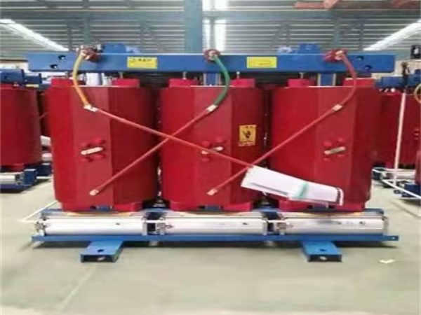
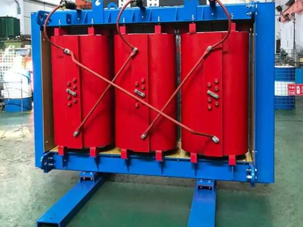
| SCB13 / SCB14 / SCB18 | Cast resin dry-type, epoxy encapsulated. The number is the GB loss-series code — higher means lower loss | Indoor, basement garage, enclosed commercial |
| SCBH15 | Dry-type with an amorphous alloy core (干式非晶合金) | Indoor sites with many light-load hours |
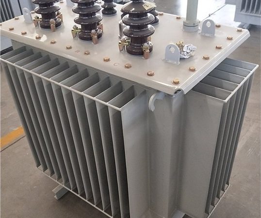
| S20 / S22 | Oil-immersed, silicon-steel core; S22 is the lower-loss tier | Outdoor open sites at moderate-to-high load factor |
| SH15 | Oil-immersed amorphous alloy core (油浸非晶合金) | Outdoor sites that sit light most of the day — township, rural, scenic |
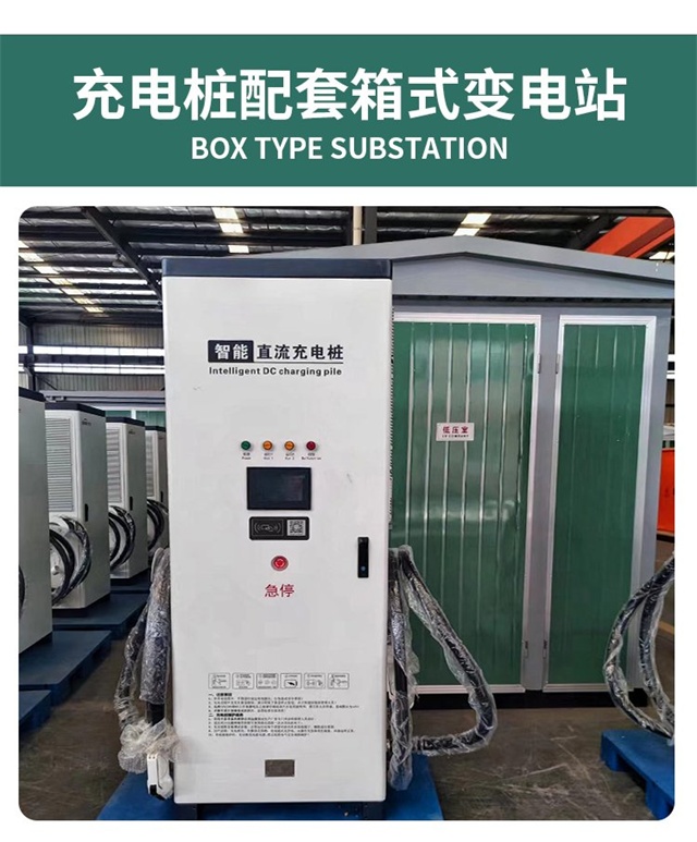
| YBW / compact substation | Prefabricated substation: transformer + MV + LV + metering in one enclosure | Retrofits and capacity upgrades |
The GB model numbers map to China’s national efficiency standard, GB 20052-2020. Overseas buyers will not recognise that number, so quote it alongside IEC 60076 loss figures and — for EU and US projects — the Ecodesign PEI or DOE values. [Confirm] Confirm the current grade mapping for each model code before you put it in a contract.
4.3 The amorphous trade-off nobody puts in the brochure
Amorphous cores (SH15, SCBH15) cut no-load loss substantially — typically 40–50% versus an equivalent silicon-steel unit — but they carry a price premium and are usually a few dB noisier. No-load loss is what you pay for every hour the transformer is energised, so:
- Community basement garage or township site: energised 24/7 but lightly loaded most of the day → amorphous pays back.
- Mall or highway-adjacent site running a high load factor: load loss dominates the bill, and the amorphous premium largely goes to waste → a low-loss silicon-steel design (S22 / SCB14) is usually the better value.
Run the number before you buy: annual kWh ≈ no-load loss (kW) × 8,760 + load loss (kW) × load factor² × 8,760, then multiply by your tariff. Insert the type-test loss figures and your own load factor — a generic “saves energy” claim is not a business case.
For a fuller side-by-side, read oil-immersed vs dry-type: how to choose. Model families and current ratings: cast resin dry-type transformers and oil-immersed distribution transformers.
5. Three Typical 500 kVA Configurations
A. Community basement garage. SCB14 500 kVA cast resin dry-type, Class H, AN cooling, IP23 enclosure, Dyn11. Serves 6 × 60 kW DC fast chargers plus 8 × 7 kW Level 2 AC points. No oil, no containment pit, no fire-rated transformer room — the reason dry-type wins underground.
B. Mall open parking. S22 (or SH15 where the site sits light most of the day) 500 kVA oil-immersed, ONAN, pad-mounted or fenced compound, IP54 / NEMA 3R. Serves 4 × 120 kW dual-gun units. Lower capital cost, real overload headroom, and siting distance solves the noise question.
C. Older site capacity upgrade. YBW-series prefabricated compact substation with a 500 kVA unit, MV protection, LV distribution, and revenue metering in one enclosure. Skips the building work almost entirely — the fastest route when the existing room has no space and the outage window is short.
These three reflect what actually ships. For reference installations, see our delivered projects.
6. Six Specification Mistakes to Avoid
6.1 Sizing to 100% of the rating. Never configure a site that leaves zero headroom. If the calculation lands at 480 kVA against a 500 kVA unit, you have no room for the chargers you will add next year — and adding them means a transformer swap, a new utility application, and a site outage.
6.2 Treating “all-copper windings” as the only quality signal. Copper is the right default for charging duty: better conductivity, lower loss, longer life under thermal cycling. But the usual failure mode on aluminium-wound units is the terminations, not the windings — thermal cycling plus galvanic corrosion at the lugs. If a supplier quotes aluminium, do not reject it reflexively; ask for bi-metallic terminations, published torque values, and a thermal cycling test report instead.
6.3 Skipping harmonic mitigation and power-factor correction. Charger rectifiers are non-linear loads. Specify harmonic mitigation and reactive compensation with the transformer, not after the first power-quality complaint, and hold the site to IEEE 519 (or IEC 61000-2-4 outside North America) limits at the point of common coupling.
6.4 Accepting “15–20% overload” without a definition. An overload figure is meaningless on its own. Per IEC 60076-7 (oil) and IEEE C57.91 (general loading guidance), short-term emergency loading depends on the pre-load, the ambient temperature, the duration, and the cooling stage. It is an emergency capability for a peak spike, not a design margin you are allowed to size against.
6.5 Ignoring the retrofit path. If the existing electrical room is full, a prefabricated compact substation usually beats new civil work on both schedule and cost — no new building, minimal outage, and the assembly is factory-tested before it arrives.
6.6 Leaving 60 Hz and 480Y/277 V to the end. Chinese standard builds are 50 Hz with a 400/230 V secondary. North American projects need 60 Hz, a 12.47 / 13.8 / 34.5 kV primary, and a 480Y/277 V (600Y/347 V in Canada) secondary, built and tested to ANSI/IEEE including BIL levels. Frequency and voltage are design inputs, not accessories.
7. Standards and Compliance
| Scope | Standard | What it governs |
|---|---|---|
| Power transformers, general | IEC 60076-1 / -2 / -3 | Ratings, temperature rise, dielectric requirements |
| Short-circuit withstand | IEC 60076-5 | Ability to survive through-faults — routine on charging duty because of frequent switching |
| Thermal loading guidance | IEC 60076-7 (oil), IEEE C57.91 | How overload capability must be defined |
| Dry-type transformers | IEC 60076-11 | Fire behaviour (F1), environmental (E2), climatic (C2) classes |
| Sound | IEC 60076-10 / -10-1 | Declared sound power level — the number to quote in noise-sensitive specs |
| Prefabricated substations | IEC 62271-202 | The international reference for packaged/compact substations |
| North American product standards | IEEE C57.12.00, C57.12.90; C57.12.20 (pad-mounted) | Construction and testing for ANSI-built units |
| US installation | NFPA 70 (NEC) Article 450 (transformers), Article 625 (EV charging systems) | Clearances, overcurrent protection, disconnecting means |
| US efficiency | DOE 10 CFR 430 | Applies to covered distribution transformers — [Confirm] confirm current scope and the applicable efficiency table for this rating and insulation type |
| EU efficiency | EU Ecodesign Regulation 2019/1783 (PEI) | [Confirm] Confirm applicability, tier, and any exemption for your rating |
| China efficiency | GB 20052-2020 Grade 1 | China’s minimum energy performance standard; quote alongside IEC, EU, and DOE parameters |
| Harmonic limits | IEEE 519 (US) / IEC 61000-2-4 | Voltage and current distortion limits at the PCC |
| Quality systems | ISO 9001 / 14001 / 45001 | Manufacturing and process control |
8. FAQ: 500 kVA Charging Transformers
How many DC fast chargers can I run on 500 kVA?
As a working rule, 6–8 × 60 kW units or 4–5 × 120 kW dual-gun units. Run it through Sₙ = ΣP × Kₜ × Kₛ before committing: 8 × 60 kW at a 0.7 simultaneity factor needs 403 kVA, but at 0.85 (an unmanaged evening peak) it needs 490 kVA — and 5 × 120 kW at 0.7 lands at 504 kVA, just over. Charger count alone is not the answer; the simultaneity factor is.
Should I just go to 630 kVA for safety?
Only if you will add chargers within 12–24 months. Otherwise you pay more up front, carry higher no-load losses for the life of the unit, need a larger pad, and push fault current high enough to affect protective device coordination. Oversizing by one standard rating step is normal; going two steps rarely pays off.
Why 500 kVA specifically, and not 400 or 630?
500 kVA is one of the few ratings that is standard on both IEC schedules and North American three-phase pad-mounted stock (commonly 300 / 500 / 750 kVA). That means shorter lead times and no custom-build premium, while still leaving margin above 400 kVA for future chargers.
Can I use a Chinese 10 kV / 380 V unit on a US site?
Not as-is. North American primaries are typically 12.47 kV, 13.8 kV, or 34.5 kV; secondaries are 480Y/277 V (600Y/347 V in Canada); and the unit must be built and tested to ANSI/IEEE rather than IEC — including BIL levels and vector group notation, where IEC Dyn11 is written Dyn1. Plan a purpose-built ANSI unit instead of adapting an IEC design.
Can a 50 Hz transformer run on a 60 Hz grid?
Ask for a 60 Hz design at the RFQ stage. Frequency is a core design input — it is set when the core is cut and cannot be corrected afterwards. The same applies in reverse for 50 Hz markets.
Dry-type or oil-immersed for an underground garage?
Dry-type, almost always. Enclosed and occupied spaces below grade leave you no good answer for fire review on a flammable liquid, and cast resin units are flame-retardant and self-extinguishing. Oil units also need a containment pit, which a basement rarely has space for.
What does “15–20% short-term overload” actually mean, and can I rely on it?
It is an emergency capability, not a design margin. Per IEC 60076-7 and IEEE C57.91, what you can draw depends on the pre-load, ambient temperature, duration, and cooling stage. Ask the supplier to state all four, and size the base rating so you never need the overload to serve normal demand.
What do I need to send you to get a quote for a 500 kVA charging transformer?
Six things: (1) number, rating, and connector type of chargers, plus whether load sharing is fitted; (2) utility primary voltage and frequency, and the required secondary voltage; (3) installation location — indoor/basement or outdoor/open; (4) target efficiency standard (GB 20052, EU Ecodesign, or DOE); (5) enclosure or pad-mount requirement and any noise limit at the property line; (6) site photos or a single-line diagram. With those, we can return a sized proposal and a budgetary range, typically within one business day.