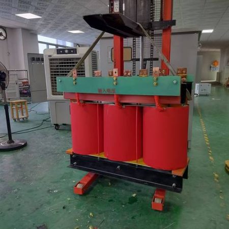
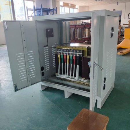
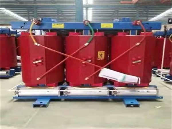
A single-phase cylindrical-winding transformer is a small dry-type unit whose coils are wound as concentric layers directly around the core limb. To price one you need four rating numbers, four performance numbers and four construction choices — and the voltage pair you give us has to be the one your grid actually delivers. This page defines every parameter in plain English, shows how each one is measured, and works a 10 kVA example from nameplate through to short-circuit current, efficiency and voltage drop.
Standards this page works to: IEC 60076-1 (general), IEC 60076-2 (temperature rise), IEC 60076-3 (insulation levels and dielectric tests), IEC 60076-5 (short-circuit withstand), IEC 60076-11 (dry-type), IEC 60085 (thermal classes); IEEE C57.12.00 / C57.12.01 / C57.12.90 and NEMA ST 1 for North America; UL 506 and UL 5085 for the US market. Loss figures, temperature-rise limits, UL coverage and DOE scope on any specific unit must be read off the test report — every unverified value on this page is marked for confirmation.
1. What “Single-Phase Cylindrical-Winding” Actually Means
“Cylindrical” describes how the coil is wound, not a separate product category. The conductor is wound layer by layer over insulating paper or film directly around the core limb, so the finished coil is a cylinder — also called a barrel or layer winding. It is the natural construction for small single-phase units and for the higher-voltage winding of larger ones.
The alternatives matter when you read a quote:
| Winding construction | How it is built | Where you meet it | Trade-off |
| Cylindrical / layer (barrel) | Round or flat wire wound in concentric layers on the limb | Small single-phase units, HV windings up to about 36 kV | Simple, good impulse voltage distribution, easy to insulate layer-to-layer; modest short-circuit strength compared with a disc winding |
| Foil | Continuous copper or aluminium foil, one turn per layer | Low-voltage, high-current windings | Excellent space factor and short-circuit strength; essentially a low-voltage construction |
| Disc / helical | Flat wire wound as stacked discs separated by spacers | Medium and large power transformers | Best short-circuit withstand and cooling; overkill below roughly 100 kVA |
Two more distinctions buyers routinely miss:
- Dry-type, not liquid-filled. A cylindrical-winding single-phase unit as described here is an air-cooled dry-type transformer for indoor panels, machines and control cabinets. It is not the oil-filled single-phase can you see on a utility pole — that is a 12.47 kV or 34.5 kV class distribution transformer with a completely different standard set ([Confirm: confirm which you actually need before you send the RFQ]).
- Specialty, not catalogue distribution. In North America this class of product sits under NEMA ST 1 (specialty transformers) and is listed to UL 506, not to the general-purpose dry-type standard UL 1561. If your panel shop needs a UL mark, say which one you need at RFQ stage.
Single-phase cylindrical-winding units live in the special-transformers family next to furnace, rectifier and marine units; the general product catalogue shows where they sit against the standard three-phase ranges.
2. Nameplate (Rated) Parameters: The Five Numbers That Define the Unit
These are the conditions the designer sized the iron and copper for. Everything else on the page is a consequence of them.
| Parameter | What it really means | What to check before you accept a quote |
| Rated power S | Apparent power in VA or kVA at the secondary terminals under rated conditions | It is VA, not watts. A 10 kVA unit delivers 10 kW only at unity power factor and 8 kW at 0.8 pf. Size the core on VA and the load on watts |
| Rated primary voltage U1N | The voltage the primary winding is designed to receive | Give the system voltage, including any taps (±2 × 2.5%, ±5%, and whether they are off-circuit or on-load) |
| Rated secondary voltage U2N | Voltage at the secondary terminals with rated primary applied and no load | This is an open-circuit figure. The voltage you measure under load is lower by the regulation — see Section 5 |
| Rated currents I1N, I2N | Currents at rated power and rated voltages | Derived, not chosen. They set conductor size, terminal size and protective device ratings |
| Rated frequency | 50 Hz or 60 Hz | Must be stated at RFQ. It is not a preference, it is a design input — see FAQ 3 |
The current formula for a single-phase unit is the source formula, and it is correct:
The single-phase and three-phase forms are not interchangeable, and this is one of the most common arithmetical errors in a specification: dividing a three-phase kVA rating by a single-phase voltage gives a current that is √3 too large.
If you want the full walk-through of plate fields, tap markings and vector-group symbols, the nameplate and technical-parameter guide covers it separately; this page stays on the parameters themselves.
3. Fix the Voltage Pair First: Chinese Ratings vs North American Service
The example in the source data is a 220 V to 110 V unit at 50 Hz. That pair does not exist as a service voltage in the United States. Before you send anything to a factory, convert it.
| Market | Primary | Secondary | I1N at 10 kVA | I2N at 10 kVA |
| China / much of Asia, 50 Hz | 220 V | 110 V | 45.5 A | 90.9 A |
| US split-phase, 60 Hz | 240 V | 120 V | 41.7 A | 83.3 A |
| US industrial control power, 60 Hz | 480 V | 120 V | 20.8 A | 83.3 A |
| US lighting circuits off 277 V, 60 Hz | 277 V | 120 V | 36.1 A | 83.3 A |
| Canada, 60 Hz | 600 V | 120 V | 16.7 A | 83.3 A |
Three traps in that table:
- 110 V is not a US utilisation voltage. It is 120 V, and the corresponding primary on a residential or light-commercial board is 240 V, not 220 V.
- On a 480Y/277 V board you take 277 V for a single-phase circuit, not 480 V. Line-to-neutral is 277 V; line-to-line is 480 V. Specifying a 480 V primary when you are feeding it from line-to-neutral gives you a unit that runs at half flux and half its rated output.
- 480 V to 120 V is the workhorse. In North American machine and control panels this is the standard control power transformer: 480 V primary, 120 V secondary, a fuse or breaker on each side, and a grounded secondary per NEC Article 450 and the machine standard your panel is built to [Confirm: confirm against the applicable machine standard and AHJ].
If your existing equipment is 400 V or 380 V and you are moving it to a North American site, that is a voltage-conversion problem, not a re-labelling exercise — the 480 V to 380 V conversion page covers what changes and what does not.
4. Performance Parameters: Losses, Impedance, Regulation
These five numbers decide what the transformer costs you to run and what it does to your protection.
| Parameter | How it is measured | What it drives | The pitfall |
| No-load loss P0 (iron loss) | Secondary open, rated voltage at rated frequency on the primary | Energy bill every hour the unit is energised, whether or not it carries load | It is billed 8,760 h/year. It usually dominates on lightly loaded circuits |
| Load loss Pk (copper loss, short-circuit loss) | Secondary short-circuited, rated current circulated in the primary | Heat, and energy that scales with the square of the load | Quotes are meaningless unless the reference temperature is stated — see below |
| No-load current I0 | Secondary open, current drawn by the primary, given as a percentage of I1N | Magnetising demand, upstream sizing | It is mostly reactive. It is not the same number as no-load loss — see FAQ 6 |
| Impedance voltage Uk% | Voltage applied to the primary, secondary shorted, that circulates rated current | Prospective short-circuit current, and whether units can run in parallel | Low impedance gives better regulation and a much higher fault current, which your downstream devices must be rated for |
| Voltage regulation | Change from no-load to full-load secondary voltage | Whether equipment at the end of the circuit stays in band | It depends on power factor. A single number without a stated power factor is unusable |
Normalise the reference temperature before you compare quotes
Load loss is a resistance loss, so it scales with winding temperature. Chinese practice under GB/T 10228 normally reports it at the insulation-class reference temperature (for a Class F unit that is typically 120 °C); IEC and North American practice often use 75 °C. For copper windings:
So a value reported at 120 °C is about 14.6% higher than the same winding reported at 75 °C — purely a bookkeeping difference. Two quotes that look 15% apart may be identical. Always ask for the reference temperature alongside the number [Confirm: confirm the reference temperature used in the quote you are comparing].
The efficiency formula most spec sheets get wrong
The usual shorthand, output divided by output plus losses, is only true at full load and unity power factor. The usable form is:
Load loss enters as β², not β, and the real output power depends on the load power factor. Both omissions flatter the transformer at part load.
Regulation needs the R/X split, not just the impedance
Impedance percentage alone does not give you voltage drop. You need the resistive and reactive parts:
At unity power factor the reactive term vanishes; at 0.8 lagging it dominates; at leading power factor the two terms partly cancel and the secondary voltage can even rise. Section 5 derives both parts from the source data.
5. The 10 kVA Example, Worked End to End
Take the source example: 10 kVA, 220 V primary, 110 V secondary, P0 ≤ 40 W, Pk ≤ 250 W, I0 ≤ 2.5%, Uk = 4%, AN cooling, Class B insulation. Here is everything that follows from it.
Step 1 — Rated currents. I1N = 10,000 / 220 = 45.45 A. I2N = 10,000 / 110 = 90.91 A.
Step 2 — Prospective short-circuit current. With 4% impedance, the current that flows with the secondary bolted and rated primary applied is the rated current divided by 0.04:
That is the symmetrical RMS figure. The first peak is materially higher because of the DC offset, and protective devices are rated on the asymmetrical value, so ask the supplier for the X/R ratio and check your downstream devices against it [Confirm: obtain X/R ratio and confirm SCCR of downstream equipment per NEC 110.10 / UL 508A].
Step 3 — Split the impedance into R and X. Load loss at rated current gives the resistance directly:
Step 4 — Voltage regulation at full load.
| Load power factor | ΔU% = R%·cos φ + X%·sin φ | Secondary voltage at full load |
| 1.0 (resistive) | 2.50 × 1 + 3.12 × 0 = 2.5% | 107.3 V |
| 0.8 lagging (motors, most real loads) | 2.50 × 0.8 + 3.12 × 0.6 = 3.9% | 105.7 V |
| 0.8 leading | 2.50 × 0.8 − 3.12 × 0.6 ≈ 0.1% | 109.9 V |
So a nameplate that says 110 V is telling you the open-circuit voltage. At 0.8 pf lagging you measure roughly 106 V, and if your load will not tolerate that you specify a lower impedance or an off-circuit tap to compensate.
Step 5 — Efficiency at three operating points.
| Operating point | Output | Losses | Efficiency |
| Full load, pf 1.0 | 10,000 W | 40 + 250 = 290 W | 97.2% |
| Full load, pf 0.8 | 8,000 W | 290 W | 96.5% |
| Half load, pf 1.0 | 5,000 W | 40 + 250 × 0.25 = 102.5 W | 98.0% |
Note that efficiency peaks at part load, which is exactly where most of these units spend their life, and that it drops as the load power factor drops even though the transformer itself is unchanged.
Step 6 — What it costs to run. No-load loss runs 8,760 h/year regardless of load; load loss runs on the square of the load factor.
On a small unit the purchase price usually dwarfs that — which is the honest way to look at it. If the unit is one of hundreds on a site, or runs at low load factor for 20 years, no-load loss becomes the number worth paying for. [Confirm: substitute the losses from the actual test report and your own tariff and loading hours.]
Step 7 — No-load current is not no-load loss. I0 = 2.5% × 45.45 = 1.14 A, so the apparent no-load power is about 220 × 1.14 = 250 VA while the real power is 40 W — a power factor of roughly 0.16. That is normal: almost all of the magnetising current is reactive and comes back to the source each half cycle. A low I0 does not by itself prove low iron loss; read P0.
Step 8 — Temperature. Class B insulation with an 80 K winding rise limit [Confirm: confirm the limit in IEC 60076-11 for your insulation system and cooling method] in a 40 °C ambient puts the average winding near 120 °C, with the hot spot higher still. Section 7 explains why the hot spot is what actually ages the insulation.
6. Construction and Material Parameters
These are the choices that drive price, size and life, and they are the ones a specifier can actually control.
| Parameter | Options | What it changes |
| Core steel | Grain-oriented electrical steel, standard or domain-refined (Hi-B), step-lap cut; amorphous alloy on request | Iron loss and audible noise. Confirm the actual grade and ask for the mill certificate — transformer cores are wound from grain-oriented steel, so verify the grade family quoted rather than assuming it [Confirm: obtain the steel grade and specific-loss figure from the mill certificate] |
| Winding conductor | Copper or aluminium | Copper: lower resistivity, smaller volume, easier terminations, higher cost. Aluminium: cheaper and lighter, larger cross-section, needs compatible terminations and anti-oxidation treatment at the joints |
| Winding construction | Cylindrical / layer (this page), foil on the low-voltage side | Insulation coordination, short-circuit strength, fill factor |
| Impregnation | Varnish dip or vacuum pressure impregnation (VPI), or full epoxy cast resin | Moisture resistance, tracking resistance, mechanical strength and cost. Cast resin adds real cost and is worth it in damp or dusty environments |
| Insulation class | A / E / B / F / H (IEC 60085) | Allowable temperature, and therefore size, overload margin and life |
| Cooling | AN (natural air) for essentially all small single-phase units; AF (forced air) is rare and adds a fan that becomes the noisiest and least reliable part | Rating uplift and maintenance burden |
| Vector group / polarity | IEC: Ii0 (or Ii6, depending on winding sense). North America: polarity — additive or subtractive — per IEEE C57.12, often drawn as the dot convention | Parallel operation and metering. If you are replacing a unit, the polarity must match what you are taking out |
| Enclosure | IP20 (indoor, finger-safe with a mesh guard) or IP23 with a housing; NEMA 1 / 3R in North America | IP23 is not an outdoor rating — it covers water sprayed at up to 60° from vertical. Outdoor needs a NEMA 3R housing or a purpose-built enclosure |
Two points worth raising with any supplier:
- Amorphous alloy is not automatically the upgrade. It can cut no-load loss dramatically [Confirm: obtain the actual measured P0 for the exact rating], but the ribbon saturates at a lower flux density than grain-oriented steel, is brittle to handle, and is typically a few dB noisier, not quieter, because of its magnetostriction. It pays back where the unit sits energised at low load for years; on a machine panel that runs eight hours a day it rarely does.
- “Copper is 30% to 50% more expensive” is a rule of thumb, not a quote. On a 1 kVA control transformer the conductor is a small part of the bill; on a 100 kVA unit it is the dominant one. Ask for both options priced at the same insulation class and temperature rise.
For the wider dry-type construction picture, including cast resin versus open-wound VPI and what enclosures actually protect against, see the dry-type transformer range.
7. Insulation Class Is Not the Temperature Your Winding Runs At
This is the single most misquoted line on a small-transformer data sheet. The thermal class (IEC 60085) rates the insulation system; the number you design to is the temperature rise limit, which is far lower.
| Thermal class (IEC 60085) | System temperature rating | Typical winding rise limit, dry-type (IEC 60076-11) | Winding temperature at 40 °C ambient |
| A | 105 °C | 60 K [Confirm] | 100 °C [Confirm] |
| E | 120 °C | 75 K [Confirm] | 115 °C [Confirm] |
| B | 130 °C | 80 K [Confirm] | 120 °C [Confirm] |
| F | 155 °C | 100 K [Confirm] | 140 °C [Confirm] |
| H | 180 °C | 125 K [Confirm] | 165 °C [Confirm] |
Four qualifications that decide whether a unit survives:
- Rise limits are measured by the resistance method on the winding, and the reference ambient is 40 °C maximum, 30 °C yearly average (IEC 60076-1 and IEEE C57.12.00). Put the same unit in a 50 °C cabinet and you have spent 10 K of the budget before it carries a single amp.
- The hot spot is hotter than the average. The hottest point in the winding runs above the measured average by a margin that depends on the design [Confirm: obtain the hot-spot allowance from the manufacturer], and the hot spot is what ages the insulation.
- Above 1,000 m altitude the air is thinner and cooling is worse. Derating applies; use the manufacturer’s altitude table, not a rule of thumb [Confirm: obtain the derating table for the installation altitude].
- An enclosure traps heat. An IP23 or NEMA 1 housing around a naturally cooled unit raises the internal air temperature; at some point the answer is a larger unit or forced ventilation, and forced ventilation brings fan noise and a new failure mode with it.
8. Test and Operating Parameters: What the Report Must Show
Know the difference between a routine test (done on your unit), a type test (done once on a representative unit of that design) and a special test (only if you ask and pay for it). On a one-off small transformer you will normally receive routine tests only.
| Test | Standard | What it proves | What to check on the certificate |
| Winding resistance | IEC 60076-1 | Conductor integrity, joint quality, and the basis for the load-loss correction | Measured temperature stated alongside the value |
| Voltage ratio and polarity / vector group | IEC 60076-1 | Correct turns ratio and correct winding sense | Polarity stated explicitly (Ii0 or Ii6, or additive/subtractive) |
| No-load loss and no-load current | IEC 60076-1 | P0 and I0 at rated voltage and rated frequency | Measured value, not a catalogue limit. “≤ 40 W” on a brochure is not a measurement |
| Load loss and short-circuit impedance | IEC 60076-1 / -2 | Pk and Uk% at rated current | Reference temperature stated |
| Separate-source AC withstand | IEC 60076-3 | Main insulation strength | Test voltage and duration |
| Induced voltage test | IEC 60076-3 | Turn-to-turn and interlayer insulation | Usually at twice rated frequency; confirm level and duration |
| Insulation resistance | Megohmmeter, IEEE 43 | A condition indicator, moisture and contamination | Must be temperature-corrected and trended. It is not a substitute for a dielectric withstand test — no IR value proves the unit will survive its rated withstand |
| Temperature-rise test | IEC 60076-2 / -11 | That the design stays within its rise limit | Normally a type test, not routine. If you need it on your actual unit, specify and pay for it |
| Short-circuit withstand | IEC 60076-5 | Mechanical survival of a through-fault | A type test or a design calculation; rarely performed on small single-phase units |
If a supplier sends you a one-page “test report” without measured values, temperatures and test voltages, you do not have a test report. The routine testing guide lists what a complete package looks like.
9. Compliance: IEC, IEEE, UL and What the Energy Rules Actually Cover
| Region | Standard or rule | Scope | Status on this product |
| International | IEC 60076-1, -2, -3, -5, -10, -11; IEC 60085 | Design, testing, thermal classification, dry-type requirements | The default frame |
| North America | IEEE C57.12.00, C57.12.01, C57.12.90 | General requirements, dry-type requirements, test code | Required alongside IEC for US projects |
| North America | NEMA ST 1 | Specialty transformers — the class small single-phase units fall into | Specify if you want a NEMA-classified unit |
| USA | UL 506 (specialty transformers), UL 5085-1/-2/-3 (Class 2 / Class 3) | Product safety listing | UL Listed and UL Recognized are different things. A Recognized component still needs evaluation inside the end product. Ask which one you are buying [Confirm: confirm current UL coverage for the exact model] |
| USA | DOE 10 CFR Part 431, Subpart K — §431.196 low-voltage dry-type | Minimum efficiency for covered distribution transformers | Coverage depends on kVA, voltage class and how the unit is sold. Small specialty and Class 2/3 transformers are commonly outside it — confirm against the current DOE table rather than assuming [Confirm: confirm scope for your kVA and construction] |
| EU | Ecodesign Regulation 2019/1783, PEI | Minimum efficiency for covered power transformers | Confirm scope for single-phase small units [Confirm: confirm before quoting into the EU] |
| USA installation | NEC Article 450 (transformers); NEC 725 (Class 1/2/3 circuits); NEC 110.10 (SCCR) | Installation and protection | Dry-type units above 112.5 kVA trigger the fire-resistant room requirements of NEC 450.21(B); interrupting rating of downstream devices must be coordinated with the fault current from Section 5 [Confirm: confirm with the AHJ] |
Two honest caveats. First, IEC compliance and a UL mark are separate exercises — a unit tested to IEC 60076 is not thereby listed for the US market, and asking for both after the design is frozen is expensive. Second, energy regulations are scope documents, not quality badges; if your unit is outside the covered scope, put the losses in the contract (a P0 and Pk limit plus a loss-capitalisation clause in the evaluation) instead of relying on a regulation that does not apply.
The IEC 60076 versus ANSI/IEEE comparison goes through where the two systems genuinely diverge on ratings, clearances and testing.
10. Where These Units Are Actually Used
| Application | Typical rating | Voltage pair | What to specify |
| Industrial control power transformer in a machine panel | 0.05 to 5 kVA | 480 V to 120 V | NEMA ST 1 or UL 506 listing, fused primary and secondary, grounded secondary, inrush rating for contactor coils |
| Lighting and signage circuits | 1 to 25 kVA | 277 V to 120 V | Regulation at the lamp load power factor, thermal protection |
| Instrumentation and isolation | 0.1 to 10 kVA | 120/240 V to 120 V | Electrostatic shield between windings, low capacitance, grounding of the shield |
| HVAC, elevator and pump controls | 0.5 to 15 kVA | 480 V or 240 V to 120 V | Secondary overcurrent protection, ambient rating inside the enclosure |
| Test bench and laboratory supply | 1 to 50 kVA | Various, often with taps | Taps, screening, and a stated regulation figure at a stated power factor |
| Export machinery built to 400 V or 230 V, shipped to North America | 1 to 100 kVA | 480 V or 240 V to 400 V or 230 V | Frequency: a 50 Hz machine on a 60 Hz supply is a conversion problem, not just a transformer — see FAQ 3 |
A note on the last row: single-phase units show up constantly inside larger projects as auxiliary and control supplies — the metro traction substation auxiliary transformer programme is one example where small single-phase and auxiliary units were engineered alongside the main plant. More field examples are in the project portfolio.
11. Specification Checklist: Send These Fields and You Get a Real Price
A transformer is priced from parameters, not from a model number. Copy this list into your RFQ.
- Rated power in VA or kVA
- Rated primary voltage, and whether taps are needed (±2 × 2.5%, ±5%, off-circuit or on-load)
- Rated secondary voltage, measured at no load
- Frequency — 50 Hz or 60 Hz (state it; do not assume)
- Number of phases — single-phase here
- Vector group or polarity: Ii0 / Ii6, or additive / subtractive
- Duty — continuous, intermittent, or short-time; and the load profile if it varies
- Load power factor and load factor (β), so losses and regulation can be calculated rather than guessed
- Maximum no-load loss P0, if you want a limit in the contract
- Maximum load loss Pk, with the reference temperature stated
- Short-circuit impedance Uk%, and the X/R ratio if you need it for protection coordination
- Insulation thermal class — A, E, B, F or H
- Maximum ambient temperature, and the temperature inside the enclosure if there is one
- Installation altitude, if above 1,000 m
- Cooling — AN, or AF with fans
- Enclosure — IP20, IP23, NEMA 1, NEMA 3R — and whether it is indoor or outdoor
- Winding material — copper or aluminium
- Standards and marks required — IEC 60076, IEEE C57.12, NEMA ST 1, UL 506 or UL 5085, plus any project-specific specification
- Quantity, target delivery, and whether routine tests, type tests or third-party witness are required
Send those and a priced proposal with real loss values comes back in one pass. Send a model number and you get a catalogue page. The resource library has longer guides on each of the parameters above if you want to check a figure before committing.
Next step: send the 19 fields above to an application engineer for a priced proposal, or ask for a copper-versus-aluminium comparison at the same insulation class and temperature rise.
12. FAQ
What does “cylindrical winding” mean, and does it perform differently from a foil winding? It describes the winding geometry: the conductor is wound in concentric layers around the core limb, forming a cylinder. It is the standard construction for small single-phase units and for higher-voltage windings, because it is simple to insulate layer to layer and behaves well under impulse voltages. A foil winding is a low-voltage, high-current construction with one turn per layer; it has better short-circuit strength and space factor but is not interchangeable with a layer winding on a high-voltage side. For a small single-phase unit the choice is usually already made by the voltage and current.
Is 220 V to 110 V usable in the United States? Not as written. US utilisation voltage is 120 V, and the corresponding single-phase primary is 240 V. In industrial panels the common arrangement is 480 V to 120 V, and on a 480Y/277 V board the correct single-phase primary is 277 V (line-to-neutral), not 480 V. Convert the pair before you order, not after.
Can I run a 50 Hz transformer on 60 Hz, or the other way round? Not without checking. Flux is proportional to voltage divided by frequency, so a 60 Hz design fed at 50 Hz sees about 20% more flux and will overheat and possibly saturate. A 50 Hz design on 60 Hz is usually thermally safe but its guaranteed losses and impedance no longer hold. Frequency is a design input — state it at RFQ. Where a 50 Hz machine has to run on a 60 Hz grid, the answer is usually a frequency converter, not a transformer.
Why is the voltage on the nameplate higher than what I measure under load? Because the nameplate value is the open-circuit secondary voltage. Under load it drops by the regulation, which depends on the resistive and reactive parts of the impedance and on the load power factor. In the 10 kVA example, 110 V open circuit becomes about 106 V at 0.8 pf lagging. If your load cannot tolerate that, specify a lower impedance or use a tap.
How do I get the short-circuit current from the impedance percentage? Divide the rated current by the impedance expressed as a decimal. For the 10 kVA example at 4%: 90.91 / 0.04 = about 2,273 A on the secondary. That is symmetrical RMS; the first peak is higher because of the DC offset, so size protective devices on the asymmetrical value and check the interrupting rating of everything downstream.
Is a lower no-load current always better? Lower is generally good, but it is not the same number as no-load loss. No-load current is mostly magnetising reactive current — in the worked example about 250 VA of apparent power against 40 W of real power, a power factor near 0.16. If you care about the energy bill, specify the no-load loss P0 in watts and read it off the test report.
Copper or aluminium windings? Copper has lower resistivity, gives a smaller unit for the same losses, and is easier to terminate. Aluminium is cheaper and lighter but needs a larger cross-section and properly treated terminations. For small control transformers the conductor cost is a modest part of the total, so copper is usually the easy answer; at higher ratings, ask for both priced at the same insulation class and temperature rise and let the loss calculation decide.
What temperature rise applies to Class B, F or H dry-type windings? Typical dry-type winding rise limits are 80 K for Class B, 100 K for Class F and 125 K for Class H, measured by the resistance method at a 40 °C maximum ambient, but confirm against IEC 60076-11 for your insulation system and cooling method, and remember that the hot spot runs above the measured average and that altitude and enclosures both eat into the margin.
Will my unit get a temperature-rise test? Usually not. Temperature rise is a type test performed on a representative unit of a design, not on every unit shipped. Small custom single-phase units normally receive routine tests only — resistance, ratio and polarity, no-load loss and current, load loss and impedance, and the dielectric tests. If you need a rise test on your actual unit, specify it and budget for it.
What do I need to send to get a price? The 19 fields in Section 11. The five that block most quotes are capacity, primary voltage with taps, secondary voltage, frequency, and the standards or marks required. Everything else can be proposed by the factory and confirmed with you.