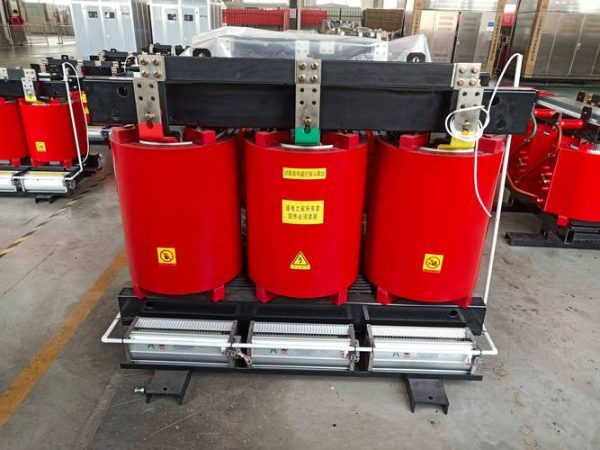
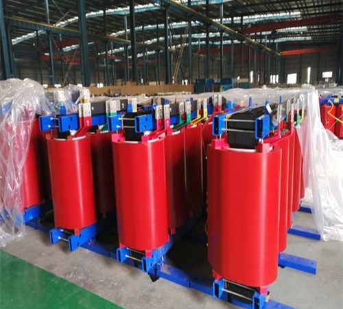
SCB11-2500/35 is a 2,500 kVA three-phase cast resin dry-type transformer with a 35 kV primary and a 0.4 kV secondary — a 3,608 amp low-voltage source built for indoor, fire-sensitive sites. This page gives the loss table, the 35 kV insulation caveats, the enclosure and cooling trade-offs, and the three applications where a dry 35 kV unit is the wrong answer.
Standards referenced on this page: IEC 60076-11 / GB/T 1094.11 (dry type), IEC 60076-3 (insulation levels), IEC 60076-5 (short-circuit withstand), IEC 60076-10 (sound), IEC 60270 (partial discharge), GB/T 10228-2015 (Chinese dry-type performance limits), GB 20052 (China MEPS), NFPA 70 (NEC) Article 450. Listing and efficiency-regime status: [Confirm] per destination market.
1. What This Unit Is
An SCB11-2500/35 is an epoxy resin vacuum-cast, air-cooled transformer: no oil, no liquid dielectric, no oil containment, no fire-rated transformer vault in the classic sense. At 2,500 kVA on a 35 kV primary it sits at the top of the practical envelope for cast resin construction, and that single fact drives most of the engineering decisions on this page.
Two things buyers usually get wrong before the first RFQ. First, “11” is a loss-level design code, not an energy-efficiency grade — see section 2. Second, a 35/0.4 kV unit is a low-voltage source: it does not step down to 10 kV, and it cannot feed a 10 kV bus (section 6). Get the voltage ratio right on the RFQ and half the downstream problems disappear.
The honest positioning: buy this transformer when fire safety, indoor siting, and no-liquid maintenance are the binding constraints — hospitals, high-rise plant rooms, tunnels, water treatment, large commercial LV load centres. Buy oil-immersed when you need outdoor duty, higher kVA, or the lowest capital cost per kVA, and run the loss numbers before you decide either way.
2. Decoding the Type Code
| Field | Stands for | What it actually tells a buyer |
| S | Three-phase | D would mean single-phase |
| C | Solid insulation — epoxy resin cast under vacuum | No flammable liquid; fire behaviour is governed by IEC 60076-11 class F1, not by the resin marketing name |
| B | Foil winding — copper foil | In practice the foil winding is the low-voltage winding. At 35 kV the HV winding is normally disc or layer type. Ask the factory which windings are foil and whether they are copper or aluminium [Confirm] |
| 11 | Loss-level design code | Not an efficiency grade. Confirms nothing about GB 20052 compliance on its own (section 3) |
| 2500 | Rated power, kVA | 2,500 kVA is a standard three-phase rating in both IEC and ANSI practice |
| 35 / 0.4 | HV / LV rated voltage, kV | North America: 34.5 kV class primary, 480Y/277 V secondary (section 13) |
One contradiction worth flagging in the source data: the type code says B = copper foil, while the application notes describe aluminium foil as a harmonic weakness. Those are different windings with different termination requirements. Aluminium foil LV windings need bimetallic transition treatment and specific jointing compound; copper foil does not. Put the winding material in the purchase specification, not in the brochure.
3. Key Performance Parameters: SCB11 vs SCB14 at 2,500 kVA
Published values below; every number must be confirmed against the type-test report for the exact unit you are buying.
| Parameter | SCB11 (as published) | SCB14 comparison | What to verify before you sign |
| No-load loss P0 | 3,650 W or less | 2,900 W or less (−20%) | Measured per IEC 60076-1; tolerance per the applicable standard [Confirm] |
| Load loss Pk | 19,700 W or less at 120 °C | 18,500 W or less (−6%) | Confirm the reference temperature. GB/T 10228 quotes Class F load loss at 120 °C; many IEC-based tenders use 75 °C (section 11) |
| Short-circuit impedance | 6%–8% | Same range | 2,500 kVA at 35 kV typically lands at 6.0%–7.0%. This sets your LV fault level — see section 6 [Confirm] |
| Insulation system | Class F (155 °C) | Class H (180 °C) optional | Temperature class and temperature rise are two different things (section 11) |
| Partial discharge | 10 pC or less | 5 pC or less | Acceptance is per IEC 60270 in a screened room. At 36 kV Um, 10 pC is a demanding but achievable limit (section 5) |
| Sound level | 65 dB or less | 60 dB or less | Ask whether this is sound power LWA or sound pressure at 1 m. They differ by roughly 11 dB in free field (section 9) [Confirm] |
| Temperature rise | 100 K average winding (Class F) | Same | Per IEC 60076-11 / GB/T 1094.11 by resistance method [Confirm] |
| Weight / dimensions | Not published | Not published | Needed for floor loading, rigging and door clearances. [Confirm] — a 2,500 kVA 35 kV cast unit is a multi-tonne assembly |
On the energy-efficiency claim: “11 = GB grade 3” is a shorthand that needs checking, not repeating. GB/T 10228-2015 sets dry-type performance and loss limits; the grading lives in GB 20052 (China’s minimum energy performance standard). Grade 3 in GB 20052 is normally the admission threshold, not a badge — if this unit’s P0/Pk exceed the grade-3 limit for 2,500 kVA dry-type, it is not sellable into a market that enforces MEPS. Verify the current standard version, whether 35 kV dry-type is in scope, and which grade the measured values actually fall into. [Confirm: GB 20052 grade and scope]
For context on where the series sits, the SCB14 dry-type range is the current-generation comparison most buyers ask for.
4. What the Losses Actually Cost You
Total annual energy is E = P0 x 8760 + Pk x beta^2 x 8760, where beta is the average load factor. At beta = 0.6 and $0.12/kWh:
| Item | SCB11 | SCB14 |
| No-load: P0 x 8,760 h | 3.65 kW x 8,760 = 31,974 kWh | 2.90 kW x 8,760 = 25,404 kWh |
| Load: Pk x 0.36 x 8,760 h | 19.70 kW x 0.36 x 8,760 = 62,126 kWh | 18.50 kW x 0.36 x 8,760 = 58,342 kWh |
| Total per year | 94,100 kWh | 83,746 kWh |
| Cost per year @ $0.12/kWh | $11,292 | $10,049 |
The SCB14 saves about 10,350 kWh a year — roughly $1,242/year, around $24,850 over 20 years at today’s tariff and flat escalation. That is real money, but it is not automatic justification: compare it against the SCB14 price premium and your actual load factor. At beta = 0.25 (a lightly loaded intake), the no-load term dominates and the premium pays back faster; near full load, the modest 6% load-loss difference carries most of the benefit.
There is a second number hiding in that table that every mechanical designer needs: average losses at beta = 0.6 are about 10.7 kW, and at full load about 23.4 kW. All of that leaves as heat into the room. Ventilation sizing is not an afterthought on a 2,500 kVA dry unit (section 10).
5. Why 35 kV Cast Resin Sits at the Edge of the Envelope
Cast resin dry-type transformers are mainstream at 10–24 kV. At 36 kV maximum system voltage — the top of the IEC 60076-11 range for cast resin insulation systems — you are asking a solid insulation system to do something it does with much less margin. Three consequences:
- Everything depends on the impregnation and casting process. Voids, delamination and poor resin penetration are what show up as partial discharge, and partial discharge is what kills cast resin HV windings over time. At 35 kV, factory process quality matters more than any line item on the datasheet.
- Insulation coordination changes. IEC practice for 36 kV typically calls for a BIL of 170 kV; North American 34.5 kV class equipment is commonly specified at a 200 kV BIL. [Confirm per IEEE C57.12.00 / IEC 60076-3 for the actual system] That difference is not cosmetic — it changes clearances, bushing selection, and whether an IEC-designed unit is acceptable to the authority having jurisdiction.
- Ask for evidence, not adjectives. Request the type-test certificate covering the same Um and BIL, the IEC 60270 partial discharge report, and the factory’s shipped-unit count at 35 kV. A supplier who has built a handful of 35 kV cast units is a different risk from one who has built hundreds.
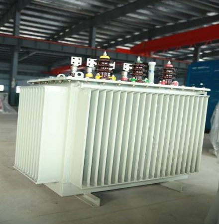
If the site is outdoor, industrial, or above roughly 2,500 kVA, price the 35 kV oil-immersed alternative in parallel. At this size, oil-immersed is usually cheaper per kVA, easier to cool outdoors, and better documented for short-circuit duty.
6. Application 1: 35 kV Industrial Intake — Check the Voltage Ratio First
Large industrial sites (chemical, cement, steel, mining) typically take 35 kV and distribute at 10 kV or 6 kV, with local 400 V substations near the load. A 35/0.4 kV transformer serves the 400 V load centre, not a 10 kV bus. If your single-line shows a 35 kV supply feeding a 10 kV switchboard, you need a 35/10 kV unit, not this one. This is the single most common RFQ error on 35 kV projects, and it is only caught at the drawing review stage if someone catches it at all.
Two numbers to run before the cable schedule:
| Check | Value at 2,500 kVA | Why it matters |
| LV rated current | 3,608 A at 400 V; 3,007 A at 480 V | Above roughly 2,000 A you are designing busway, not parallel cable runs — terminal box, neutral sizing and bend radii all change |
| LV prospective fault current | Roughly I_rated / Z = 3,608 / 0.06 ≈ 60 kA | Every downstream panelboard, MCC and busway section needs a short-circuit current rating above this (less utility source impedance). [Confirm: calculate properly with the full network impedance] |
Choose the impedance deliberately. Low impedance (6%) gives better voltage regulation but a higher fault level and more expensive downstream gear; 7%–8% costs a little regulation and buys you cheaper switchgear. This is a whole-project cost decision, not a transformer-only one.
7. Application 2: Solar and Wind Step-Up, and the 5 MW Sizing Trap
A 2,500 kVA unit at 0.95 power factor carries about 2,375 kW of AC output. A “5 MW” PV or wind block needs roughly 5.5–6.3 MVA of transformer capacity once you account for inverter continuous rating and clipping behaviour. So 2,500 kVA is a ~2–2.5 MW block, not a 5 MW plant. If the source application note says “suitable for plants up to 5 MW” and the single-line shows one 2,500 kVA transformer, the design clips generation every sunny afternoon at peak.
Three further cautions for renewable duty:
- Step-up duty is normally outdoor. An outdoor 35 kV cast resin unit needs IP54 or better, anti-condensation heaters, and a derating allowance — and then has to reject ~23 kW of full-load heat through that enclosure (section 10). Most renewable step-up installations use oil-immersed ONAN units or a packaged compact substation for exactly this reason.
- Inverters are converters, not linear loads. PWM switching gives you high-frequency common-mode and differential stress on the winding insulation, plus harmonic heating. Specify the duty to IEC 61378-1 (converter transformers) or an IEEE C57.110 K-factor, and consider an electrostatic shield between windings where inverter manufacturer practice requires it. [Confirm with the inverter OEM]
- No overload buffer. Dry-type windings have small thermal mass. An inverter that runs 1.1x nameplate on a cool, high-irradiance day has no oil volume to absorb it.
8. Application 3: Replacing an Oil-Filled Unit
The retrofit case is real and often wins — but “same rating, same footprint, reuse the foundation” is a claim to verify, not to assume.
| What changes | In practice |
| Mass and footprint | Do not assume parity. Get certified dimensional and mass drawings; cast resin units at this size are heavy and tall. [Confirm] |
| Door and hatch clearances | A 2,500 kVA 35 kV cast unit is frequently 2.2–2.6 m tall. Existing plant-room doors and hatches are the usual blocker [Confirm] |
| Heat rejection | Oil carries heat to radiators, often outdoors. A dry unit dumps all of it into the room — you are adding ventilation, possibly air conditioning [Confirm] |
| Fire provisions | Removing oil removes bunding, oil-filled equipment fire separation and drain requirements. But dry-type over 112.5 kVA triggers its own room/fire-separation rules under NEC 450.21(B) — [Confirm with the AHJ] |
| Protection | Drop the Buchholz relay and winding-temperature oil alarm; add winding RTD/PTC protection, forced-air fan control, and enclosure door interlocks |
Ventilation is the item that sinks retrofits. Before you commit, have someone size the room air change rate against full-load losses with the enclosure you intend to buy, and check the intake path. If the room cannot reject 23 kW, the transformer will run hot regardless of what the datasheet says.
For a fuller treatment of the medium, see oil-immersed vs dry-type: how to choose.
9. Where the “Do Not Use” List Is Right — and Where It Is Wrong
The source notes list three disqualifying conditions. Two of them are directionally useful and poorly worded; one is simply wrong.
| Claim | Verdict | What to specify instead |
| “High humidity / coastal / mining: resin cracks” | Overstated. Cast resin dry-type is specifically qualified for this — IEC 60076-11 defines climate class C2 (condensation and pollution) and environmental class E2 | The real failure mode is conductive dust or salt on a surface that is never cleaned, which leads to tracking. Specify C2/E2, an IP54 enclosure with anti-condensation heaters, and a cleaning interval |
| “High harmonic load (THDi > 15%): foil windings are weak” | Right conclusion, wrong mechanism. Harmonics do not attack “foil”; they add eddy and stray losses and raise the winding hot spot. Specify IEEE C57.110 K-factor or IEC 61378-1 duty and derate accordingly (section 12) | |
| “Fire-sensitive areas: epoxy releases toxic gas — use SCB13 or higher flame-retardant formula” | Careful is right, the fix is wrong. Epoxy is organic; it burns and it smokes. Compliance is demonstrated by the IEC 60076-11 fire class F1 type test (ideally with C2 and E2), and that is a test result for a design, not a function of the series number. Moving from SCB11 to SCB13 changes losses, not fire classification |
On the “SCB13 or above” point specifically: the SCB13 series is a lower-loss design, and buying it for energy reasons is sensible. Buying it for fire reasons is not — ask for the F1 certificate either way.
And on noise: 65 dB is not self-describing. If it is sound power level LWA (the type-test declaration under IEC 60076-10), free-field sound pressure at 1 m is roughly LWA minus 11 dB, and a hard-walled plant room pushes measured levels back up. If it is sound pressure at 1 m, say so on the datasheet. Ask which, and make the manufacturer state the forced-air (AF) value separately — fans typically add several dB. [Confirm: LWA vs Lp, and AF value]
10. Enclosure, IP Rating and the Cooling Conflict
| Enclosure | Protects against | Cost |
| IP00 (bare unit) | Nothing — indoor locked room only | Best cooling, cheapest, no touch protection |
| IP20 | Fingers and tools; no water protection at all (second digit 0) | Indoor plant rooms; slight derating possible [Confirm] |
| IP23 | Water sprayed up to 60 degrees from vertical | Not outdoor. Semi-sheltered locations only |
| IP54 | Dust and splashed water from any direction | Outdoor or washdown — but traps heat. Typically 10%–25% derating unless you add filtered forced ventilation [Confirm: derating factor with the factory] |
There is a genuine tension here and it is worth stating plainly: the enclosure that protects the transformer from the environment also stops it from shedding heat. A sealed IP54 enclosure around a 2,500 kVA unit has to move roughly 23 kW at full load. Filtered forced ventilation solves it and reintroduces two problems — filters clog with the dust you were excluding, and fans add noise and a failure mode.
Also treat forced-air capacity honestly. AF typically lifts a cast resin unit by about 1.4–1.5x the AN rating, but that capacity vanishes when the fans fail. Never count AF capacity as firm capacity in an N+1 scheme. On noise-sensitive floors, specify that fans start on winding temperature, not on load. See dry-type transformer: what it is and how to choose one for the enclosure-versus-derating trade-off in more depth.
11. Insulation Class, Temperature Rise and the 120 °C Reference
Three separate numbers get conflated in quotes, and conflating them costs money:
- Insulation class (Class F = 155 °C, Class H = 180 °C) is the thermal capability of the insulation system.
- Temperature rise (100 K average winding rise for Class F) is measured by the resistance method per IEC 60076-11 / GB/T 1094.11.
- Reference temperature for load loss is a convention, and conventions differ. GB/T 10228 quotes Class F load loss at 120 °C; many IEC-based and North American tenders use 75 °C.
That last one is not pedantry. For copper windings, resistance scales as (234.5 + T) / (234.5 + 75), so the same winding quoted at 120 °C instead of 75 °C shows roughly 14.5% more I²R loss. Two quotes can differ by double digits purely because of the reference temperature. Normalise before comparing. [Confirm the reference temperature on every quote you receive]
One thing not to do: do not carry the oil-immersed “10 K rule” (every 10 K above the hot spot halves insulation life, per IEEE C57.91) across to epoxy. That ageing curve belongs to cellulose insulation in oil. Dry-type ageing follows the thermal class guidance in IEC 60076-11; overloading behaviour and emergency ratings should be taken from the manufacturer’s loading guide for that insulation system. [Confirm]
12. Harmonics and Converter Duty
Harmonic current does not care whether the winding is foil or wire. What it does is drive additional eddy loss in the windings and stray loss in structural parts, which raises the hot spot above what the 120 °C load-loss figure implies. The standard machinery for this is IEEE C57.110 (K-factor definition and derating procedure) or IEC 61378-1 for converter-duty transformers.
Practical sequence:
- Measure or model the actual harmonic spectrum at the point of common coupling — current THD alone is not enough; the harmonic order distribution matters, because eddy loss scales roughly with the square of harmonic frequency.
- Decide whether you need a K-rated or converter-duty design, or simply a derated standard unit. Derating a standard transformer is often the cheaper answer.
- Confirm the neutral and any delta tertiary sizing if triplen harmonics are significant.
Worth knowing before you pay for K-rating: on one hyperscale data centre project we reviewed, the measured spectrum did not justify K-rated transformers at all — modern IGBT rectifiers often produce THD well under 5%. That review is documented here: K-factor rated dry-type transformers for a hyperscale data centre.
13. North America: 34.5 kV, 480Y/277 V, 60 Hz
| Source design | North American equivalent | Comment |
| 35 kV | 34.5 kV class | Not a like-for-like swap: BIL, creepage, and protection coordination all need recalculating [Confirm] |
| 0.4 kV | 480Y/277 V (600Y/347 V in Canada) | 2,500 kVA at 480 V = 3,007 A |
| 50 Hz | 60 Hz | Must be stated at RFQ. It cannot be changed afterwards |
| Dyn11 | Dyn1 on ANSI drawings | Same vector group, different notation |
| GB/T 10228 | IEC 60076-11 / IEEE C57.12.01 | Expect to re-submit dielectric and temperature-rise evidence |
On 60 Hz: a 50 Hz design run at 60 Hz is generally thermally safe but its guaranteed losses, impedance and sound level no longer hold, and vice versa. Design the core for the system frequency you actually have.
On efficiency regulation: US distribution transformer efficiency is governed by DOE 10 CFR Part 431, Subpart K (§431.196 low-voltage dry-type, §431.198 medium-voltage dry-type) — not 10 CFR 430, which covers consumer products. Whether a 34.5 kV, 2,500 kVA dry-type unit falls in scope needs checking against the current definition, because DOE coverage is bounded by voltage class and kVA. [Confirm: DOE scope for this rating] If it falls outside the federal regime, energy performance has to be enforced contractually: put P0 and Pk limits in the purchase document and evaluate bids on capitalised losses, not on purchase price alone.
The standards mapping itself is worth reading before you issue an RFQ: IEC 60076 vs ANSI/IEEE standards for export transformers.
14. Standards and Compliance Checklist
| Standard | Governs | What to ask the supplier for |
| IEC 60076-11 / GB/T 1094.11 | Dry-type ratings, temperature rise, dielectric, classes F1 / C2 / E2 | Type test report at the same Um and BIL |
| IEC 60076-3 / IEEE C57.12.00 | Insulation levels and dielectric tests | BIL/BSL confirmation for the actual system voltage |
| IEC 60076-5 | Short-circuit withstand | Calculation or test evidence for this rating |
| IEC 60076-10 / -10-1 | Sound power level determination | LWA declaration, and a separate AF value |
| IEC 60270 | Partial discharge measurement | Factory PD report with test circuit and acceptance level |
| GB/T 10228-2015 | Chinese dry-type performance and loss limits | Cross-check against the IEC-quoted values |
| GB 20052 | China MEPS energy grades | Confirm current version, grade and 35 kV scope [Confirm] |
| DOE 10 CFR 431 Subpart K | US distribution transformer efficiency | Confirm applicability for this rating [Confirm] |
| NFPA 70 (NEC) 450.21(B), 450.22 | Dry-type installation and fire separation | AHJ sign-off on the room [Confirm] |
| ISO 12944 | Enclosure corrosion protection, C4/C5 | Coating specification for coastal or industrial atmospheres |
UL listing is a separate question from IEC compliance and is not implied by any of the above. If the project requires a UL Listed (as opposed to Recognized component) dry-type transformer, say so in the RFQ and budget for it — retrofitting a listing does not happen. [Confirm: listing status and scope]
More background on how these standards are applied in practice is in our resource library.
15. Specifying and Commissioning: A Short Checklist
- Freeze the system voltages and frequency first: 34.5 kV or 35 kV, 480Y/277 V or 400 V, 60 Hz or 50 Hz, vector group, and earthing arrangement.
- Set the impedance from the downstream fault level and equipment SCCR, not from habit.
- Write P0 and Pk limits into the enquiry with the reference temperature stated (75 °C or 120 °C), and ask for capitalised-loss evaluation.
- Require the type-test package: temperature rise, dielectric, partial discharge, sound power, short-circuit withstand.
- Confirm the enclosure IP rating and the derating that comes with it, in writing, before ordering.
- Size room ventilation against full-load losses with the enclosure installed.
- State the harmonic duty: K-factor, converter duty per IEC 61378-1, or a declared spectrum with a derating.
- Plan the lift: mass, dimensions, transport height, door widths, and a rigging method. Confirm the transport tilt limit with the factory [Confirm: tilt limit, commonly 15 degrees for oil-immersed units].
- On site: insulation resistance and polarity checks before energisation, torque check on all LV terminations, functional test of RTDs, fan control, alarms and door interlocks.
- Keep the type-test and factory test reports in the O&M file — you will need them for insurance and for the next engineer who inherits the plant.
16. FAQ
Is SCB11 still worth buying, or should I go straight to SCB14? Buy SCB11 when you are replacing an identical unit on an existing base, when you need a fast replacement from stock, or when the destination market does not enforce MEPS and your load factor does not justify the premium. Otherwise get both quoted and let the loss calculation decide — at beta = 0.6 the SCB14 saves about $1,242 a year at $0.12/kWh, so the question is simply whether the SCB14 price premium pays back inside your evaluation period.
Does “11” mean grade 3 energy efficiency? No. “11” is the manufacturer’s loss-level design code. The grading lives in GB 20052, and grade 3 is typically the admission threshold rather than an achievement. Ask the supplier to state the measured P0 and Pk against the current GB 20052 limits for 2,500 kVA dry-type, and confirm whether 35 kV dry-type is in scope. [Confirm]
Can this transformer run outdoors on a solar or wind site? Not as a bare unit. A cast resin transformer outdoors needs an IP54 enclosure at minimum, plus anti-condensation heaters and a derating allowance — and it has to reject roughly 23 kW of full-load heat through that enclosure. Outdoor renewable step-up is usually better served by an oil-immersed ONAN unit or a packaged compact substation.
What does 65 dB actually mean on the datasheet? Ask whether it is sound power level LWA under IEC 60076-10 or sound pressure at 1 m. In free field, sound pressure at 1 m is roughly LWA minus 11 dB, and a hard-walled plant room pushes measured values back up through reflection. Also ask for the forced-air (AF) figure separately, because fans typically add several dB. [Confirm]
Can a 35/0.4 kV transformer feed a 10 kV busbar? No. The secondary is 400 V (480Y/277 V in North America). If your single-line shows 35 kV feeding a 10 kV or 13.8 kV switchboard, you need a 35/10 kV or 34.5/13.8 kV transformer. This comes up surprisingly often on industrial retrofit projects.
Is 2,500 kVA right for a 5 MW solar plant? No. At 0.95 power factor it carries about 2,375 kW, so it is a 2–2.5 MW block. A 5 MW section typically needs 5.5–6.3 MVA of transformer capacity depending on inverter continuous rating and clipping strategy. Size from the inverter nameplate output, not from the DC array rating.
Is it a drop-in replacement for an oil-immersed unit of the same rating? Sometimes, but do not assume it. Verify mass, footprint and floor loading, check that it fits through the existing door and hatch openings, and size the room ventilation for the full-load losses, because a dry unit dumps all its heat into the room instead of into outdoor radiators. Removing oil also removes bunding and oil-fire provisions — but dry-type over 112.5 kVA brings its own separation requirements under NEC 450.21(B). [Confirm with the AHJ]
Do I need a K-rated transformer for my harmonic load? Only if the spectrum says so. Measure or model it first: modern IGBT rectifiers frequently sit under 5% THD and need no K-rating at all. Where the spectrum is genuinely dirty, IEEE C57.110 gives the K-factor and the derating procedure; IEC 61378-1 covers converter duty. Derating a standard unit is often cheaper than buying a K-rated one.
Why do two suppliers quote different load losses for the same rating? Frequently it is the reference temperature, not the design. GB/T 10228 quotes Class F load loss at 120 °C; many tenders use 75 °C. For copper, that difference alone moves the I²R term by about 14.5%. Normalise every quote to one reference temperature before comparing. [Confirm the reference on each quote]
What do you need from me to quote a 2,500 kVA 35 kV dry-type transformer? System voltages and frequency, vector group and earthing, required impedance and the downstream fault level, load profile or expected load factor, harmonic spectrum if the load is non-linear, indoor or outdoor and the enclosure IP rating, ambient temperature and altitude above 1,000 m, enclosure coating class (ISO 12944 C4/C5 if coastal or industrial), applicable standards and any UL or DOE requirement, and the site access constraints for delivery and rigging.
17. Three Ways to Move Forward
- Get the parameter sheet and RFQ template — the full 2,500 kVA data package, including the P0/Pk limits and the type-test list to demand. [Confirm: document URL]
- Run your own loss comparison — send us your load profile and tariff and we will return the 20-year capitalised-loss comparison for SCB11, SCB13, SCB14 and the amorphous option. [Confirm: calculator URL]
- Talk to an application engineer — send the single-line and the room dimensions before you freeze the spec. The 35 kV clearances, the LV fault level and the ventilation requirement are far cheaper to fix on paper than on site.
Browse the full product range, or look at comparable delivered projects to see how these decisions played out on real sites.