
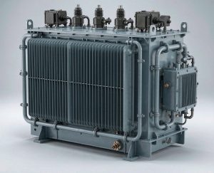
Rail electrification demands transformers that survive continuous vibration and shock in a tight installation envelope while meeting railway fire and safety rules. We build onboard traction transformers for {25 kV 50 Hz, 15 kV 16.7 Hz, 2 × 25 kV and 60 Hz} systems, auxiliary transformers for signalling, HVAC and station loads, and trackside traction substation units for DC metros. Engineered to IEC 60310, qualified to IEC 61373, fire performance to EN 45545-2.
Why rail duty cannot be met with an adapted utility design
1. Continuous vibration and shock
A rolling stock transformer is mounted under the frame, where it sees continuous broadband vibration plus shock from track joints, switches and coupling, for thirty years. We design the core-and-coil as a single clamped mass with resonance kept clear of the excitation band, treat every lead and bushing as a fatigue problem rather than a connection, and qualify the finished unit to IEC 61373 — typically category {1, class B} for underframe-mounted equipment. Vibration qualification is a type test, not a calculation.
2. Fire, smoke and toxicity
On passenger rolling stock, fire behaviour is usually the hardest requirement to clear. EN 45545-2 sets hazard levels HL1 to HL3 and limits flame spread, smoke density and toxicity — and a conventional mineral-oil-filled transformer rarely clears it. That is why onboard traction transformers are normally specified with synthetic ester (IEC 61099) or natural ester (IEC 62770) fluid, whose fire point is far above mineral oil’s, or as dry-type cast resin units for indoor station duty.
3. Weight and installation envelope
Underfloor volume is fought over by traction, braking and HVAC, and every kilogram on a high-speed trainset costs energy for its whole life. We design to a mass budget rather than to a cost budget: aluminium windings where the envelope allows, high-temperature insulation systems that permit a higher rise in a smaller core, and cooling matched to the actual duty rather than to a standard frame size.
4. Insulation coordination across supply systems
Rail supply voltages are not interchangeable. A {16.7 Hz} transformer is physically heavier than an equivalent {50 Hz} one because core flux scales inversely with frequency, and DC-electrified networks need no onboard traction transformer at all. Insulation coordination follows EN 50124-1 rather than general IEC 60076 practice, with clearances and creepage set for the traction environment. Getting this wrong at enquiry stage is the single largest source of redesign on rail projects.
Technical specifications
| Parameter | Specification |
|---|---|
| Product families | Onboard traction transformer · auxiliary / hotel power transformer · trackside traction substation transformer · station service transformer |
| Rated power (onboard) | {1 – 12 MVA} for traction · {10 – 400 kVA} for auxiliary windings and sets |
| Primary voltage | {25 kV} · {15 kV} · {2 × 25 kV AT} · {12.5 / 25 kV 60 Hz} · other per IEC 60850 / EN 50163 |
| Supply frequency | {16.7 Hz} · 50 Hz · 60 Hz |
| Traction secondaries | {2 – 8} separate windings for four-quadrant converter feed · galvanically separated to limit converter interaction |
| Auxiliary / hotel winding | {300 – 400 V} for train services, HVAC, compressors and battery charging |
| Cooling | ONAN · ONAF · forced oil (OF / OFAF) with integrated pump and heat exchanger · dry-type AN / AF |
| Insulating medium | Synthetic ester IEC 61099 · natural ester IEC 62770 · mineral oil IEC 60296 (trackside and freight) · cast resin IEC 60076-11 |
| Winding conductor | Aluminium or copper · high-temperature insulation system, class {180 / 200} |
| Insulation coordination | EN 50124-1 / IEC 62497-1 — clearances and creepage for traction environment |
| Vibration and shock | IEC 61373, category {1 class B} typical for underframe mounting |
| Fire performance | EN 45545-2, hazard level {HL1 / HL2 / HL3} per vehicle and operating environment |
| Ingress protection | {IP54 / IP55} per IEC 60529 for underframe equipment |
| Monitoring | Winding and oil temperature sensors, flow and pressure indication, Buchholz or equivalent, interfaces to train TCMS |
| Service life | {30 years} design life · RAMS documentation to EN 50126 |
| Mass | state kg per rating and envelope drawing reference |
Traction supply systems and the transformer each one needs
Nominal systems per IEC 60850 / EN 50163. Confirm the supply system at enquiry stage — it drives core size, insulation and the entire mechanical design.
| Supply system | Nominal | Where it is used | Transformer implication |
|---|---|---|---|
| 25 kV AC | 25 kV, 50 Hz | Europe, China, India, UK, most new high-speed | Standard onboard traction transformer; AT feeding on high-speed lines |
| 2 × 25 kV autotransformer | 50 kV catenary-to-feeder, 25 kV to train | High-speed lines: China, France, Spain, Italy, Japan | Onboard unit still 25 kV; trackside autotransformers along the line |
| 15 kV AC | 15 kV, {16.7 Hz} | Germany, Austria, Switzerland, Sweden, Norway | Low frequency → larger, heavier core for the same rating |
| 12.5 / 25 kV, 60 Hz | 60 Hz | North America, parts of Japan and Korea | 60 Hz design; lighter core than 16.7 Hz |
| 3 kV DC | 3 kV DC | Italy, Poland, Belgium, Russia, South Africa | No onboard traction transformer — DC feeds converters directly; onboard auxiliary via static converter; trackside rectifier transformers |
| 1.5 kV DC | 1.5 kV DC | France, Netherlands, Japan, parts of India | Trackside rectifier transformers, usually 12- or 24-pulse |
| 750 / 1500 V DC | DC third rail or overhead | Urban metro and light rail worldwide | Trackside traction rectifier transformers plus station auxiliary units |
Three product families, three different design problems
| Family | Onboard traction | Auxiliary / hotel power | Trackside substation |
|---|---|---|---|
| Location | Underframe or roof of the vehicle | Onboard winding or separate station unit | Trackside substation, depot or station building |
| Typical rating | {1 – 12 MVA} | {10 – 400 kVA} | {2 – 40 MVA} rectifier and autotransformers |
| Primary | {15 / 25 kV} AC | {15 / 25 kV} or LV station supply | {10 – 110 kV} utility supply |
| Governing standard | IEC 60310 | IEC 60310 / IEC 60076 | IEC 61378-1 converter transformers |
| Dominant constraint | Mass, envelope, vibration, fire | Continuity of supply for signalling and HVAC | Footprint, harmonics, cooling and access |
| Fire behaviour | EN 45545-2 — ester fluid or dry-type | EN 45545-2 onboard; IEC 60076-11 F1 for stations | Local building and fire code |
| Harmonic duty | Four-quadrant converter feed | Low | 12- or 24-pulse rectifier configuration |
Insulating fluid and fire behaviour
| Medium | Characteristics | Typical assignment |
|---|---|---|
| Mineral oil IEC 60296 |
Lowest cost, best heat transfer, well proven | Fire point around {160 °C} — generally not acceptable for passenger rolling stock under EN 45545-2. Used for freight locomotives and trackside units |
| Synthetic ester IEC 61099 |
Fire point well above {300 °C}, strong oxidation stability, readily biodegradable | Default for onboard traction transformers on passenger stock — usually the fluid that clears HL2 and HL3 |
| Natural ester IEC 62770 |
Fire point above {300 °C}, renewable source | Onboard and trackside where environmental criteria apply; higher viscosity needs checking against the cooling design |
| Cast resin dry-type IEC 60076-11 |
No liquid, class F1 fire behaviour, low smoke | Station and tunnel installations, indoor auxiliary units — larger and heavier per kVA |
Fluid choice is not a line-item decision: it determines whether the unit clears EN 45545-2, and it changes the thermal design, the gasket and paint specification, and the maintenance regime. Decide it before the envelope is frozen.
Testing, documentation and quality
| Stage | Scope |
|---|---|
| Type tests | Per IEC 60310 and IEC 60076 — temperature rise, dielectric, lightning impulse, short-circuit withstand to IEC 60076-5 |
| Vibration and shock | IEC 61373, category {1 class B} — random vibration and shock on the finished transformer, not simulated on a model |
| Fire performance | EN 45545-2 material and component assessment to the hazard level the vehicle requires |
| Routine tests | Per IEC 60076-1 on every unit, with individual test reports |
| Factory acceptance | Witnessed FAT available, including functional checks of cooling, protection and monitoring |
| Material certification | EN 10204 type {3.1} material certificates; welding to EN 15085 where applicable |
| RAMS and lifecycle | Failure mode analysis, maintainability and reliability data to EN 50126 |
| Quality system | ISO 9001 · ISO/TS 22163 (IRIS) — confirm certification status |
Compliance and standards
| Standard | Scope |
|---|---|
| IEC 60310 | Railway applications — traction transformers and inductors on board rolling stock |
| IEC 61373 | Railway applications — rolling stock equipment — shock and vibration tests |
| EN 45545-2 | Fire protection on railway vehicles — requirements for fire behaviour of materials and components |
| EN 50124-1 / IEC 62497-1 | Railway applications — insulation coordination |
| IEC 60850 / EN 50163 | Supply voltages of traction systems |
| EN 50121 / IEC 62236 | Railway applications — electromagnetic compatibility |
| EN 50155 / IEC 60571 | Electronic equipment used on rolling stock (auxiliary and control equipment) |
| EN 50126 | Railway applications — RAMS: reliability, availability, maintainability and safety |
| EN 15085 | Welding of railway vehicles and components |
| EN 50122-1 | Fixed installations — electrical safety, earthing and the return circuit |
| IEC 61378-1 | Converter transformers for industrial applications — trackside traction rectifier transformers |
| IEC 60076-5 / 60076-11 | Short-circuit withstand · dry-type transformers |
| IEC 60529 | Degrees of protection provided by enclosures (IP code) |
| ISO/TS 22163 (IRIS) | Railway quality management system — confirm certification status |
Frequently asked questions
What is a traction transformer and where is it installed?
It is the transformer that steps the overhead catenary voltage down for the train’s traction converters. On AC-electrified rolling stock it is usually mounted under the frame (underfloor) or occasionally on the roof, and it feeds several separate secondary windings, each supplying one four-quadrant converter, plus often an auxiliary winding for train services. Onboard units are designed to IEC 60310.
Why are some traction transformers built for 16.7 Hz?
Germany, Austria, Switzerland, Sweden and Norway supply their AC network at 15 kV and {16.7 Hz} instead of 50 Hz. Because core flux is proportional to voltage divided by frequency, a 16.7 Hz transformer needs roughly three times the core cross-section of an equivalent 50 Hz unit — so it is larger and heavier. That is not an inefficiency, it is physics, and it is why the supply system has to be fixed before the envelope is agreed.
Do DC metro trains need an onboard traction transformer?
Generally no. On 750 V, 1.5 kV and 3 kV DC systems the traction supply goes to the converter without a transformer, and the train carries auxiliary power conversion instead. The transformer work on a DC metro is trackside: rectifier transformers, usually 12- or 24-pulse, feeding the DC traction bus, plus station auxiliary transformers.
Why is ester fluid specified instead of mineral oil on rolling stock?
EN 45545-2 restricts flame spread, smoke density and toxicity on railway vehicles, and a mineral-oil-filled transformer with a fire point around {160 °C} rarely clears the required hazard level. Synthetic ester (IEC 61099) and natural ester (IEC 62770) have fire points well above {300 °C} and are the normal route to compliance for passenger stock.
How is vibration and shock qualification carried out?
The finished transformer is tested to IEC 61373, which defines categories and classes by mounting location — underframe-mounted equipment is typically category 1, class B. Random vibration and shock are applied on a shaker table, and qualification is a type test on the actual unit, not an analytical result.
Do you hold IRIS (ISO/TS 22163) certification?
State your actual certification status here. If you do not hold it, say “IRIS certification available on request” or “in progress” — never claim a certificate you cannot evidence. Our quality system is ISO 9001 certified and we supply full type, routine and FAT documentation with every unit.