
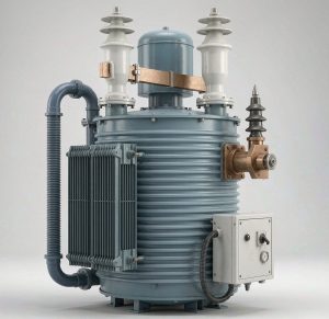
Electric arc furnaces, ladle refining and electrolysis loads punish a transformer with repeated short-circuit forces, rapid load swings and harmonic-rich current. Our furnace and rectifier transformers are built for that duty: reinforced core-and-coil construction, oversized bushings for tens of kiloamps of secondary current, and cooling rated for continuous overload. Ratings from {5 to 200 MVA}, secondary current up to {80 kA}, in 6- to 48-pulse rectifier configurations.
Why furnace and rectifier duty needs a purpose-built transformer
1. Short-circuit withstand — the event is routine, not exceptional
On an electric arc furnace the electrodes routinely strike the charge and collapse the secondary voltage into a virtual short circuit. That is a normal operating event, not a fault. We design accordingly: reinforced core-and-coil structure, heavy clamping frames and pre-stressed winding assemblies, continuously transposed conductor (CTC) to reduce radial forces, and winding layouts verified against IEC 60076-5 short-circuit withstand. Full short-circuit test reports are available for the relevant ratings.
2. Thermal duty at very high secondary current
Furnace secondaries carry tens of kiloamps at low voltage, so losses concentrate in the bushings, leads and tank walls rather than the windings alone. We use oversized bushings, low-resistance busbar take-offs, and non-magnetic or shielded steel in high-field regions to eliminate local hot spots. Cooling is sized to the duty cycle, not the nameplate — typically OFAF or OFWF, with overload capacity defined against the IEC 60076-7 loading guide.
3. Harmonic control on rectifier duty
A rectifier transformer does more than step voltage down: its phase-shifted secondaries decide which harmonics reach the grid. Pulse number is the primary lever — a 12-pulse arrangement cancels the 5th and 7th harmonics at the primary, a 24-pulse arrangement cancels through the 13th. Built to IEC 61378-1, with phase-shifting wound into the transformer rather than bought as external filtering.
4. Voltage regulation under load swings
Melt-down and refining stages pull the network around, and automated process lines cannot tolerate the resulting drift. Our SZ11 on-load tap-changer transformers hold output stable while fully energised, with tap changers specified to IEC 60214-1 and — where the furnace cycles hard — rated for the high mechanical endurance those duty cycles demand. Remote control and process integration are available for automated lines.
Technical specifications
| Parameter | Specification |
|---|---|
| Product types | Electric arc furnace (EAF) · ladle refining furnace (LF) · submerged arc · rectifier / converter transformers |
| Rated power | {5 – 200 MVA} (higher on request) |
| Primary voltage | {6 / 10 / 11 / 20 / 33 / 35 / 66 / 110 kV} per grid |
| Secondary voltage | {100 – 1,200 V} for furnace duty; per rectifier arrangement for DC duty |
| Secondary / DC current | Up to {80 kA} AC · up to {100 kA+} DC |
| Impedance voltage | {6% – 12%} furnace duty · {6% – 12%} rectifier duty · tuned to limit fault current and stabilise the arc |
| Tap changing | On-load (OLTC) to IEC 60214-1 · off-circuit (DETC) option · {±8 × 1.25%} to {±16 steps} |
| Rectifier pulse number | 6 / 12 / 24 / 48-pulse · integral or external phase-shifting |
| Short-circuit withstand | IEC 60076-5 · state test report reference per rating |
| Cooling | ONAN · ONAF · OFAF · OFWF · ODAF |
| Insulating fluid | Mineral oil to IEC 60296 · natural ester IEC 62770 or synthetic ester IEC 61099 where fire risk or environmental rules require |
| Winding conductor | CTC (continuously transposed conductor) · transposed and pre-compressed windings |
| Protection and monitoring | Buchholz relay, winding temperature indicator, oil temperature, pressure relief device, OLTC motor-drive and position feedback, optional RS485 Modbus / IEC 61850 to plant DCS |
| Accessories | Conservator or sealed / bellows design, series reactor, booster regulator, harmonic filter interface |
Matching the design to the duty cycle
Indicative ranges. Final design is built from your furnace cycle, electrode regulation and grid fault level.
| Duty | Electric arc furnace | Ladle refining furnace | Electrolysis / DC smelting |
|---|---|---|---|
| Typical rating | {20 – 200 MVA} | {5 – 40 MVA} | {5 – 120 MVA} |
| Secondary voltage | {100 – 1,200 V} | {100 – 400 V} | Set by rectifier arrangement |
| Current | Up to {80 kA} AC | High AC, frequent switching | Up to {100 kA+} DC |
| Impedance | {6 – 12%} — limits fault current, stabilises the arc | {5 – 8%} | {6 – 12%} |
| Tap changing | OLTC, very frequent operation | OLTC | OLTC plus booster / regulating transformer |
| Dominant stress | Repeated short circuits, flicker and load swings | Frequent energisation and switching | Continuous full load and harmonic heating |
| Typical cooling | OFAF / OFWF | ONAF / OFAF | OFWF / OFAF |
The duty cycle is the design input, not the nameplate. Two 60 MVA furnace transformers serving different melt cycles can legitimately differ in impedance, cooling and tap-changer endurance. Send us the cycle and we will size to it.
Rectifier pulse number: how many pulses do you need?
| Arrangement | 6-pulse groups / phase shift | Harmonics cancelled at primary | Typical application |
|---|---|---|---|
| 6-pulse | 1 group, 60° | None — 5th and 7th dominant | Small or legacy drives; usually needs external filtering |
| 12-pulse | 2 groups, 30° apart | 5th, 7th | Standard for electrolysis, chlor-alkali and general DC smelting |
| 24-pulse | 4 groups, 15° apart | 5th, 7th, 11th, 13th | Large aluminium potlines, hydrogen electrolysers, strict grid codes |
| 48-pulse | 8 groups, 7.5° apart | Through the 47th | Very large DC plants where the utility imposes tight THD limits |
On-load voltage regulation and the SZ11 series
SZ11 is the Chinese designation for a three-phase oil-immersed transformer with on-load tap changing (OLTC) at performance level 11 — internationally specified simply as an oil-immersed OLTC power transformer. Where a project documents the Chinese type code, we quote the equivalent IEC and IEEE parameters alongside it so the specification is unambiguous across markets.
| Option | Operating range | Suits |
|---|---|---|
| Off-circuit (DETC) | De-energised, typically ±2 × 2.5% | Commissioning or seasonal correction only |
| On-load (OLTC) | Under full load, {±8 × 1.25%} to {±16 steps} | Furnace duty, automated process lines, weak grids |
| OLTC + booster regulator | Extended range with fine resolution | Electrolysis and DC processes needing smooth current control |
Tap-changers are specified to IEC 60214-1 with mechanical endurance matched to the furnace cycle — EAF duties can demand {300,000+} operations between overhauls. Remote control, position feedback and integration to the plant DCS are available over Modbus, IEC 61850 or hardwired interfaces.
Cooling options for continuous overload
| Code | Method | Typical rating step | Use case |
|---|---|---|---|
| ONAN | Oil natural, air natural | Base rating | No auxiliaries, lowest maintenance; limited rating |
| ONAF | Oil natural, air forced (fans) | Base + {33 – 40%} | Common for ladle refining and moderate furnace duty |
| OFAF | Oil forced, air forced (pumps + fans) | Base + {50 – 60%} | Continuous overload, high continuous rating |
| OFWF | Oil forced, water forced | Highest per footprint | Confined plant rooms, hot climates, large DC plants |
| ODAF | Oil directed, air forced | Directed flow over windings | Very high ratings and hot-spot control |
Cooling step is selected from the duty cycle, not the rating plate. Where the furnace peaks well above its average, we size to the peak and let the cooling stages follow the load — the transformer then runs its hot-spot within IEC 60076-7 limits instead of burning insulation life on every melt.
Compliance and standards
| Standard | Scope |
|---|---|
| IEC 60076-1 / 2 / 3 | General requirements, temperature rise, insulation levels and dielectric tests |
| IEC 60076-5 | Ability to withstand short circuit — the governing standard for furnace duty |
| IEC 60076-7 | Loading guide for oil-immersed power transformers — overload and thermal ageing limits |
| IEC 61378-1 | Converter transformers — transformers for industrial applications (rectifier duty) |
| IEC 60214-1 | On-load tap-changers — performance and type tests |
| IEEE C57.12.00 / C57.12.10 / C57.12.90 | North American general requirements and test code for liquid-immersed transformers |
| IEEE C57.18.10 | Practices and requirements for semiconductor power rectifier transformers |
| IEEE C57.91 | Guide for loading mineral-oil-immersed transformers |
| IEC 60296 / 61099 / 62770 | Mineral oil, synthetic ester and natural ester insulating fluids |
| ISO 9001 / 14001 / 45001 | Manufacturer quality, environmental and OH&S management |
Frequently asked questions
What makes an electric arc furnace transformer different from a standard power transformer?
Three things: it is designed for repeated short circuits rather than occasional ones, it delivers very high current at low secondary voltage, and its impedance is deliberately high to limit fault current and stabilise the arc. The core-and-coil is clamped and pre-stressed against mechanical forces, and cooling is sized to the melt cycle rather than the nameplate.
Why do EAF transformers have higher impedance than distribution transformers?
Higher impedance limits the short-circuit current when the electrodes strike the charge, and it stabilises the arc so the melt is controllable. It also reduces flicker propagated back into the grid. That is why furnace units commonly sit at {6–12%} where a distribution transformer would be 4–6%.
How many pulses should a rectifier transformer have?
Match it to the harmonic limit your utility imposes. 12-pulse cancels the 5th and 7th and suits most electrolysis and DC smelting duties. 24-pulse cancels through the 13th and is the usual choice for large aluminium potlines and hydrogen electrolysers on a weak grid. Going higher adds cost and footprint for diminishing returns.
What does SZ11 mean?
SZ11 is the Chinese type designation for a three-phase oil-immersed transformer with on-load tap changing at performance level 11. In IEC and IEEE terms it is specified as an oil-immersed OLTC power transformer with defined loss levels, tap range and cooling. We quote both the Chinese code and the international parameters on request.
Can a furnace transformer run continuously overloaded?
Yes, within its designed cooling stages and the thermal limits of IEC 60076-7 — continuous overload consumes insulation life in proportion to hot-spot temperature. We size the cooling to the peak of your duty cycle so the rated overload is achieved without abnormal ageing. Ask us for the loading calculation for your specific cycle.
Mineral oil or ester fluid — which should we specify?
Mineral oil (IEC 60296) remains the default and is the lowest-cost option. Where the installation is indoors, close to process heat, or subject to strict environmental rules, natural ester (IEC 62770) or synthetic ester (IEC 61099) gives a much higher fire point and biodegradability, at higher first cost and slightly different thermal behaviour.
Running a furnace or smelting line? See the power-frequency furnace transformer → or request a custom specification.