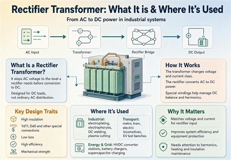
A rectifier transformer is a transformer built to feed a rectifier bridge, not to feed a building. It steps the grid voltage to whatever the diode or thyristor stack needs, then the bridge turns that AC into DC for a process that wants current, control, or both. The first thing to understand is that this unit is engineered around a nonlinear DC load. That single fact changes everything about how you specify it. Pulse count, phase shift, cooling, and short-circuit strength matter more than the nameplate kVA, and a standard distribution transformer of the same rating will not do the job.
This guide walks through what a rectifier transformer is, where they actually show up, how they differ from a plain power transformer, the pulse-number rule that governs harmonics, the real standards (and the one standard that does not apply), and a copy-ready spec clause you can drop into an RFQ.
What a rectifier transformer actually does
Picture the AC grid on one side and a big DC process on the other. The rectifier transformer sits between them. It does three jobs at once: change the voltage to the right level for the rectifier, isolate the grid from the DC side, and shape the windings so the bridge produces cleaner DC with fewer harmonics fed back into the line.
The rectifier itself can use diodes (one-way, no active control) or thyristors (controlled firing angle, so you can dial the output). Either way, the transformer is not a passive box. Its secondary windings are often split and phase-shifted on purpose. The design is selected around the converter, not the other way around.
That is the core difference from a general-purpose unit. A standard transformer assumes a roughly sinusoidal, balanced load. A rectifier transformer is designed for the exact opposite: distorted current, possible unbalance, and thermal stress from harmonics.
Where you will find them
If a process needs a serious, dedicated DC supply, a rectifier transformer is probably behind it. Here is the map.
| Application | Why it needs DC | Typical pulse count |
|---|---|---|
| Aluminum electrolysis | Electrolytic cells draw huge DC current at low voltage | 6 or 12 |
| Copper and zinc electrowinning | Metal recovery by electrochemical reduction | 6 or 12 |
| Chlor-alkali plants | Electrolysis of brine | 12 |
| Rail and metro traction substations | Feeds DC traction systems (often 1,500 V DC) | 12 |
| HVDC converter stations | Long-haul DC transmission at both ends | 12 or 24 |
| Electroplating and anodizing | Stable, uniform DC for coating thickness | 6 or 12 |
| Electric arc and ladle furnaces | DC arc with smooth control | 6 or 12 |
| Variable-frequency drive (VFD) inputs | Motor drives with common DC bus | 12, 18, or 24 |
| Battery and EV charging rectifiers | Controlled DC for charging | 6 or 12 |
| Electrostatic precipitators (ESP) | High-voltage DC for particulate capture | 6 or 12 |
The pattern is consistent. Anywhere you convert bulk AC into controlled DC at power levels that matter, this transformer is the unsung piece of steel doing the heavy lifting. For a look at how this plays out in a real transit project, see our auxiliary transformers for urban metro traction substations.
Rectifier vs standard power transformer: the real differences
People often ask whether they can just buy a standard transformer of the same kVA. The short answer is no, and here is why.
| Aspect | Standard power transformer | Rectifier transformer |
|---|---|---|
| Load current | Sinusoidal, balanced | Non-sinusoidal, can be unbalanced |
| Harmonics | Minimal, none by design | Built to carry and cancel them |
| DC bias | Saturates under any DC component | Tolerates it through balanced ampere-turns |
| Losses | Fundamental-frequency only | Adds harmonic load losses and higher hotspots |
| Insulation | Withstands power-frequency overvoltage | Reinforced for thyristor switching spikes |
| Short-circuit strength | Moderate | Reinforced for DC-side fault currents |
| Secondary windings | Single, three-phase | Multiple, phase-shifted |
| Cost at same kVA | Baseline | Roughly 40 percent higher in one published teardown |
That last line deserves a caveat. One published comparison of a 1,000 kVA unit found the rectifier version costing over 40 percent more, with about 15 to 20 percent higher no-load losses, 18 percent more copper, and 12 percent more silicon steel. Those are vendor-cited figures from a teardown, not a quotation, and your own project will vary. The point is structural: more copper, more steel, and more engineering because the unit earns its keep under abuse a standard design would not survive.
The pulse number is the whole ballgame
Here is the part most buyers underestimate. A “pulse” is one hump in the DC voltage waveform per AC cycle. More pulses means smoother DC and fewer harmonics pushed back into the grid. The characteristic harmonics of a p-pulse system follow a simple rule:
harmonic order h = 6k ± 1, where k = 1, 2, 3, ...
So a 6-pulse bridge throws out the 5th and 7th harmonics hardest. A 12-pulse system adds a second winding shifted 30 degrees, which cancels the 5th and 7th and leaves the 11th and 13th as the new lowest. Each time you double the bridges, the dominant harmonic jumps higher and the distortion drops.
| Pulses (n x 6) | Bridges | First dominant harmonic | Typical line-current THDi (no filter) |
|---|---|---|---|
| 6 | 1 | 5th, 7th | about 27 percent |
| 12 | 2 | 11th, 13th | about 13 percent |
| 18 | 3 | 17th, 19th | about 9 percent |
| 24 | 4 | 23rd, 25th | about 6 percent |
| 48 | 8 | 47th, 49th | about 3 percent |
The practical takeaway: a 6-pulse unit looks cheap on the bid sheet, but if your utility caps total harmonic distortion at the point of common coupling (often around 5 percent, as many grid codes do), that cheap unit can fail commissioning or rack up penalty charges. A 12-pulse design is the usual sweet spot. Beyond 24 pulses, passive or active filters usually beat adding more windings on cost. For the broader efficiency and cooling context behind these choices, our oil-immersed versus dry-type guide covers the medium tradeoffs.
Double-star vs double-bridge: the two winding families
Inside the tank, rectifier transformers come in two classic arrangements.
Double-star (sometimes written DSS) uses an interphase transformer between two star-connected secondaries. Each diode then conducts for 120 degrees. This is the workhorse for very high current at very low voltage, the kind of duty you see in aluminum potlines where secondary currents can reach 100 kA in published service data.
Double-bridge (DB) stacks more six-pulse bridges in parallel or series with precise phase shifts. This is how you get to 12, 24, 48, or even 60 pulses as harmonic control and process stability demand. The price is complexity: more windings, tighter phase-shift tolerance (a one-degree error in a 24-pulse design can wreck cancellation), and a bigger, costlier tank.
Neither is “better” in the abstract. The right family depends on your current level, voltage, and harmonic target.
Dry-type or oil-immersed?
Both cooling paths exist for rectifier duty, and the choice tracks the same logic as any transformer. Dry-type (cast-resin or VPI) wins indoors, in environmentally sensitive sites, and where fire safety matters. Oil-immersed wins at high capacity, outdoors, and where you need the cooling headroom that a fluid bath provides.
One wrinkle specific to rectifiers: harmonics raise the losses, which raises the hotspot temperature. That means the cooling system has to be sized for the harmonic-rich reality, not the nameplate. Wider cooling ducts, lower electromagnetic loading, and a comfortable temperature-rise margin are normal, not optional. Do not let a supplier quote you a standard cooling package and call it done.
Standards: IEC 61378 vs IEEE C57.18.10 (and why IEC 60076 is not enough)
This is where a lot of spec sheets get sloppy. You will see “compliant with IEC 60076” on rectifier transformers, and while that is not wrong for the general construction, it is incomplete. IEC 60076 is the family of standards for ordinary power and distribution transformers. It does not speak to converter duty the way a buyer needs.
The standards that actually govern this equipment:
| Standard | What it covers |
|---|---|
| IEC 61378-1:2011 | Converter transformers for industrial applications: thyristor and diode rectifiers for electrolysis, large drives, scrap-melting furnaces, and inverter-fed VFDs |
| IEEE C57.18.10-2021 | Semiconductor power rectifier transformers for dedicated loads rated 100 kW and above, single-phase or three-phase |
| IEC 60076 series | General power and distribution transformers. Useful but not the converter-specific rulebook |
| IEEE C57.12.x family | General power and dry-type transformers. Again, not the rectifier-specific standard |
| DOE 10 CFR 431 | U.S. efficiency rules for distribution and power transformers. Rectifier transformers are excluded from the federal definition |
The last row matters for U.S. buyers. Because rectifier transformers fall outside the federal distribution-transformer efficiency definition, they are not held to the same DOE efficiency floor as a standard unit. That is a double-edged sword: it gives you freedom to optimize the design for the process, but it also means you cannot assume a compliant label and must specify losses explicitly. Our special transformers page shows where rectifier units sit in the broader specialty family.
The DC-bias trap
Here is the failure mode that surprises people. A standard transformer core is designed around an AC flux. Push a DC component through it and the operating point walks up the saturation curve, the core overheats, and the unit can fail. Rectifier loads can create exactly that kind of asymmetry.
Rectifier transformers are designed against it from the start. The winding arrangement balances the ampere-turns so the DC component does not walk the core into saturation, and the magnetic circuit is built to survive the shock loads and inrush that come with thyristor firing. This is why “same kVA” is never a valid substitution. The nameplate number hides a completely different internal design.
Cooling and temperature rise under harmonics
Harmonic currents do not just sit in the windings. They drive eddy and stray losses in the tank, clamps, and laminations, all of which rise with frequency. The load loss you measure on site under rectifier duty will be higher than the factory sinusoidal test value. IEEE C57.18.10 gives calculation methods and worked examples for exactly this.
Practically, expect ONAN, ONAF, or OFWF cooling on oil units and forced-air or encapsulated dry-type construction indoors. The cooling class is not a footnote. It is part of how the unit survives a decade of non-sinusoidal life.
What a real spec clause should say
Vague language like “rectifier transformer, IEC compliant” tells a supplier nothing and protects you from nothing. Here is a clause you can adapt.
Rectifier transformer specification (minimum)
- Service: [electrolysis / traction / VFD / furnace / HVDC]
- Primary voltage: ___ kV   (50 Hz / 60 Hz)
- Secondary: ___ V, ___ kA DC, pulse number ___ (6 / 12 / 24)
- Vector group / phase shift: ___ (example: Dd0y11 for 12-pulse)
- Winding arrangement: [double-star / double-bridge / multiple secondary]
- Cooling: [ONAN / ONAF / OFWF / cast-resin dry-type]
- Impedance: ___ percent
- Harmonic target: THDi <= ___ percent at point of common coupling (reference IEEE 519)
- DC bias / unbalanced load: confirmed in writing with supplier
- Standards: IEC 61378-1:2011 (or IEEE C57.18.10-2021 for U.S. projects)
- Tests: routine per IEC 60076-3, plus loading with non-sinusoidal current
  and temperature rise under rectifier duty
Writing it this way forces the conversation that actually protects your budget: pulse count, phase shift, and harmonic target up front, not as a surprise at commissioning.
Buyer mistakes that cost real money
A few patterns show up again and again.
- Treating it like a standard transformer and buying on kVA alone.
- Picking 6-pulse to save money, then failing the harmonic limit at the point of common coupling.
- Forgetting the DC-bias provision and watching a swapped-in standard unit saturate.
- Undersizing cooling for sinusoidal losses instead of harmonic-rich losses.
- Assuming a DOE efficiency label applies when the unit is excluded from that rule.
- Accepting a single nameplate number instead of the full winding and pulse definition.
Any one of these can turn a “good deal” into a delayed project with penalty charges.
A 10-minute pre-RFQ checklist
Before you send the request for quotation, confirm these:
- What is the DC process and its current and voltage?
- What pulse count does your harmonic limit require?
- What is the primary voltage and frequency?
- Dry-type or oil-immersed, and why?
- Which standard governs: IEC 61378-1 or IEEE C57.18.10-2021?
- What THDi limit applies at the point of common coupling?
- Is the DC-bias and unbalanced-load provision spelled out?
- What tests beyond routine are required under rectifier duty?
- Does the supplier list the actual vector group and winding arrangement?
- Are losses specified explicitly, since no federal efficiency floor applies?
If you can answer those ten, your RFQ will stand out from the pile and your supplier will take it seriously.
The bottom line
A rectifier transformer is not a standard transformer with a different label. It is an engineered system built around a nonlinear DC load, and the numbers that matter are pulse count, phase shift, cooling, and short-circuit strength, not just kVA. Specify the pulse number and harmonic target up front, confirm the right standard (IEC 61378-1 or IEEE C57.18.10-2021, not just IEC 60076), and remember that U.S. federal efficiency rules do not cover these units, so you have to write the losses into the contract yourself. Do that, and the commissioning surprises largely disappear.
FAQ
What is a rectifier transformer in plain terms? It is a transformer built to feed a diode or thyristor rectifier bridge and deliver DC to an industrial process. It changes voltage, isolates the grid, and shapes its windings to control harmonics.
How is it different from a normal power transformer? A normal transformer assumes a clean, balanced AC load. A rectifier transformer is designed for distorted, possibly unbalanced current, DC bias, harmonic heating, and reinforced short-circuit strength.
What does 6-pulse, 12-pulse, or 24-pulse mean? Pulse count is how many humps appear in the DC waveform per AC cycle. More pulses means smoother DC and fewer harmonics sent back to the grid.
Why does a 12-pulse unit cancel harmonics? It uses two secondary windings shifted 30 degrees. The 5th and 7th harmonics from one bridge land 180 degrees out of phase with the other and cancel on the primary side, leaving the 11th and 13th as the lowest.
What harmonic distortion can I expect without filters? A 6-pulse design runs about 27 percent line-current THDi, 12-pulse about 13 percent, 24-pulse about 6 percent, and 48-pulse about 3 percent, with no extra filtering.
Which standard applies to rectifier transformers? IEC 61378-1:2011 covers converter transformers for industrial applications, and IEEE C57.18.10-2021 covers semiconductor power rectifier transformers at 100 kW and above. IEC 60076 alone is not enough.
Is a rectifier transformer covered by U.S. DOE efficiency rules? No. Rectifier transformers are excluded from the federal distribution and power transformer efficiency definition in 10 CFR 431, so you must specify losses explicitly in the contract.
Can I replace a rectifier transformer with a standard one of the same kVA? No. The winding arrangement, pulse count, regulation range, cooling, and connected rectifier all differ. A standard unit can saturate under DC bias and fail.
What is double-star versus double-bridge? Double-star uses an interphase transformer for very high current at low voltage. Double-bridge stacks more six-pulse bridges with phase shifts to reach higher pulse counts like 24 or 48.
Why does cooling matter more for rectifier transformers? Harmonics drive eddy and stray losses that raise hotspot temperatures, so the cooling system must be sized for harmonic-rich duty, not the sinusoidal nameplate.
Are rectifier transformers dry-type or oil-immersed? Both exist. Dry-type suits indoor and fire-sensitive sites. Oil-immersed suits high capacity and outdoor duty where cooling headroom matters.
Where are rectifier transformers used most? Electrolysis (aluminum, copper, zinc, chlor-alkali), rail and metro traction, HVDC stations, electroplating, arc furnaces, VFD inputs, battery and EV charging, and electrostatic precipitators.