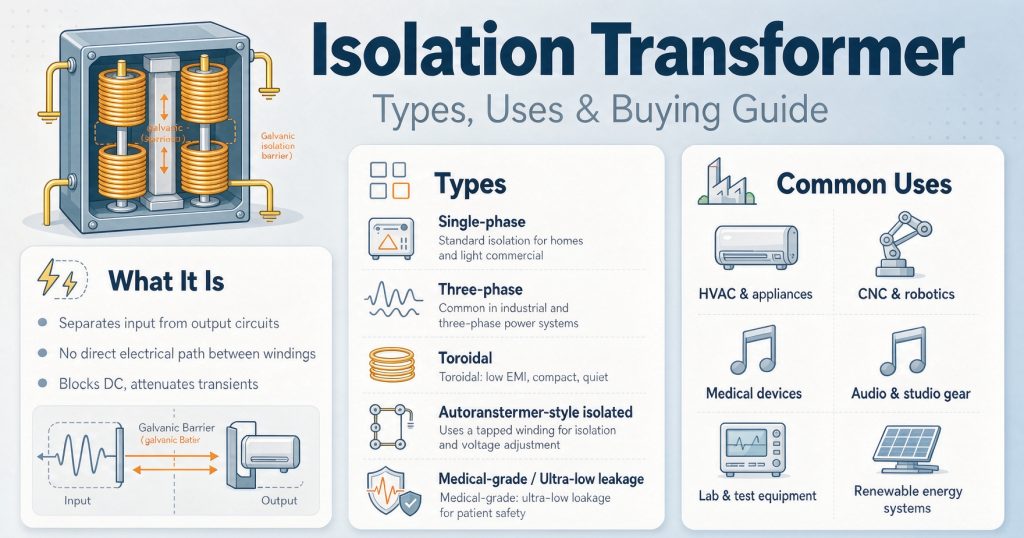
an isolation transformer is two windings that are magnetically coupled and electrically separate — no conductive path from input to output. That single property buys you four things (galvanic isolation, a new neutral reference, common-mode noise attenuation, and a separately derived system under NEC 250.30) and it does not buy you voltage regulation, surge protection, harmonic cancellation, or a smaller breaker.
Most buying guides stop there. This one goes further on the three things that actually change a purchase order: whether your unit is regulated by DOE at all (surprisingly, a lot of isolation transformers are excluded — and the test turns on the secondary voltage), how to size it so it doesn’t saturate on day one, and when you shouldn’t buy one at all.
Key numbers up front
| Item | Value | Where it comes from |
| DOE distribution transformer, output limit | ≤ 600 V | 10 CFR 431.192 |
| DOE capacity floor, dry-type | 15 kVA (liquid: 10 kVA) | 10 CFR 431.192 |
| Named exclusions from DOE scope | 13 categories | 10 CFR 431.192 |
| Three-phase kVA from amps | √3 × V_LL × I / 1000 | first principles |
| K-factor neutral bus, K-4 and above | ≥ 200% of full-load current | UL 1561 (via ABB technical paper) |
| Typical transformer magnetizing inrush | 8–12 × FLA for 100–500 ms | field rule of thumb; measure yours |
| Conversion, watts to BTU/hr | × 3.412 | first principles |
1. What an isolation transformer does — and four things it does not
Two windings, one core, no electrical connection between them. Energy crosses as a magnetic field. That’s it. Everything else follows from that.
What you genuinely get:
- Galvanic isolation. No DC path, no direct fault path from primary to secondary.
- A new neutral reference. A delta primary feeding a wye secondary with the neutral bonded creates a separately derived system per NEC 250.30 — critical when your supply is an ungrounded 480 V delta and your drives need a grounded 480Y/277 V.
- Common-mode noise attenuation, if (and only if) you specify an electrostatic shield. More on this in Part 6.
- Voltage conversion, if you want it. A 1:1 unit is pure isolation; a 480→208Y/120 unit does both jobs.
What you do not get, and this is where most specifications go wrong:
- Voltage regulation. A 1:1 isolation transformer passes through whatever the utility gives you, minus its own regulation. Sustained under-voltage still needs a stabilizer or an AVR.
- Surge protection. The windings attenuate fast transients somewhat. They are not an SPD. Pair the transformer with a surge protective device.
- Harmonic cancellation. A standard two-winding transformer does not remove harmonics. A K-rated unit survives the extra heat; it does not clean the waveform. Harmonic-mitigating transformers, phase-shifting and active filters do that — and they’re a separate line item.
- A smaller upstream breaker. Energizing a transformer pulls 8–12× full-load amps for the first few cycles. That usually makes the overcurrent device selection harder, not easier. See Part 5.
One more: the enclosure still has to be grounded. Isolation does not mean “no ground required.” The core and enclosure bond to the supply-side equipment grounding conductor so that a primary-to-core fault clears upstream.
If you’re new to the category, TransNine Electric‘s resource library has the background material on construction and standards, and the product index shows what’s actually available in isolation-duty designs.
2. Types: two ways to sort them
Competitor guides merge these. Keep them separate, because you specify them separately — construction goes in the electrical spec, application drives the options you pay for.
By construction
| Type | Insulation / cooling | Where it wins | Watch out for |
| Dry-type, VPI | Vacuum pressure impregnated polyester | General indoor, cost-sensitive | Lower moisture resistance than cast resin |
| Dry-type, cast resin | Epoxy encapsulated | Hospitals, tunnels, coastal, washdown | Heavier, higher first cost |
| Dry-type, sealed | Hermetically sealed | Dusty / corrosive atmospheres | Excluded from DOE scope as “sealed” (see Part 4) |
| Liquid-immersed | Mineral oil or ester | Outdoor, high kVA, utility | Oil containment, fire separation, maintenance |
| Toroidal | Ring core | Low stray field, audio / instrumentation | Usually small kVA only |
By job — this is the column that changes your spec
| Type | Built for | Defining option |
| General-purpose | Linear loads, voltage conversion | 1:1 or step ratio, shield optional |
| Shielded / ultra-isolation | Measurement, comms, imaging | Electrostatic shield, low inter-winding capacitance, dB spec |
| Drive isolation (DIT) | VFD and DC drive input | K-rating, 200% neutral, higher impedance, shield standard |
| K-factor rated | Non-linear load banks | K-4 / K-9 / K-13 / K-20 per UL 1561 |
| Medical | Patient-connected circuits | IEC 60601-1 insulation and leakage limits, LIM |
| Machine-tool (control) | Solenoids, contactors, relays | Integral overcurrent protection |
| Marine / shore | Corrosion, vessel grounding | Class society approval, IP rating |
3. Where they actually get used
| Application | What you’re solving | What you must specify |
| VFD / servo input | Ground reference, common-mode noise, source impedance | K-rating, delta-wye, shield, impedance |
| Data center PDU | Triplen heating in the neutral | K-13 minimum, K-20 for GPU clusters, 200% neutral |
| Hospital OR / ICU | Patient leakage, first-fault continuity | Medical grade, LIM, isolated power panel |
| Lab / metrology | Ground loops corrupting measurements | Ultra-isolation, dB and pF on the datasheet |
| CNC / machine tools | Control electronics vs. plant noise | Machine-tool or shielded general-purpose |
| Imported machinery | 400/380 V equipment on 480 V, or 480 V on 380 V | Step ratio + isolation + UL listing |
| Marine / offshore | Hull corrosion, shore-power isolation | Class approval, IP, anti-corrosion winding treatment |
Real installations differ from datasheets, so it’s worth looking at how these ratings land on site — the project case studies include harmonic-heavy and hospital environments.
4. The DOE question: is your isolation transformer even regulated?
This is the part every other guide skips, and it’s the part that can cost you a rejected shipment or a wasted compliance budget.
10 CFR 431.192 (eCFR current text) defines a distribution transformer with four positive conditions:
- Input line voltage ≤ 34.5 kV
- Output line voltage ≤ 600 V
- Rated for 60 Hz
- Capacity 10–5,000 kVA liquid-immersed, 15–5,000 kVA dry-type
…and then excludes thirteen categories. The ones that matter here:
- Autotransformer
- Drive (isolation) transformer
- Grounding transformer
- Machine-tool (control) transformer
- Nonventilated transformer
- Rectifier transformer
- Regulating transformer
- Sealed transformer
- Special-impedance transformer
- Testing transformer
- Transformer with tap range of 20% or more
- Uninterruptible power supply transformer
- Welding transformer
The four-part test nobody quotes
“Drive (isolation) transformer” is defined as a transformer that:
- Isolates an electric motor from the line;
- Accommodates the added loads of drive-created harmonics;
- Is designed to withstand the additional mechanical stresses resulting from an AC adjustable-frequency or DC motor drive; and
- Has a rated output voltage that is neither “208Y/120” nor “480Y/277”.
All four. It’s conjunctive. Miss one and you’re back in scope.
Two units, one difference
Take the same box twice: 75 kVA, dry-type, 480 V primary, 4.5% impedance, electrostatic shield, 60 Hz, feeding a drive.
| Unit A | Unit B | |
| Secondary | 208Y/120 V | 240 V delta |
| Drive-transformer test (4) | Output is 208Y/120 → condition fails | Output is neither → condition met |
| Special-impedance test | 75 kVA three-phase dry-type “normal” range is 1.0–5.0% → 4.5% is inside → not excluded | same |
| DOE result | In scope — efficiency applies; the 2029-04-23 standard applies to units manufactured or imported on/after that date | Excluded — DOE efficiency does not apply |
One line on the one-line diagram flips the regulatory answer. Nothing else changed.
Other quick boundaries:
- Below 15 kVA dry-type (10 kVA liquid) → not a distribution transformer. A 10 kVA control isolation transformer or a 5 kVA medical unit is outside DOE scope on capacity alone.
- Sealed or nonventilated construction → excluded by category.
- Tap range ≥ 20% → excluded.
Two cautions before you rely on any of this. First, DOE’s own rulemaking is not frozen: the 2029 standard has been the subject of active review, and a Congressional Review Act action at 90 FR 43371 (September 9, 2025) removed amendments to several sections of Part 431 that had taken effect December 23, 2024, reverting those sections to the December 22, 2024 version. Check the current eCFR text on the day you write the spec. Second, “excluded” means excluded from this energy standard — it does not mean exempt from UL, NEC, or your AHJ.
Voltage conversion and isolation are usually bought together; if your job is running 380 V machinery on US 480 V, the UL listed 480 V to 380 V transformer page covers that specific combination.
5. Sizing: three steps, not one rule of thumb
Every competitor says “add 20–25% headroom.” That’s not wrong, it’s just incomplete — it ignores harmonics and it ignores inrush. Do it in this order.
Step 1 — apparent power from measured current
kVA = √3 × V_LL × I / 1000
Worked: a servo drive drawing 6 A continuous, 12 A peak at 480 V three-phase.
- Continuous: √3 × 480 × 6 / 1000 = 4.99 kVA
- Peak (2–5 s): √3 × 480 × 12 / 1000 = 9.98 kVA
Step 2 — harmonic margin
Apply 1.25× for drive and other non-linear loads, per common practice for harmonic content. 4.99 × 1.25 = 6.24 kVA. Next standard catalog size: 7.5 kVA.
That 7.5 kVA unit also covers the 12 A peak — 9.98 kVA for a few seconds sits within the short-time overload capability most dry-types carry — so you don’t need to upsize again for the peak.
Step 3 — inrush, which nobody checks
7.5 kVA at 480 V three-phase: FLA = 7,500 / (√3 × 480) = 9.0 A.
Magnetizing inrush on energization runs roughly 8–12× FLA for 100–500 ms → 72–108 A, briefly. That’s the number your upstream breaker or fuse has to ride through without nuisance tripping. Verify the actual inrush on the specific design; it varies with core steel, residual flux and switching angle, and it is not a number to guess at.
The K-factor decision
If the load is non-linear, you need a K-rating, and you should know what it means. Per UL 1561, using the method of IEEE C57.110:
K = Σ (Ih/I1)² × h²
where h is the harmonic order and Ih/I1 is that harmonic’s current as a fraction of fundamental. Because of the h² term, high-order harmonics dominate. A purely linear load gives K = 1. UL recognizes K-1, K-4, K-9, K-13, K-20, K-30, K-40 and K-50.
Published selection guidance differs, and you should treat all of it as a starting point rather than a code minimum:
| Source A mapping | Source B mapping | ||
| K-4 | ≤ 35% non-linear | K-4 | ~50% non-linear |
| K-9 | 35–50% | K-9 | ~75% |
| K-13 | ≤ 75% | K-13 | ~100%, moderate spectrum |
| K-20 | up to 100% | K-20 | ~100%, heavy single-phase content |
The two don’t agree. That’s expected — K-factor is a thermal rating against a harmonic spectrum, not a percentage. If you have power-quality data, calculate it. If you don’t, measure before you buy, and round up.
K-rated construction is a different machine, not a derated one: subdivided or foil conductors, a core designed for higher-frequency reversal, an electrostatic shield as standard, and — critically — a neutral bus rated at approximately 200% of full-load current (Part 7). The dry-type transformer selection guide goes deeper on K-rating against harmonics. For GPU-dense or AI workloads the practical floor has moved to K-20; the hyperscale data centre K-factor project shows what that looks like built.
6. The shield: ask for numbers, not a checkbox
An electrostatic shield is a grounded conductive layer between windings. Its job is to shunt common-mode noise to ground instead of letting it couple across the inter-winding capacitance.
“Shielded” on a datasheet with no numbers is marketing. Ask for:
- Common-mode rejection, in dB, across a stated frequency range — no range, no comparison
- Inter-winding capacitance, in pF — lower is better for noise, but it interacts with the leakage-current limits in medical work
- Whether the shield is brought to a separate terminal — you want to land it on the supply-side ground reference, and you want the option to measure it
A shield is standard on drive isolation transformers and optional (i.e., extra cost) on general-purpose units. If noise is the reason you’re buying, it is not optional in practice.
7. The neutral: 200%, and you can’t reduce it
Triplen harmonics — the 3rd, 9th, 15th — are zero-sequence. On a four-wire wye system they are in phase across all three phases, so they add on the neutral instead of cancelling.
Two consequences:
- Rating. Per UL 1561, K-rated dry-type transformers require a neutral bus sized at approximately 200% of full-load current. Worked: a 75 kVA unit with a 208Y/120 V secondary has FLA = 75,000 / (√3 × 208) = 208 A; the neutral bus must be rated about 416 A. Recompute from your own nameplate rather than copying a catalog example — published figures sometimes mix single-phase and three-phase math.
- Code. NEC 220.61(C)(2) prohibits applying the normal neutral demand reduction to that portion of the load consisting of non-linear loads on a 3-phase, 4-wire wye system. The neutral has to be sized for the current that will actually be there — which under heavy single-phase non-linear load can exceed the phase current.
Also bond the secondary neutral at exactly one point per separately derived system, per NEC 250.30.
8. Enclosure and environment
| Environment | Typical enclosure | Notes |
| Clean indoor electrical room | NEMA 1 / IP20 | Ventilation and clearance still required |
| Industrial, dust | NEMA 12 | Gasketed, no knockouts on top |
| Outdoor | NEMA 3R | Rain and sleet; not dust-tight |
| Washdown / food / chemical | NEMA 4X | Stainless or non-metallic |
| Coastal / marine | IP44 or better + anti-corrosion winding treatment | Verify class society requirements |
For exposed or corrosive sites, marine transformers are built to that duty; outdoor enclosed cast resin units are the other common route, and both are stocked in several NEMA and IP configurations.
Two deratings buyers forget:
- Altitude. Above 1,000 m, air gets thinner and cooling drops. Plan on roughly 1% capacity reduction per 100 m of additional altitude.
- Ambient. Standard ratings assume a 40 °C ambient. A 50 °C electrical room is not a 40 °C electrical room.
9. Medical-grade: stricter, and not interchangeable
⚠️ This section is orientation, not a compliance determination. Limits depend on the applied-part classification, the edition of the standard your market enforces, and the measurement network used. Confirm every number with your compliance engineer and the applicable edition before you release a PO.
The framework in IEC 60601-1 distinguishes:
- MOOP (Means of Operator Protection) — commonly cited as ≥ 1,500 VAC isolation
- 2×MOPP (Means of Patient Protection) — commonly cited as ≥ 4,000 VAC for patient-contact circuits
Commonly cited patient leakage limits, by applied part:
| Applied part | Normal condition | Single fault |
| BF | ≤ 100 µA | ≤ 500 µA |
| CF | ≤ 10 µA | ≤ 50 µA |
Note the gap: industrial units with a 4 kV Hi-Pot routinely show chassis leakage in the milliamp range — one to two orders of magnitude above the medical limit. A general-purpose isolation transformer is not a medical isolation transformer, and substituting one will fail incoming inspection.
Healthcare isolated power systems also need a line isolation monitor on the secondary to alarm on a first fault. Confirm the alarm threshold against the applicable code edition.
Sources disagree on earth-leakage limits — figures ranging from 300 µA to 500 µA normal condition appear in circulation, depending on edition and measurement method. Do not pick one from a blog post.
10. When you shouldn’t buy one
This is the section no vendor writes.
VFDs usually don’t need an isolation transformer. In most installations a 3% or 5% line reactor provides equivalent source impedance for transient and harmonic mitigation, at a fraction of the cost and footprint. Specify a drive isolation transformer when you actually need one of its unique properties.
The clearest case is grounding. Per the NEMA Application Guide for AC Adjustable Speed Drive Systems (as commonly cited): a ground common with electrical welding equipment, or with large-current equipment rated more than 5× the drive’s full-load current, should not be used — and where either condition exists, use an isolation transformer sized for the installed control, with a wye secondary neutral solidly grounded. That’s a real requirement, not a preference.
The other honest “don’t buy” cases:
- You only need voltage matching and no isolation is required → an autotransformer is smaller and cheaper. Just never substitute one where isolation is the point.
- Your problem is sustained over/under-voltage → you need regulation, not isolation.
- Your problem is harmonics at the point of common coupling → a K-rated transformer survives the heat; it doesn’t reduce distortion. You need a filter or a harmonic-mitigating transformer.
- Your problem is dv/dt at the motor terminals causing bearing damage → that’s an output-side problem. Isolation on the input does nothing for it.
11. What it costs
Every other guide on this keyword quotes zero prices, which is remarkable for a buying guide. Here is what can be said honestly.
Small units, where catalogs exist. One US industrial distributor published 2026 ranges of roughly 400–800** for a general-purpose isolation transformer in the 5–7.5 kVA band and **800–1,500 for a drive isolation transformer at the same size — the premium buying you the K-rating, the shield as standard, and the 200% neutral. Treat that as a single-source snapshot, not a benchmark.
Above roughly 75 kVA, catalog pricing stops meaning anything. The unit becomes project-specific: copper versus aluminium, impedance, enclosure, loss guarantees and lead time all move the number, and two suppliers quoting the same kVA can differ by a multiple, not a percentage.
Use a cost-driver table instead of a price table. These are the options that move the quote, roughly in order of impact:
| Option | Effect on price | When it’s worth it |
| Copper instead of aluminium windings | Materially higher | Long running hours, high load factor, tight space |
| K-rating (K-13 / K-20) | Higher — bigger core and more conductor | Non-linear load above roughly a third of the bank |
| Electrostatic shield | Moderate adder | Any noise-driven purchase |
| 200% neutral | Included with K-rating; adder otherwise | Standard on 4-wire wye with electronics |
| Low-loss / amorphous core | Higher first cost | High load factor, long ownership horizon |
| Cast resin over VPI | Higher | Coastal, washdown, hospital, tunnel |
| NEMA 3R / 4X / 12 enclosure | Moderate | Environment-driven, not optional |
| Third-party listing (UL / CSA) | Moderate | Usually a prerequisite, not an option |
A sanity check you can run on any quote: divide price by kVA and compare across your three bids. If one is less than half the others, the difference is almost always winding material, K-rating, or a missing shield — not efficiency of manufacture. Ask which, in writing.
And the thing price tables never show: at 75 kVA and above, the no-load loss you buy is a 24/7 expense for the next 20-plus years. A unit that costs $800 more and loses 200 W less pays that back in well under three years at typical US commercial rates. Get the loss figures before you compare the prices.
12. The heat has to go somewhere
Isolation transformer losses become heat, and in an indoor electrical room that’s an HVAC load, not a rounding error.
Conversion: watts × 3.412 = BTU/hr.
Worked: a 75 kVA unit at 97.5% full-load efficiency dissipates 75,000 × 0.025 = 1,875 W → 6,398 BTU/hr. With 12,000 BTU/hr per ton of cooling, that’s a bit over half a ton you have to remove — and that’s before adding the no-load loss, which is there 24/7 whether or not anything is plugged in.
Get both loss numbers from the supplier and give them to the mechanical engineer. Transformers in unventilated rooms are one of the most common causes of premature insulation failure.
13. What to put in the RFQ
Eighteen fields. If a quote is missing more than two of them, you don’t have a quote — you have an advertisement.
| # | Field | Notes |
| 1 | kVA | State continuous, and peak with duration |
| 2 | Primary voltage + taps | Include tap range — ≥20% changes DOE status |
| 3 | Secondary voltage + phasor | e.g. 208Y/120, 240D — this drives the DOE test |
| 4 | Phase and frequency | 60 Hz assumed in US |
| 5 | Winding material | Copper or aluminium — say which |
| 6 | Impedance, % | Also determines special-impedance status |
| 7 | K-factor | Or state “K-1, linear load only” |
| 8 | Neutral rating | 200% minimum for K-rated |
| 9 | Electrostatic shield | Yes/no + dB and pF |
| 10 | Insulation class and temp rise | e.g. 220 °C system, 115 K rise |
| 11 | BIL | If medium-voltage primary |
| 12 | Enclosure | NEMA or IP |
| 13 | Cooling | AN / AF, ONAN |
| 14 | Altitude and ambient | Derating basis |
| 15 | Applicable standards | UL 1561 / UL 1562 / CSA C22.2 No. 47 / IEC 61558 |
| 16 | Sealed or ventilated | Affects DOE exclusion |
| 17 | No-load and load losses, in watts | Needed for heat load and TCO |
| 18 | Tests required | Routine per-unit, plus type tests |
14. Tests and acceptance
Ask for these on your unit’s serial number, not as generic type-test certificates:
- Winding resistance, all taps
- Turns ratio and polarity / vector group
- Insulation resistance
- Applied potential (Hi-Pot) — production test, per unit
- Induced potential test
- No-load loss and no-load current, at rated voltage
- Load loss and impedance, at rated current
- Temperature rise, if a type test is due on this design
- Partial discharge, for cast resin MV units
- Shield continuity and, if specified, measured inter-winding capacitance
At delivery: check nameplate against the approved drawing, verify the shield terminal is present and landed, confirm neutral bus rating, and megger before energizing. Photograph the nameplate — it’s the fastest way to settle a warranty question three years later.
15. Five mistakes that show up on site
None of these are exotic. All five appear on installed equipment regularly.
1. Bonding the shield at both ends. The shield is a Faraday cage against capacitive coupling. Land it at one point, on the supply-side ground reference. Bond both ends and you have built a ground loop with a conductor running straight through the middle of your transformer — which is the thing you bought the transformer to avoid.
2. Tying the secondary neutral to the supply earth. This defeats the isolation you paid for. Unless your application calls for it, the secondary is a separately derived system and gets bonded once, at the transformer, per NEC 250.30. Marine applications are the usual exception, where the secondary neutral may need to land on the vessel’s grounding bus.
3. Specifying K-1 for a room full of switch-mode supplies. The unit will carry the load and then cook. Industry commentary puts the failure window on that mistake at roughly two to four years against a twenty-year design life. If more than about a third of the load is electronic, K-1 is the wrong answer.
4. Sizing to running load instead of drive input current. A transformer matched exactly to running current has no margin for the harmonic content and no margin for inrush. It saturates on the first cycle and the upstream device sees it.
5. Reading “isolated” as “safe to leave floating.” An ungrounded secondary survives a first ground fault without tripping — which is the point in a hospital — but it also means nobody knows a fault exists. That is exactly why a line isolation monitor is required there. Ungrounded without monitoring is a hazard, not a feature.