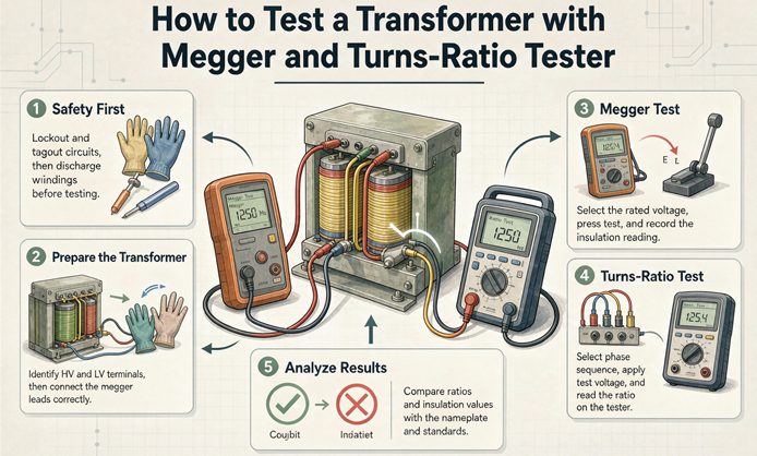
Two instruments, two questions. A Megger pushes DC through the insulation and reads megohms, and you pass it at roughly 1 megohm per kV of winding rating. A turns-ratio tester puts low AC on the HV winding and compares induced LV volts to the nameplate, and you pass that at 0.5 percent. Megger first, ratio second.
Those two sentences are the whole job. Everything else on this page is about the four ways the numbers lie to you after you have taken them: temperature, tap position, vector group, and the voltage base you typed into the instrument. Get those four right and a transformer test takes about an hour. Get them wrong and you will condemn a healthy unit, or worse, energize a wet one because the ratio test looked perfect.
One note on the word. Megger is a brand, from Megger Ltd in Dover, England, and it turned into the generic verb the way Kleenex did. If your instrument says Fluke, Hioki, AEMC or Megger on the case, it is the same test: apply DC, measure the leakage current, display resistance in megohms. We will use the word the way the trade uses it.
What each instrument can and cannot see
The reason people get confused here is that both instruments hand you one number that looks like a grade. Neither one is a grade. They answer different questions, and a pass on one says nothing about the other.
| Instrument | The question it answers | What it actually finds | What it cannot see |
|---|---|---|---|
| Megger, 60 second spot reading | Is this safe to energize | Moisture in the paper, surface contamination, cracked bushing, tracking, a winding grounded through a fault | A shorted turn, a wrong tap, a reversed winding, core looseness |
| Megger, 10 minute / PI | Is the moisture inside the insulation or on the surface | Absorbed moisture, thermal aging of the paper | Anything electrical, and it says little on cast resin |
| Turns-ratio tester | Will the voltage come out right | Wrong tap, reversed polarity, wrong vector group, a whole section shorted, an open winding, a mis-wired terminal | One shorted turn in a large winding, moisture, winding deformation that preserves the ratio |
| Winding resistance (third instrument, not covered here) | Are the connections tight | Loose lug, burnt tap contact, broken strand, cold solder joint | Insulation condition of any kind |
Read the third column and you can see why the order matters. The Megger is a safety gate. The ratio test is an accuracy gate. You do not want to spend forty minutes proving the voltage will be right on a unit you should not energize at all.
There is a second reason for the order that shows up in the field. A transformer with a winding-to-winding short will often return a turns ratio that looks fine, because the ratio only cares about the turns that are still in circuit. The Megger catches that same fault immediately. So the cheap test catches the expensive fault, and the expensive test catches the cheap fault. Run the cheap one first.
If you want the factory side of this picture, meaning the tests a unit passes before it ships, that is a different document and it is here: transformer routine testing, what every unit should pass. This page is the field version, two portable instruments, on a unit that is already installed or just landed on the dock.
Before you touch a lead
Nothing below works if the unit is still connected to something that can backfeed it. OSHA 1910.333(b) requires a lockout and tagout procedure for this work in the United States, and NFPA 70E sets the arc flash boundary and the PPE category for the task. If you are outside the US, your local electrical safety regulation will have an equivalent. The procedures are similar enough that the five steps below travel well.
- Find every source, not just the obvious one. The breaker you opened is one. A delta tertiary, a tie to an adjacent lineup, a generator, a UPS output, a capacitor bank, a voltage transformer backfeeding through a control circuit, and a portable generator somebody plugged in last week are the others. On a two-source lineup, the second source is the one that hurts you.
- Prove the tester, then test for dead, then prove the tester again. Test on a known live source, test the conductor, test the known live source a second time. A meter with a blown fuse reads zero volts on everything, and that is the failure mode that kills people.
- Ground both sides. Apply portable grounds to the HV terminals and the LV terminals, or close the grounding switches. Ground before you handle a bolted connection, not after.
- Disconnect everything that is not the transformer. This step decides whether the numbers mean anything.
- Write down the temperature before you start. Winding temperature if you can get it, oil temperature if you cannot. Every insulation number later in this page depends on this one line.
Step four deserves its own paragraph, because it is where most bad readings come from.
If the surge arresters are still bolted to the bushings, a 5 kV Megger is testing the arrester in parallel with the winding, and the reading is meaningless. If the cable terminations are still made up, you are testing the cable too, and a wet cable will condemn a dry transformer. If the neutral is still bonded to ground, the HV to LV test reads close to zero and somebody writes “winding shorted” on a unit that is perfectly fine.
So open the arresters, lift the cable lugs, remove the neutral bond, and discharge the winding through a resistor before you clip anything on. Then confirm zero volts with the meter you proved in step two. A 1,000 kVA unit at 13.8 kV can hold a nasty charge for several minutes after the source opens.
For a 480 V dry type in a mechanical room, the list is shorter but the same shape: open the feeder, lock it, verify dead, lift the neutral bond, and disconnect any downstream VFD so you are not megging through the drive’s DC bus.
The Megger test, connection by connection
A Megger applies a regulated DC voltage between two points and measures the tiny current that leaks through the insulation. Resistance is volts divided by current, so a good insulation returns a large number and a wet one returns a small number. That is the entire principle. The craft is in choosing the voltage, choosing the points, and knowing what the number is supposed to be at the temperature you are standing in.
Pick the test voltage, and stop there
The voltage has to be high enough to stress the insulation in a way that reveals weakness, and low enough that it does not damage anything. The table below is the field convention most North American crews use, and it lines up with the ranges published in IEEE C57.152 and in NETA’s acceptance testing standard.
| Winding rated voltage | DC test voltage | Minimum duration | Typical unit |
|---|---|---|---|
| 600 V and below | 500 V | 60 s | 480 V dry type, 480 delta to 208Y/120 |
| 601 V to 2,500 V | 1,000 V | 60 s | 2,400 V and 2,400/4,160 V class |
| 2,501 V to 5,000 V | 2,500 V | 60 s | 4,160 V class |
| Above 5,000 V | 5,000 V | 60 s | 13.8 kV, 25 kV, 34.5 kV class |
The classic rule of thumb is rated winding voltage plus 1,000 volts, capped by whatever your instrument can produce. For a 13.8 kV winding that rule asks for 14.8 kV and your instrument tops out at 5 kV, so 5,000 volts it is. The rule is a ceiling, not a target. Do not go looking for a 15 kV megger to satisfy it, and never exceed the low frequency withstand of the winding you are testing.
One warning that costs real money. A higher test voltage is not a better test. On a winding that is already wet, 5 kV instead of 500 V can track across a contaminated bushing surface and turn a dry-out job into a rewind. If you suspect moisture, test at the low end of the range first.
The five connections that cover a two winding unit
Clip the red lead where the table says, clip the black lead to ground, and leave the guard terminal alone until you need it. Every reading is taken at the same test voltage for 60 seconds.
| Test | Red lead to | Black lead to | What a low reading means |
|---|---|---|---|
| HV to ground | H1, H2, H3 all jumpered | Tank and core, LV grounded | HV insulation to ground is compromised, or the bushing is dirty |
| LV to ground | X1, X2, X3 all jumpered | Tank and core, HV grounded | LV insulation to ground, often a cable or a wet termination |
| HV to LV | HV terminals | LV terminals, tank grounded | Inter-winding insulation, the fault that turns a transformer into a fire |
| Core to ground | Core clamping frame or a core bolt | Tank | Circulating current in the core, a shorted core bolt, or a damaged lamination |
| Frame to tank | Lifting frame or an internal support | Tank | Insulation between internal structures, mostly on larger units |
Three of those five are the ones you will take on a routine basis. The last two need the tank open or a core access point, so they belong to commissioning and to any unit that has been opened for repair.
For a three winding unit with a tertiary, add HV to tertiary, LV to tertiary, and all three windings jumpered to ground. Every winding gets a turn as the red lead and a turn as part of the grounded group. That is the only way to be sure which pair is weak.
Guard, and why your reading was jumping
The guard terminal exists to swallow surface leakage current so it does not show up as a false low reading. At 5 kV, a damp porcelain surface across a 200 mm creepage path can conduct more current than the insulation you are trying to measure, and the result is a reading that bounces around and then settles low. Clip the guard lead to a bare conductive band around the bushing below the top shed. The surface current goes to guard, the through-insulation current goes to the meter, and the number stops moving.
If you do not have a guard terminal, clean and dry the bushings with a lint free cloth and re-test. That is the whole fix in nine cases out of ten.
What a good number looks like
The widely used field floor is 1 megohm per 1,000 volts of winding rating, measured at 1 minute. A 13.8 kV winding passes the floor at 13.8 megohms. A 480 V winding passes at 0.48 megohms, which is a number so low that any real transformer will clear it by three orders of magnitude, so for LV units the floor is not the useful test.
That is the honest limitation of the rule, and it is where most online guides stop. The floor tells you the unit is not soaking wet. It does not tell you the unit is healthy, and it does not tell you the unit is the same as it was last year.
Three things are more informative than the floor:
- Phase to phase comparison. On a three phase unit, the three phases should sit within a factor of two of each other, and on a healthy unit they are usually within 20 percent. One phase at half the other two is worth an hour of investigation even when all three clear the floor.
- Trend against the last reading at the same temperature. A unit that read 6,000 megohms at 20 °C for a decade and now reads 2,500 at 20 °C has lost more than half its insulation resistance. IEEE C57.152 treats a drop of that size as a trigger for investigation regardless of whether the absolute number still clears the floor.
- Shape of the curve during the 60 seconds. A reading that climbs steadily and is still climbing at 60 seconds is normal absorption current, and it is a good sign. A reading that sags after an initial peak is a warning. A reading that sits flat and low from the first second is a fault.
Temperature is the biggest lie in the record
Insulation resistance falls as temperature rises, roughly by half for every 10 °C. That single sentence explains most of the “my transformer is failing” emails that arrive every autumn.
The correction is:
IR at 20 C  =  IR measured  x  2^((t - 20) / 10)

t = winding temperature during the test, in C
Which gives you this multiplier table. Multiply the reading you took by the factor and you have the number that belongs in the 20 °C column of your record.
| Winding temp during the test | Multiply the reading by |
|---|---|
| 10 °C | 0.50 |
| 15 °C | 0.71 |
| 20 °C | 1.00 |
| 25 °C | 1.41 |
| 30 °C | 2.00 |
| 35 °C | 2.83 |
| 40 °C | 4.00 |
| 45 °C | 5.66 |
| 50 °C | 8.00 |
| 60 °C | 16.0 |
Now the arithmetic that matters. A 1,000 kVA unit read 1,500 megohms at 20 °C at its last test. This year you get 320 megohms at 40 °C. Taken at face value that is a 79 percent drop and a unit headed for a rewind.
Corrected: 320 × 4.00 = 1,280 megohms at 20 °C. That is 15 percent below last year, which is ordinary aging on a 20 year old unit. The correct call is pass, watch it, and test again next year at the same temperature.
Run the same mistake in the other direction and you get a false pass, which is the more dangerous of the two. A unit tested in January at 15 °C reads 1,050 megohms against a 1,490 megohm baseline taken at 20 °C. That looks like a 30 percent drop on a 25 year old unit, which is the kind of line most crews write down and walk away from. Corrected, 1,050 × 0.71 = 743 megohms at 20 °C, which is a 50 percent loss and a unit that needs attention this year rather than next. Cold weather flatters a wet winding. It is also why two crews can test the same transformer in the same month and report numbers five times apart.
Two practical notes before you trust any of this. First, the halving rule is a rule of thumb for oil paper insulation, and the exact correction your manufacturer publishes will differ. Use the rule to catch a wrong conclusion, not to certify a unit. Second, the temperature you need is the winding temperature, not the ambient, and not the oil temperature taken five minutes after shutdown. A large unit takes two to four hours to equalize after it comes off load. If you test a hot unit, you are not measuring insulation, you are measuring how recently it ran.
PI and DAR, and the case where they do not apply
A spot reading at 60 seconds tells you how much leakage there is. It does not tell you whether the moisture is on the surface or inside the paper. That is what the absorption ratios are for.
- Polarization Index, PI = reading at 10 minutes ÷ reading at 1 minute.
- Dielectric Absorption Ratio, DAR = reading at 60 seconds ÷ reading at 30 seconds.
| PI | Reading | What it usually means |
|---|---|---|
| Above 2.0 | Dry and healthy | Normal for oil paper in good condition |
| 1.5 to 2.0 | Marginal | Some moisture or thermal aging, trend it |
| 1.1 to 1.5 | Wet or contaminated | Dry out before energizing, or investigate |
| Below 1.1 | Very wet, or a fault | Do not energize |
DAR above 1.4 is healthy, 1.25 to 1.4 is questionable, below 1.25 is wet. DAR takes 60 seconds instead of 10 minutes and catches the same moisture in most cases, which is why crews use it on units where a 10 minute test is awkward.
Here is the part almost nobody writes down. PI was built for oil paper, and on cast resin dry type transformers it does not carry the same meaning. A cast resin winding absorbs very little moisture, so the absorption current that PI is designed to measure barely exists. A PI of 1.1 to 1.3 on a healthy cast resin unit is normal and is not a fail. If you apply the oil paper thresholds blindly, you will condemn every dry type in the building. Judge cast resin on the spot reading, on phase comparison, and on the trend, and use PI only for oil immersed units or for resin units where you have a documented history of that specific design.
One more trap. PI needs a stable temperature for the full ten minutes. If the unit is cooling while you test, the resistance climbs for a reason that has nothing to do with moisture, and PI reads artificially high. Test a unit at rest, not one that has been off load for ten minutes.
The turns-ratio test
A turns-ratio tester applies a low AC voltage to the HV winding, measures the induced voltage on the LV winding, and divides. Because the two voltages are proportional to the turns, the voltage ratio is the turns ratio. Instruments in the field use anywhere from a couple of volts to a few hundred volts on the primary, which is why the test is safe on a unit you have just megged, and why the answer is accurate to a few hundredths of a percent on a modern digital unit.
The nameplate tells you what the ratio should be. That sentence contains three traps, and all three produce a “failed” unit. Before you clip anything on, find the ratio, the tap position that ratio applies to, and the vector group on the plate itself rather than on the submittal, because the two disagree more often than anyone expects. The field by field reading of that plate is here if you need it: how to read a transformer nameplate.
Trap one: the tap position
The ratio printed on a nameplate is quoted at one specific tap, usually the principal or rated tap. On a five position tap changer with plus and minus 2.5 percent steps, that is usually the middle position, tap 3. If you test at tap 4 and compare against the tap 3 nameplate, you will measure a 2.5 percent deviation.
Now hold that against the pass line. IEEE C57.12.90 and IEC 60076-1 both put the acceptance limit at plus or minus 0.5 percent of the rated ratio. One tap step is 2.5 percent. One tap step is five times the entire pass band. It is the single most common false failure in the trade, and it is fixed by writing the tap position on the test sheet before you clip the leads on.
For a 13,800 to 480 V unit with a plus and minus 2 times 2.5 percent tap changer, here is what every position should read. Line ratio in the middle column, winding ratio in the right, and the difference between those two columns is trap number two.
| Tap | HV volts | Line ratio (V_HV ÷ V_LV) | Winding ratio (Dyn11) |
|---|---|---|---|
| 1 (+5%) | 14,490 | 30.19 | 52.29 |
| 2 (+2.5%) | 14,145 | 29.47 | 51.04 |
| 3 (rated) | 13,800 | 28.75 | 49.80 |
| 4 (−2.5%) | 13,455 | 28.03 | 48.55 |
| 5 (−5%) | 13,110 | 27.31 | 47.31 |
Note what a 2.5 percent ratio error does at the output. Two and a half percent of 480 volts is 12 volts. A unit stuck one tap off delivers 468 or 492 volts to a panel full of equipment expecting 480, and nothing in the building will tell you why the contactors are chattering.
Trap two: the square root of three
This is the one that gets good units rejected, and no page on the first search result explains it.
The nameplate ratio is a line to line ratio. A turns-ratio tester in single phase mode measures a winding ratio, because it puts voltage across one HV winding and reads one LV winding. On a wye connected winding the winding voltage is the line voltage divided by 1.732. On a delta connected winding the winding voltage equals the line voltage. So the two ratios differ whenever the two sides have different connections.
The rule is one line:
Winding ratio = Line ratio x (1.732 if LV is wye and HV is delta)
Winding ratio = Line ratio x (0.577 if LV is delta and HV is wye)
Winding ratio = Line ratio (same connection both sides)| Vector group | HV connection | LV connection | Multiplier | 13,800/480 ratio the tester shows |
|---|---|---|---|---|
| Dyn11 | Delta | Wye | 1.732 | 49.80 |
| Yyn0 | Wye | Wye | 1.000 | 28.75 |
| Dd0 | Delta | Delta | 1.000 | 28.75 |
| Yd1 | Wye | Delta | 0.577 | 16.60 |
So a technician testing a 13,800 to 480 V Dyn11 unit in single phase mode reads 49.80, compares it to the 28.75 on the nameplate, computes a 73 percent error, and writes up a failed transformer. The transformer is perfect. The comparison was wrong.
Modern three phase testers ask you for the vector group and do this conversion internally, which is why the same unit reads 28.75 on one instrument and 49.80 on another. Neither instrument is broken. This is worth saying out loud to whoever reads the report.
Which gives you two diagnostic short cuts worth memorizing:
- A deviation of about plus 73 percent, or about minus 42 percent, on all three phases is the square root of three. Check the vector group setting before you check the winding.
- A deviation of about 2.5 percent, or any clean multiple of it, is a tap position. Check the tap before you check the winding.
Neither of those is a fault. Both get written up as one every week somewhere.
Trap three: the voltage base you typed in
If all three phases are off by the same small percentage, in the same direction, and the number is not 2.5 or 73, look at what you entered as the rated voltage.
Enter 13.2 kV for a 13.8 kV unit and every reading comes back 4.5 percent high, because 13.8 ÷ 13.2 = 1.045. Enter 460 volts for a 480 volt secondary and you get 4.3 percent, near enough to the same signature that you should check the base before you check anything else. Enter 12,470 for a 13,800 unit and you get 10.7 percent, which is 21 times the pass band and looks like a catastrophe.
Three phases, same error, same sign, no single phase worse than the others: that pattern is an input error, not a winding fault. A real winding fault is almost never symmetric.
What 0.5 percent means in turns, and why the ratio test is not a shorted turn detector
Everybody on the first page of Google says the turns-ratio test detects shorted turns. It does, in a limited way, and it is worth doing the arithmetic before you rely on it.
The pass band is 0.5 percent of the ratio, which means 0.5 percent of the HV turns. Take a 13.8 kV winding designed at roughly 5 volts per turn, which puts it somewhere near 2,760 turns. Half a percent of 2,760 is about 14 turns.
So the ratio test sees a defect of roughly 14 turns on that winding. One shorted turn changes the ratio by 1 ÷ 2,760, which is 0.036 percent, or seven percent of the pass band. It is invisible, and it stays invisible until enough turns are shorted to cross the line. Meanwhile those few shorted turns are circulating a large current and cooking the paper around them, which is exactly the failure mode you were trying to catch.
This is not an argument against the test. It is an argument about what to expect from it. The ratio test reliably finds a whole section shorted, a winding connected backwards, a tap changer that did not land, a phase swapped at the terminal block, and a unit built to the wrong ratio. Those are all real and expensive. For the single shorted turn, the instruments that see it are dissolved gas analysis on an oil unit, sweep frequency response for deformation, and excitation current for core and winding faults. If your only field instrument is a TTR, you are screening for the big stuff and you should say so in the report.
Run every tap, and never crank an OLTC by hand
IEEE C57.12.90 requires the ratio to be verified at all tap positions, not just the rated one. On a five position unit that is fifteen measurements, three phases across five taps, and a modern three phase tester does it in a few minutes while the same job with a single phase instrument takes most of an hour. Take the fifteen readings. The tap changer is a mechanical device with contacts that erode, and a ratio that is correct at tap 3 and off by 1 percent at tap 5 is telling you the changer is not landing cleanly.
If the unit has an on-load tap changer, use the tester’s remote control to step it and never operate the mechanism by hand with test voltage applied. Stepping a loaded tap changer under test voltage arcs the contacts and can weld them.
One more connection detail for delta HV windings. In single phase excitation across H1 and H2 on a delta winding, the third leg is also in the circuit, and the measured ratio is not the winding ratio unless you use the three phase equivalency method. The US Bureau of Reclamation field guide is explicit about this for delta-wye and wye-delta units, and it is worth the read if you test those regularly: FIST 3-31, Transformer Diagnostics. A three phase tester handles this automatically; a single phase instrument does not, and that is another source of phantom failures on delta units.
What the hour actually looks like
Time budgets are the part of a test procedure nobody publishes, and they are the part that decides whether the job gets done at all. Here is one we would defend for a three phase unit with a five position tap changer.
| Step | Time | What makes it longer |
|---|---|---|
| Isolate, lock out, prove dead, ground | 15 min | A second source on the lineup, or a shared switchgear room |
| Open arresters, lift cable lugs, remove neutral bond | 10 min | Bolted terminations in a tight compartment |
| Read and record winding temperature | 2 min | Getting a real winding temperature instead of an ambient guess |
| Insulation resistance, five connections at 60 s | 12 min | Lead dressing at 5 kV, and a guard lead on dirty bushings |
| Polarization index on HV to ground | 10 min | Nothing, it is ten minutes of waiting. Skip it on cast resin |
| Turns ratio, three phases across five taps | 10 min | A single phase instrument takes 45 to 60 minutes for the same fifteen readings |
| Correct for temperature, compare, write it up | 10 min | This is the step that gets skipped, and it is the one that matters |
Add it up and a competent crew is looking at roughly 70 minutes, most of which is spent climbing, isolating, and writing rather than testing. Compare that against the alternative, which is finding the problem at energization with a crane on site and a project schedule slipping, and the arithmetic stops being close.
The decision tree
Here is the sequence we would put on a laminated card. It runs the cheap test first, and it stops at the first hard stop.
| Step | Test | Result | Action |
|---|---|---|---|
| 1 | IR, HV to ground | Below the floor after temperature correction | Stop. Do not energize. Dry out and retest. |
| 2 | IR, all pairs | Passes floor, but one phase below half the others | Investigate that phase. Check bushing, cable, and termination first. |
| 3 | IR, HV to LV | Near zero | The neutral bond is still in place, or there is a real inter-winding fault. Check the bond before condemning. |
| 4 | PI, oil immersed | Below 1.5 with a passing spot reading | Moisture is present. Plan a dry-out, keep it energized only if the load allows. |
| 5 | TTR, all phases | Off by about 73 percent or 42 percent | Vector group setting. Fix the instrument, not the transformer. |
| 6 | TTR, all phases | Off by about 2.5 percent or a multiple | Tap position. Confirm the physical tap and the nameplate tap. |
| 7 | TTR, all phases | Off by 4 to 11 percent, same sign | Wrong voltage base entered in the instrument. |
| 8 | TTR, one phase | Off by 0.5 to 1 percent, other two clean | Real suspect. Follow with winding resistance on that phase. |
| 9 | TTR, all pass, one tap | Off by more than 1 percent at one position only | Tap changer contact. Exercise it and retest. |
| 10 | Everything passes | Inside 0.5 percent on every tap, IR above the floor | Energize, record, compare in 12 months. |
Steps 5, 6 and 7 account for most of the “failed” transformers that come back to a manufacturer, and all three are operator errors rather than products.
Six results that look like failures and are not
- The ratio is 73 percent high. Delta primary, wye secondary, single phase tester, no vector group entered. The winding ratio is 1.732 times the nameplate line ratio. Nothing is wrong.
- The ratio is 2.5 percent off. One tap step. Check the physical pointer against the nameplate before you check anything else.
- Every phase is about 4.5 percent off in the same direction. Someone entered 13.2 kV for a 13.8 kV unit, or 460 volts for a 480 volt unit.
- Insulation resistance fell by three quarters overnight. The winding was at 40 °C instead of 20 °C. Correct it and the drop is 15 percent.
- HV to LV reads close to zero on a unit that just passed HV to ground. The neutral is still bonded. Lift it and retest.
- PI is 1.2 on a cast resin unit. Normal for the material. Cast resin does not absorb enough moisture for the absorption current to develop.
And a seventh that is not a failure but is not a pass either. The 60 second reading is still climbing when the timer stops. That is absorption current on a large winding and it is completely normal. It is also the reason to run the 10 minute test rather than argue about the number.
What to record, so next year means something
A test without a temperature is a number without a unit. Ten minutes of writing turns it into a record you can compare against.
| Field | Why it matters |
|---|---|
| Date and time | Aging trends need an interval, not a date |
| Ambient and winding temperature | Every IR number is meaningless without it |
| Test voltage used | 500 V and 5,000 V on the same winding give different numbers |
| 60 second reading, each pair | The spot value every standard references |
| 10 minute reading and PI | Separates surface moisture from absorbed moisture |
| Ratio at every tap, every phase | Fifteen lines that catch a bad tap changer contact |
| Vector group and tap position | The two settings that produce most false failures |
| Instrument model and serial | If two crews disagree, this is the first thing to check |
| Who performed the test | A record without a name is a rumor |
Keep the record with the unit, in the same folder as the factory test report. When the field number disagrees with the factory number, the factory report wins on ratio and the field record wins on insulation, because the factory tested at 20 °C in a controlled room and your field test did not.
If you are comparing across units and want the standard side of the argument, this is a useful reference to have open: IEC 60076 vs ANSI/IEEE standards for export transformers. Both families put the ratio limit at 0.5 percent, and they differ in how they apply it to three phase units, which matters when a European inspector and a North American inspector look at the same fifteen readings.
When these two tests are not enough
Being clear about the limits is more useful than another paragraph about the procedure.
- A ratio change with clean insulation points to winding deformation after a through fault. Neither of these instruments will size it. Sweep frequency response will.
- A hot spot found in dissolved gas analysis will not show up in a ratio, because the turns are still electrically intact. You need DGA and thermography.
- Bushing condition needs a power factor or tan delta test at 10 kV, which is a third instrument with a different lead set.
- Core clamping and looseness shows up in vibration and sound, not in either number on this page. A unit that hums louder than it did last year needs a vibration reading and an acoustic scan, not a retest.
- A unit that trips the breaker on energization has an inrush or protection coordination problem, and no amount of megging will find it.
Two instruments, one hour, and you have covered the two problems that account for most of the transformers that fail before they ever carry load: water in the insulation and wrong turns in the circuit. That is a good hour. It is not a diagnosis of everything.