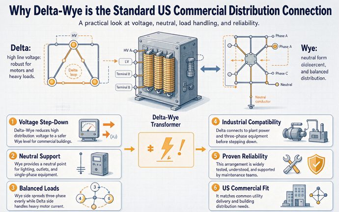
A US commercial building needs two voltages, and the utility hands it three wires with no neutral. A delta primary accepts those three wires. A wye secondary manufactures the fourth. Every other property of the connection, the 30 degree shift, the 277 volt lighting, the circulating triplen current, is a consequence of that single trade.
That sentence is the whole answer, and it is worth sitting with for a moment because it reframes the question. Delta-wye did not win a technical competition. It settled a negotiation. The utility side wanted to keep sending three wires and to keep its own grounding philosophy. The building side wanted a fourth wire it could bond to earth and split into 120 volt circuits. A transformer with a delta primary and a wye secondary is the only common arrangement that gives both sides what they asked for, and once a few hundred thousand of them were in service, the arrangement stopped being a choice and became the default that everybody prices against.
What follows is the causal chain in order. Where your utility lands on it, what that forces on the primary, why the secondary has to be wye and has to be bonded in exactly one place, where 480Y/277 actually came from, why the building then needs a second transformer instead of one big one, and what the delta primary quietly costs you in protection and in procurement. The last third is the part that shows up on a quote.
One note on scope before we start. The 1.732 arithmetic, the meter readings that identify a system on sight, and the circulating current between mismatched units are covered elsewhere and are not repeated here. This page is about why the topology is where it is, and what it charges.
The question is not electrical, it is architectural
Ask an engineer why delta-wye is standard and you usually get a list of virtues: neutral available, harmonics trapped, phase shift useful. All true. None of them answer the question, because a wye-wye has a neutral too, and a delta-delta traps harmonics just as well.
The real driver is that a commercial building is not one load. It is two load families with almost nothing in common, served from one service entrance, and the economics of each family pull in opposite directions.
Two load families, one service entrance
The first family is motors and large HVAC. Rooftop units, chillers, pumps, elevators, condenser fans. These want the highest practical low voltage, because current sets conductor size and current scales inversely with voltage. They do not want a neutral. A three phase induction motor has no use for one and would only object to it.
The second family is everything a person touches. Receptacles at 120 volts, task lighting, monitors, point of sale, coffee machines, the entire loose-load world of a tenant fit-out. This family wants a neutral and cannot work without one.
Then there is a third, quieter family: area lighting. High bay and troffers in a warehouse, corridor and parking lighting in an office. Historically these ran at 277 volts because 277 was available, and 277 is available because the service is 480Y/277.
| Load family | Voltage | Neutral needed | Share of connected load, typical office |
|---|---|---|---|
| Motors, chillers, large HVAC | 480 V three phase | No | 45 to 60 percent |
| Area and parking lighting | 277 V single phase | Yes | 10 to 20 percent |
| Receptacles, task loads, tenant equipment | 120 V single phase | Yes | 25 to 40 percent |
Put those three rows in one building and the requirement writes itself. You need 480 volts for the first row. You need a neutral for the second and third. A delta-delta gives you the first and starves the rest. A wye-wye gives you everything on paper and then misbehaves for reasons covered below. Delta-wye is the arrangement that serves both rows without an argument.
The utility does not sell you a neutral
Here is the half of the story that gets left out of most explainers, and it is the half that actually decided the topology.
The utility’s medium voltage feeder arriving at your pad mounted transformer is, in most of the United States, a three wire circuit. There is no fourth conductor to land. Even where the utility runs a four wire wye distribution system, the neutral is the utility’s, bonded at the utility’s substation, and it is not yours to re-bond at your transformer. If you specify a wye primary, you are asking for a primary neutral terminal that either has nothing to connect to or connects to something you are not allowed to bond.
So the primary choice is not free. It is dictated by what is on the pole.
What the utility hands you sets the primary
US medium voltage distribution is not one system. It is a handful of them, and they differ in exactly the property that matters here: whether a neutral exists.
| Utility system | Typical connection | Wires | Neutral available | Line ratio to 480 V | Winding ratio to 277 V |
|---|---|---|---|---|---|
| 4,160 V | Delta | 3 | No | 8.67 | 15.01 |
| 12,470 V | Delta | 3 | No | 25.98 | 45.00 |
| 13,800 V | Often 13.8Y/7,967 wye | 4 | Sometimes | 28.75 | 49.80 |
| 24,940 V | Often 24.94Y/14,400 wye | 4 | Sometimes | 51.96 | 89.99 |
| 34,500 V | Usually delta or 3 wire | 3 | No | 71.88 | 124.50 |
Read the last two columns carefully, because they are where submittals go wrong. The line ratio and the winding ratio differ by exactly 1.732 for every row. A 12,470 volt delta primary to a 480Y/277 secondary is a line ratio of 25.98 and a winding ratio of 45.00, and 45.00 is suspiciously round, which is not an accident. Transformer designers pick turns to land on the nominal secondary voltage, and 12,470 divided by 277.1 comes out at 45.0 almost exactly. That is why this particular pairing is so common and so cheap.
Three wires or four
The practical question to ask your utility, before you ask any supplier for a price, is whether the service point is three wire or four wire, and if four, whether the neutral is yours.
Three wire means delta primary, no discussion. Four wire with a utility owned neutral usually still means delta primary, because you cannot bond the utility’s neutral at your transformer without creating a second ground point on the utility system, which is not permitted and not safe. Four wire where the utility delivers a genuine separately derived service can support a wye primary, and that is the case where wye-wye or wye-delta enters the conversation at all.
Why a wye primary on a three wire feeder is a change order
If you buy a wye primary unit for a three wire feeder, three things happen, in this order. The primary neutral terminal arrives with nothing to land on. Your electrician leaves it floating, which is electrically tolerable for a balanced load and legally awkward, because a floating wye point on the primary drifts with any imbalance and puts unpredictable voltage stress on the windings. And then someone writes an RFI.
The other direction is worse. Bond that primary neutral to building ground to make it look right, and you have created a second grounding point on a system that already has one, plus a path for zero sequence current to travel between two grounded systems at different potentials. The symptom is a current on a grounding conductor that nobody can explain, and the fix is a new transformer.
Delta primary avoids the entire conversation. That is a large part of why it is standard, and it has nothing to do with harmonics.
The secondary has to be wye, and that is a code fact
The secondary side is easier, because it is not a preference. It is a rule with a voltage written into it.
250.20(B)(2) names this system by its voltage
NEC 250.20(B) lists the alternating current systems between 150 volts and 1,000 volts that are required to be grounded. One of the items is the 480Y/277 volt three phase four wire wye system, named explicitly, by voltage.
That is unusual. Most code requirements describe a class of system. This one names a product. The code is telling you that this particular arrangement is common enough, and its grounding is important enough, that it gets its own line. You do not get to decide whether to ground a 480Y/277 service. You decide how.
Once the neutral is grounded at the transformer, three things become true at once. Phase to ground voltage is pinned at 277 volts instead of floating somewhere between zero and 480. A line to ground fault has a return path and will produce current that protection can see. And every piece of equipment downstream can be built for 277 volts of insulation to ground rather than 480.
That last one is worth money. A 480 volt corner grounded delta puts 480 volts to ground on two of its three phases. Every conductor, every terminal block, every surge arrester, every motor winding in that plant is stressed at 480 volts to ground, not 277. The insulation systems are not the same product and the price is not the same price.
One bond, at the transformer, and nowhere else
A delta-wye transformer is a separately derived system. There is no conductive path between the primary and secondary windings, only magnetic coupling. That means the secondary is a brand new power source with no ground reference of its own until you give it one, and 250.30 tells you how: a system bonding jumper from X0 to the enclosure and to the equipment grounding conductor, a grounding electrode conductor sized from Table 250.66 on the derived phase conductors, and a connection to a grounding electrode.
Then the important part. After that single bond, the neutral is a neutral. It does not get bonded to ground again in any downstream panel. Every additional neutral to ground bond creates a parallel path, and the neutral current, which is normal operating current, divides between the neutral and the grounding conductors, the conduit, the building steel, and anything else metallic that happens to be continuous. The result is a shock hazard, a fire hazard in a loose connection, and enough stray current to make every sensitive load in the building behave strangely.
The night the 277 volt drivers saw 480
Here is what a missing bond looks like in practice, because the failure is violent and it arrives at night when nobody is watching.
A 1,000 kVA, 12,470 delta to 480Y/277 pad mounted unit feeds a retail building. Rooftop units on 480 volt three phase, interior lighting on 277 volt single phase. The electrician lands the secondary phase conductors on X1, X2, X3 and runs the neutral from X0 to the neutral bus. He does not install the system bonding jumper, so X0 is connected to the load side but not to the enclosure or to the electrode system. The neutral is floating, which means the star point has no fixed relationship to earth.
The building energizes. Nothing happens, because a floating neutral with a balanced load sits near zero volts by symmetry. Then a phase to ground fault occurs on phase B, outside the building, on the service lateral. Current flows from B through the fault to earth and back through the grounding electrode system to the transformer case, and from there to X0 through capacitance, leakage, and whatever incidental paths exist. The star point does not stay put. It shifts toward phase B, because phase B is now tied to earth.
The other two phases do not move. Their voltage to the shifted neutral rises from 277 toward the full 480 volts line to line. Every 277 volt driver on phases A and C gets somewhere between 277 and 480 volts applied to it. The rooftop units on 480 volt three phase keep running, because their line to line voltage never changed. That is the signature of this fault: three phase equipment fine, single phase electronics destroyed, and the building’s own service looking perfectly normal.
The arithmetic is worth writing down because it tells you the margin. A driver rated 277 volts nominal with a 300 volt maximum sees 480 volts, which is 173 percent of nominal and 160 percent of its absolute limit. There is no recovery from that. The failure is not gradual and it is not covered by any surge rating.
Where 480Y/277 came from
Most pages assert 480Y/277 as though it were handed down. It was not designed. It fell out of two earlier decisions that had nothing to do with each other.
480 is twice 240, and 277 is what falls out
The chain starts at the lamp. The American lighting standard settled at 120 volts utilization, descended from Edison’s 110 volt DC systems and the 110/220 volt AC systems that replaced them. Residential service is 120/240 single phase, and it has been for a century.
When commercial buildings went three phase, the phase to neutral voltage had to stay at 120 volts, because that is what the lamps, the receptacles, and the appliances were built for. Three phase four wire with 120 volts to neutral gives 208 volts line to line, because 120 times 1.732 is 207.8. Nobody chose 208. It is the only number that lets you keep 120.
Separately, motor voltage roughly doubled after the war years, from 220/440 to 230/460, and eventually to the 460 volt utilization voltage that NEMA MG 1 still lists for a 480 volt nominal system. The 480 came from that direction, doubling 240 for the same reason every other voltage doubled: twice the voltage, half the current, half the copper.
Then the two decisions met. A 480 volt three phase four wire system has a phase to neutral voltage of 480 divided by 1.732, which is 277.1. Nobody sat down and picked 277. It is the residue of 480 and a square root.
The reversal: lighting was built for 277
This is the part that almost nobody says out loud, and it flips the usual explanation.
The standard telling is that 480Y/277 was chosen because 277 volts is efficient for lighting. That is backwards. 480Y/277 exists because 480 was already there for motors and a neutral was needed for other reasons. The lighting industry then built 277 volt ballasts because the voltage was sitting there, unclaimed, and using it saved a transformer.
Once they did, the advantage became real and permanent. A 20 ampere circuit at 120 volts delivers 2,400 volt amperes, and at the 80 percent continuous limit, 1,920. The same circuit at 277 volts delivers 5,540 volt amperes, and at 80 percent, 4,432. That is 2.31 times the load on identical wire and an identical breaker, because 277 divided by 120 is 2.31, which is the same ratio as 480 divided by 208.
The circuit count arithmetic
Put numbers on it, because the ratio is abstract and the panel count is not.
A 100,000 square foot office at 0.9 watts per square foot for lighting carries 90 kW. At 120 volts, each 20 ampere circuit carries 1,920 volt amperes, so you need 47 circuits. At 277 volts, each circuit carries 4,432 volt amperes, so you need 21.
Forty seven breakers do not fit in one 42 circuit panelboard. You buy two panels, two feeder runs, two sets of conduit, and you give up 84 panel spaces to serve lighting. Twenty one breakers fit in one panel with room left over. The saving is not in the wire gauge, since both cases use the same conductor for 16 amps. It is in the panel count, the home runs, the conduit fill, the labor hours, and the wall space in an electrical closet that a tenant will eventually want back.
| Lighting load, 90 kW | 120 V | 277 V |
|---|---|---|
| Volt amperes per 20 A circuit at 80 percent | 1,920 | 4,432 |
| Circuits required | 47 | 21 |
| 42 circuit panelboards | 2 | 1 |
| Breaker spaces consumed | 47 | 21 |
| Home runs to pull | 47 | 21 |
Why universal drivers changed the argument
For thirty years the 277 volt lighting argument was airtight because a fluorescent ballast was a single voltage device. You bought 120 volt ballasts or 277 volt ballasts, and if you bought the wrong one you ate it.
LED changed that quietly. Most drivers in commercial fixtures today are rated 120 to 277 volts, or 120 to 347, with a wide input range. The fixture does not care which of the two you feed it. What that means is the 277 volt decision is now purely an economic one about circuit count and panel space, not a compatibility one. It also means the failure mode changed: a driver on a floating neutral still dies at 480 volts, but the same driver will happily run all day on 208, which is why the “it must be 277” reflex is worth re-examining on a per-project basis.
Two tiers, and why one tier fails
If 480Y/277 is the service, why does the building need a second transformer at all? Why not serve the 120 volt receptacles from the same 480Y/277 unit through a small step-down at each floor, or just run everything at 208Y/120 from a single big transformer?
Because the two options trade copper against switchgear, and the trade is lopsided in both directions.
What 208 costs in copper
Hold the load constant and change only the voltage. A 500 kVA load at 480 volts draws 601 amperes. The same 500 kVA at 208 volts draws 1,388 amperes. The ratio is 2.308, and it applies to every size on the ladder.
Current is what you pay for three times over. Conductor ampacity scales with current, so the copper cross section roughly doubles. Voltage drop across a given conductor is proportional to current, so it also doubles, which means long feeders at 208 volts need disproportionately larger conductors to stay inside the 3 percent branch and 5 percent total limits that designers work to. And resistive loss goes with the square of current, so 2.308 times the current means 5.33 times the loss in the same conductor.
| Same 500 kVA | At 480 V | At 208 V | Ratio |
|---|---|---|---|
| Line current | 601 A | 1,388 A | 2.31 |
| Voltage drop, same conductor | 1.0 | 2.31 | 2.31 |
| Resistive loss, same conductor | 1.0 | 5.33 | 5.33 |
| Feeder ampacity needed | 751 A | 1,735 A | 2.31 |
A 751 ampere feeder is four sets of 4/0 in parallel, or a 800 ampere busway. A 1,735 ampere feeder is eight sets, or a 2,000 ampere busway, and the busway is not a small line item. This is the entire reason a 480 volt distribution bus exists in a large building: it lets you move bulk power around the building at a current you can afford to carry, and step down only where the load actually needs 120 volts.
What 208 saves in switchgear
Now the other direction, and this is the half that never gets written down.
Fault current at the service bus is set by transformer kVA and impedance. A 1,000 kVA unit at 5.75 percent impedance on a 480 volt bus produces 20.9 kA of available fault current. Switchgear and breakers at that bus have to be rated for it, so you are buying 25 kA equipment, which is a real premium over 10 kA and a real constraint on which manufacturers and which frame sizes you can use.
Step down through a 75 kVA dry type at 3.5 percent impedance to 208Y/120 and the fault current at that panel is 5.95 kA. Now every panelboard downstream of it can be a standard 10 kA panelboard, which is the cheapest, most stocked, most substitutable electrical equipment in North America.
That is the second reason for two tiers, and it is the one with the biggest line item attached. The step-down transformers are not there only to change voltage. They are there to insert impedance between a 20.9 kA bus and a hundred panelboards, so the hundred panelboards can be commodity parts.
| Point in the system | Available fault current | Equipment rating you must buy |
|---|---|---|
| 480 V bus, 1,000 kVA at 5.75 percent | 20.9 kA | 25 kA switchgear |
| 480 V bus, 500 kVA at 5.75 percent | 10.5 kA | 14 kA or 18 kA |
| 208 V panel, 75 kVA at 3.5 percent | 5.95 kA | 10 kA panelboard |
| 208 V panel, 112.5 kVA at 3.5 percent | 8.92 kA | 10 kA panelboard, check the series rating |
A 100,000 square foot floor, costed
Put the tiers together on a realistic floor plate.
Lighting is 90 kW at 277 volts, which is 21 circuits and one panelboard, fed from the 480Y/277 bus. It never touches the 208 volt system at all. This is the design most people miss: in a modern building, lighting does not go through the step-down transformer.
Receptacle and tenant load is 150 kW at 120 volts. At a 0.9 power factor that is 167 kVA, which is two 100 kVA dry types or three 75 kVA units, distributed rather than central, because the load is spread across the floor and 208 volt feeders are the expensive kind. One 167 kVA central unit would need a 464 ampere feeder at 208 volts. The same 167 kVA moved at 480 volts needs 201 amperes, and 480 volt busway is cheaper per ampere than 208 volt conduit and wire.
So the pattern is: bulk power moves at 480, lighting taps 277 directly off it, and dry types are scattered where the receptacles are. That is the standard US commercial distribution architecture, and delta-wye is what makes each piece of it available.
What the delta primary buys
Now to the four virtues, but with the arithmetic attached, because the list alone is what everybody already writes.
It blocks zero sequence
Zero sequence current is the component that flows in phase on all three conductors. It is what a line to ground fault produces, and it is what triplen harmonics produce.
A delta winding is a closed loop with no neutral connection. Zero sequence current has no terminal to enter or leave by, so it cannot cross the transformer. It circulates inside the delta and dies there as heat in the winding resistance. From the utility’s point of view, the transformer is a wall.
That wall has two consequences, one good and one that will cost you money later in this page. The good one is that harmonics generated downstream stay downstream. The bad one is that a ground fault on the secondary cannot be seen clearly from the primary, and we will come back to that.
It swallows the triplen current
Third, ninth, and fifteenth harmonics are triplen. They are in phase on all three phases by definition, so they add in the neutral instead of cancelling.
On a 480Y/277 system feeding a floor of LED drivers and switching supplies, a third harmonic content of 15 percent of the fundamental on each phase puts 45 percent of the phase fundamental current on the neutral, because the neutral carries three times the third harmonic. At 33 percent third harmonic the neutral equals the phase current, and above that the neutral is carrying more than any phase.
On a delta-wye unit, those currents arrive on the neutral, travel into the wye winding, and then circulate in the delta primary rather than propagating up the utility line. The utility sees a clean load. Your upstream service transformer does not overheat from a harmonic spectrum it was not designed for. And your neighbors on the same feeder do not see your distortion.
That is a genuine benefit and it is why data centers and offices with high electronic load density are almost universally delta-wye. It is also why the neutral is not a minor conductor. More on that below.
It lets the utility keep its grounding philosophy
The delta primary is indifferent to how the utility grounds its own system. Ungrounded, resistance grounded, corner grounded, solidly grounded wye, the primary does not care, because it has no neutral terminal to argue with.
This is a bigger deal than it sounds. Utility medium voltage practices vary by region and by company, and a transformer that requires the utility to change its grounding to accommodate your building is a transformer that generates meetings. The delta primary accepts whatever arrives and provides a clean, freshly grounded reference on the other side. That is the interface function, and it is arguably the single strongest reason the topology is universal.
It is half of every 12 pulse drive
A six pulse rectifier produces characteristic harmonics at the fifth, seventh, eleventh, and thirteenth, at roughly 20, 14, 9, and 7.7 percent of fundamental for a typical drive.
Feed a twelve pulse rectifier from two six pulse bridges, one fed by a delta secondary and one by a wye secondary of the same transformer, and the two sets of fifth and seventh harmonics are 180 degrees apart. They cancel. What remains is the eleventh and thirteenth.
Delta-wye is one half of that pair. Any twelve pulse drive input transformer in the world is a three winding unit with a delta and a wye secondary, and the delta-wye connection is not an incidental feature of it, it is the mechanism.
What the delta primary costs
Now the bill. Three items, and they are the reason a delta-wye is not simply better than everything else.
A secondary ground fault lands on two primary phases at 58 percent
This one is worth working through, because it is the least understood property of the connection and it has direct protection consequences.
Take a 1,000 kVA, 12,470 delta to 480Y/277 unit at 5.75 percent impedance. A bolted three phase fault on the 480 volt bus produces 20.9 kA. The primary full load current is 46.3 amperes, and the fault referred to the primary is about 805 amperes, which is 17 times full load. Any primary device will see that.
Now make it a single line to ground fault on the wye side instead. The fault current itself is still large, close to the three phase value, because the transformer’s own impedance limits it and the delta provides the circulating path for the zero sequence component inside the transformer.
But watch what the primary sees. Zero sequence cannot cross the delta, so only the positive and negative sequence components transform. Those two components shift in opposite directions across the connection, plus 30 degrees and minus 30 degrees. When they recombine on the primary side, the result is that one phase carries nothing, and the other two carry 58 percent each of what a balanced fault of the same magnitude would have produced.
Fifty eight percent is one over the square root of three. It is not an approximation, it is exact.
| Secondary fault, 1,000 kVA delta-wye at 5.75 percent | Value |
|---|---|
| Bolted three phase fault, 480 V bus | 20.9 kA |
| Primary full load current at 12,470 V | 46.3 A |
| Three phase fault referred to primary | 805 A, all three phases, 17 times full load |
| Same fault as line to ground, primary per phase | 465 A, two phases only, 58 percent |
| A 300 A arcing ground fault, primary per phase | 6.7 A, two phases only, 14 percent of full load |
Read the last row again. A 300 ampere arcing ground fault on a 480 volt system is a serious event. It will destroy a busbar joint and start a fire. On the primary of this transformer it presents as 6.7 amperes on two phases, which is 14 percent of full load current. No primary overcurrent device on earth is set to trip at 14 percent of full load, because that would trip on normal load.
The current is there. It is simply not visible from where the protection is.
Which is why 230.95 exists
This is the mechanism behind a code requirement that looks arbitrary until you understand the transformer.
NEC 230.95 requires ground fault protection of equipment on solidly grounded wye services, more than 150 volts to ground and not more than 600 volts phase to phase, rated 1,000 amperes or more. The pick up cannot exceed 1,200 amperes, and there is a maximum delay that shortens as the fault current rises. 215.10 applies the same idea to feeders.
The requirement exists because a delta-wye service at 480Y/277 is grounded, which is what makes line to ground faults possible in the first place, and because the delta primary cannot see a low level one from the utility side. So the protection has to be local, on the secondary, looking at the residual current directly.
Follow the chain and it is entirely deterministic. The building needs a neutral, so the secondary is wye. A wye secondary is grounded, because 250.20(B)(2) says so. A grounded system can have a line to ground fault. The delta primary hides a low level one. Therefore you install ground fault protection. Every step follows from the one before it, and none of it is arbitrary.
The clock number is a purchase order field
A delta-wye transformer has a phase displacement between primary and secondary. In IEC 60076-1 clock notation it is written as a vector group, and the two you will meet are Dyn1 and Dyn11.
The letters say delta primary, wye secondary with a brought out neutral. The number says where the secondary phase to neutral voltage vector sits on a clock face relative to the primary. One o’clock and eleven o’clock are 60 degrees apart, not 30, which is the detail that catches people who assume the numbers are adjacent so the difference must be small.
North American practice generally builds Dyn1. European and Asian practice generally builds Dyn11. Neither is wrong. They are conventions, and each is internally consistent.
The trouble is procurement. A European supplier quoting a US project will often propose Dyn11 because that is what their production line is set up for, and it will look fine on a submittal until someone tries to parallel it with an existing Dyn1 unit, or until a relaying scheme assumes a particular displacement. The check is a single line item on the RFQ, and it costs nothing to specify and a great deal to discover later.
The same field also matters for the twelve pulse story above. A twelve pulse transformer needs one delta and one wye secondary on the same core, which is a three winding unit, not two separate transformers. If you buy two separate units to save money, you get two independent phase displacements that will not be 30 degrees apart unless you specify them that way.
The neutral became a design variable
A wye secondary gives you a neutral, and the neutral is not a free wire. It is a conductor with an ampacity, and the load decides whether that ampacity is adequate.
For a conventional balanced three phase four wire load, the neutral carries only the imbalance, and 220.61 lets you size it below the phase conductors. For a load dominated by electronic supplies, the neutral carries the sum of the triplen harmonics, which can exceed the phase current. 310.15(E) requires the neutral to be counted as a current carrying conductor for ampacity adjustment where the harmonic content is significant.
The design answer for a harmonic heavy floor is a 200 percent neutral, meaning the neutral bus and the neutral conductor are rated at twice the phase ampacity. It costs real money in copper and in the neutral bus of every panelboard and every transformer. It is also the difference between a system that runs for twenty years and one that cooks its neutrals in five.
If you are buying a delta-wye unit for a data center, a lab, or a floor full of LED drivers, the neutral rating belongs on the RFQ right next to the kVA.
The four systems you will actually meet
Everything above explains one system. In the field you will meet four, and each has its own cost structure and its own RFQ language.
| System | Where it shows up | What it costs you | What to write on the RFQ |
|---|---|---|---|
| 480Y/277, 3 phase 4 wire | Standard commercial and industrial service, large buildings | 277 V insulation to ground, GFPE required at 1,000 A and above, 25 kA switchgear at typical sizes | Delta primary, wye secondary with full neutral, Dyn1, 5.75 percent, 25 kA bus |
| 208Y/120, 3 phase 4 wire | Step-down tier, small commercial, older buildings with no 480 | 2.31 times the current for the same kVA, feeder cost, 120/208 slash rated breakers on some circuits | Delta primary 480 V, wye secondary 208Y/120, 3.5 to 5.75 percent |
| 240 high leg delta, 3 phase 4 wire | Older light industrial, rural co-op service, machine shops | Only one winding can supply 120 V, so line to neutral capacity is about a third of the kVA, and the high leg sits at 208 V to ground | Center tapped delta, 120/240, high leg marked orange, phase B |
| 240 or 480 corner grounded delta | Legacy industrial, some utility services, occasional crane and hoist work | 240 or 480 V to ground on two phases, slash rated breakers, no 120 V without a separate transformer | Corner grounded delta, note the grounded phase, full voltage rated breakers |
The high leg row deserves a comment because it is the one that gets misapplied most. A 240 volt center tapped delta gives you 120 volts from A to neutral, 120 volts from C to neutral, and 208 volts from B to neutral, which is 120 times 1.732. If you land a 120 volt circuit on B, you put 208 volts on it. The code requires that leg to be identified, phase B by convention, marked in orange, and the enclosure field marked with the voltage to ground. The load you can serve at 120 volts is limited by the capacity of that one center tapped winding, which is a fraction of the bank.
The corner grounded rows are the ones where insulation class quietly doubles. Two phases sit at full line voltage to ground. Every device on those phases needs to be rated for the full voltage to ground, not the slash rating that lets you use a 240/120 breaker on a 120 volt to ground system. If you inherit one of these, price the breakers before you price anything else.
The twelve lines that get you the right unit
Everything in this page collapses into a specification. If you write these twelve lines, you will get a unit that fits, and if you omit any of them, you will get a unit that almost fits.
- kVA and cooling class. Liquid immersed or dry type, and the standard rating you want, not a rounded up number with no basis.
- Primary voltage, connection, and BIL. 12,470 delta, 95 kV BIL, for example. The connection is not implied by the voltage.
- Secondary voltage and connection. 480Y/277, four wire, with the neutral brought out to X0. Write “wye” explicitly.
- Vector group. Dyn1 for North American practice, unless there is a documented reason for Dyn11.
- Percent impedance, and the tolerance. 5.75 percent plus or minus 7.5 percent is a common commercial band. Impedance drives fault current, and fault current drives your switchgear.
- Tap range and steps. Two 2.5 percent steps above and two below is the usual commercial request. Taps are how you compensate for a utility that delivers 12,200 instead of 12,470.
- Temperature rise and insulation class. For dry type, 150 degrees C rise on a 220 degree C system is a different product from 80 degrees C rise on a 150 degree C system, at the same kVA.
- Neutral rating. Full neutral or 200 percent, and say which.
- Efficiency basis. Current DOE table now, and the 2029 values if your energization date is anywhere near it.
- Enclosure and sound level. dBA at a stated distance, because a unit that meets its electrical spec and misses its acoustic spec still fails the submittal.
- SCCR of the assembly, if the transformer is being supplied with a disconnect or a primary switch.
- Applicable standards and the edition. IEEE C57.12.01 for dry type, C57.12.00 for liquid, and the year of the edition you are holding the supplier to.
That last one matters more than it looks. Two suppliers quoting to two different editions of the same standard are not quoting the same product, and the difference shows up in the test report, not the price.
Four things that go wrong on the submittal
These are the four that repeat, in roughly this order of frequency.
A wye primary offered for a delta feeder. Usually because the supplier’s catalog default is wye primary for a certain kVA range, or because the sales engineer read the utility voltage and not the utility connection. The catch is on the primary connection field, and it is caught by comparing the quote against the utility’s service letter, not against your own one line, because your one line is where the error started.
A Dyn11 offered against a Dyn1 plant. Common with imported units. It is not a defect, and it will pass every factory test. It becomes a defect the day someone closes a tie breaker between it and an existing unit, or the day the differential protection is commissioned.
A 100 percent neutral on a harmonic heavy floor. The transformer arrives correct and the panels downstream cook. The neutral current shows up as heat at the terminations and as voltage distortion at the loads, and by the time anyone measures it, the neutral bars have been running hot for a year.
An impedance low enough to blow the panelboard budget. A supplier quoting 3.5 percent on a 480 volt unit to win on losses hands you 34 kA at the bus instead of 20.9, and every downstream device rating moves up a class. Low impedance is not free, it is merely paid for by someone else on the project.