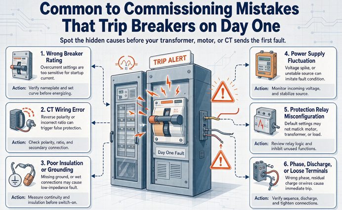
Most day one trips are not transformer faults. They are a breaker sized by a rule that never looked at the first half cycle, a neutral bonded to ground in two places, or a shunt trip with no control power. The timestamp on the trip tells you which one you have. Start with the clock, not the checklist.
Nobody calls a commissioning engineer at nine in the morning to say the gear works. The call comes when the main closes and something opens it again twenty seconds later, and by the time you arrive the crew has already tried it four times, and the fourth attempt is the one that worries me, because three failed closes have put heat into a bimetal and residual flux into a core and taught nobody anything.
Here is the thing that separates a two hour fix from a two day one. A trip is not a verdict on the transformer. It is a timestamp, and the timestamp narrows the cause from twelve candidates to about three before you open a single panel. That is the whole method on this page, and it is the opposite of how commissioning is usually written about, which is as a sequence of checks running forward from the delivery truck. Sequences are fine when nothing has gone wrong. On the day something goes wrong you need the list sorted the other way.
Twelve mistakes follow, in rough order of how often they take down a first energization. Each one comes with what it looks like, why the arithmetic produces it, and the test that settles it. None of them require you to distrust the transformer, because in my experience the transformer is at fault in a small minority of these calls, and the minority is easy to spot once you know the clock.
The trip time is the diagnosis
Every protective device has a thermal mass, and the mass sets how long it takes to act. A shunt trip coil is wire and a plunger, so it acts in a fraction of a cycle. A magnetic element responds to the peak, so it acts inside the first cycle. A bimetal has to heat, which takes tens of seconds to minutes. A winding has to heat a mass of copper, which takes hours. So the time between the close and the trip is not noise. It is a reading.
| Time from close to trip | What it can be | First thing to check |
|---|---|---|
| Under 30 ms, sometimes with no sound at all | Shunt trip energized, undervoltage release not powered, trip free mechanism, close coil wired into the trip circuit | The trip circuit and the control power source, not the transformer |
| One half cycle to one second | Inrush against the instantaneous element, a differential element with no harmonic restraint, a secondary short, a phase to ground fault from installation damage | Whether the LV main was open, and the relay event record |
| One to thirty seconds | A slow thermal element riding a long inrush, a motor starting on top of transformer inrush, a resistive secondary fault | What else closed at the same instant |
| One to thirty minutes | Cold load pickup, a tap on the wrong position, cooling that never started, load applied in one block | The load, not the breaker |
| One hour to one day | A double neutral bond that only shows up once current flows, a real thermal overload, an ambient above the design | Neutral current on the grounding electrode conductor, and the room temperature |
Read that table the way you read a meter. A trip at 20 milliseconds and a trip at 20 minutes have almost nothing in common except that both are called a trip, and treating them as one problem is how crews end up replacing a breaker that was working correctly.
One caution before the list. A trip that happens once and does not repeat is a different animal from a trip that happens every single time. The first is a margin problem, and margins depend on variables you do not control. The second is a defect or a setting. Decide which one you have before you decide what to fix, because the two answers point in opposite directions and the wrong one costs a day.
Mistake one: you energized with the load still connected
The correct first close is a no load close. High side closed, low side main open, secondary voltage verified, then the low side main closed, then the branches, then the load in blocks. Almost everyone knows this. A fair number of crews skip it, not out of carelessness but because the low side main was already closed from the pull, nobody wrote the sequence down, and the first person with a hand on the switch is an electrician who was told to “see if it comes up.”
What you are stacking when you skip the step is not just the transformer. It is every load that starts at the same instant.
- Transformer magnetizing inrush, 8 to 12 times full load current, decaying over roughly 0.1 to 1 second.
- Locked rotor current on every motor, about 6 times its own full load current for the first second and longer on a big one.
- DC bus charging on every drive, which looks like a short circuit for the first two to five cycles and then stops.
- Contactors, relays, control transformers, and every coil on the lineup.
- Capacitor banks, at 3 to 20 times their rated current for a cycle or two.
- Charging current on long cable runs, which is small per run and adds up across a building.
Run the numbers on a 500 kVA unit at 480 volts. Full load current is 601 amps. At 12 times inrush that is 7,217 amps, against an 800 amp breaker with an instantaneous element at 8,000 amps. The margin is eleven percent before anything else closes. Now add one 150 horsepower motor at 180 amps full load and 6 times locked rotor, which is 1,080 amps, and four 30 kW drives charging their DC buses, and the sum walks straight through 8,000 amps without the transformer doing anything unusual.
That is the whole mechanism. The transformer was fine, the breaker was fine, and the design was fine on paper because the paper assumed the load came on after the transformer was already magnetized. The fix is one extra step and about thirty seconds. Close the high side with the low side main open, listen, read the secondary voltage, then close the low side.
There is a second reason to do it this way that has nothing to do with tripping. A no load close is the only moment you get to hear the core by itself. A steady hum at the fundamental is normal. A rattle, a buzz with a beat in it, or a sound that changes character when the load comes on is information you will never get back once the building is running, and it is the kind of information that tells you to stop before the second day.
Mistake two: the breaker is sized right and still trips
This is the one that ends arguments, so let us do it properly.
Where the 12.5 comes from
NEC 450.3(B) allows the primary overcurrent device on a transformer to be set at up to 125 percent of the rated primary current, with the next higher standard rating permitted when 125 percent does not land on a standard size. That is the rule every designer follows, and it is a thermal rule. It exists to let the transformer carry its rated load without nuisance operation. It says nothing about the first half cycle.
Then the breaker itself. A thermal magnetic molded case breaker has an instantaneous element, and a very common factory setting is 10 times the breaker’s own rating. Multiply the two and you get the ceiling:
125 percent times 10 equals 12.5 times the transformer’s full load current. That is the highest current the magnetic element will tolerate before it trips, expressed in transformer terms.
The table below runs a little higher than 12.5 in the last column, and the reason is the second half of the same rule. When 125 percent of the primary current does not land on a standard device rating, the code permits the next size up, so a 500 kVA unit at 601 amps goes to a 752 amp calculation and then to an 800 amp breaker, which is 1.33 times full load rather than 1.25. That rounding up is why the real threshold is a range and not a single number.
| Transformer | Full load amps at 480 V | 125 percent | Standard breaker | Instantaneous at 10x | That is, in transformer FLA |
|---|---|---|---|---|---|
| 75 kVA | 90 | 113 | 125 A | 1,250 A | 13.9x |
| 500 kVA | 601 | 752 | 800 A | 8,000 A | 13.3x |
| 750 kVA | 902 | 1,128 | 1,200 A | 12,000 A | 13.3x |
| 1,000 kVA | 1,203 | 1,504 | 1,600 A | 16,000 A | 13.3x |
| 1,500 kVA | 1,804 | 2,255 | 2,500 A | 25,000 A | 13.9x |
Look down the last column. It barely moves. The trip threshold is a property of the sizing rule, not of the hardware, which is why the same complaint shows up on a 75 kVA dry type in a strip mall and on a 1,500 kVA unit in a plant. And the inrush on a modern grain oriented core runs 8 to 12 times full load current, which means the margin between the two numbers is somewhere between comfortable and nonexistent, and on a bad day negative.
The offset is what actually trips it
The instantaneous element does not respond to the symmetrical current you read off a nameplate. It responds to the peak, and the first cycle of an inrush is not symmetrical. The core is saturated, the current is unidirectional on the first half cycle, and the peak is up to twice the symmetrical peak because of the DC offset that comes with closing into an inductive circuit.
So a 12 times inrush does not present 12 times to the element. It presents something higher, and how much higher depends on the breaker, the offset, and how fast the element integrates. Our own arithmetic puts the effective value between 1.3 and 1.7 times the symmetrical figure, which moves the crossing point down to somewhere between 7 and 10 times full load current. Call it 9 as a working number.
That gives you a usable rule, and it is the most useful sentence in this article.
Below about 7 times full load current, a correctly sized thermal magnetic breaker will hold. Above about 10 times, it will trip. Between 7 and 10, the closing angle decides.
Two identical transformers from the same factory, in the same building, on identical breakers, will land on opposite sides of that line depending on the day. That is not a warranty issue and it is not a design error. It is a margin of four percent being asked to absorb a variable that swings by fifty.
Why the same unit closes on the fourth try
The variable is the point on the voltage wave where the contacts touch, and the arithmetic is short enough to do on a napkin.
Flux is the integral of voltage, so the flux in the core lags the voltage by a quarter cycle. When you close at the instant the voltage passes through zero, the flux has to start from wherever it was and swing all the way to the opposite peak, which is twice the normal peak. When you close at the instant the voltage is at its peak, the flux only has to travel the normal peak. Add whatever flux was already trapped in the core from the last time it was energized and you have the peak flux for that close:
peak flux = residual flux + peak flux at rating times (1 + cosine of the closing angle)
| Closing angle | Peak flux, with residual at 0.7 | What happens |
|---|---|---|
| 0 degrees, voltage crossing zero | 2.70x normal | Deep saturation, inrush at the top of the range |
| 30 degrees | 2.57x normal | Still deep, still trips |
| 45 degrees | 2.41x normal | Marginal |
| 60 degrees | 2.20x normal | Usually holds on a small unit |
| 90 degrees, voltage at peak | 1.70x normal | Inrush near the bottom of the range |
A core saturates at roughly 1.1 to 1.2 times its rated peak flux, so every one of those numbers is past the knee. What changes is how far past, and inrush current is a steeply nonlinear function of how far past. Twice the flux is not twice the current. It is several times the current.
Now the residual. When a breaker interrupts at current zero, which is where it is designed to interrupt, the flux is at its peak at that instant and it gets trapped, because there is no current left to drive it back down. On grain oriented steel that trapped flux runs about 0.6 to 0.8 of the peak, and it decays over minutes to hours. So the second attempt does not start from zero. It starts from wherever the first attempt left the core, in whichever direction, and that is why attempt two can be worse than attempt one and attempt four can be fine.
A half cycle at 60 Hz is 8.33 milliseconds. The closing angle of a spring driven breaker scatters across a few milliseconds, which is tens of electrical degrees, and at 480 volts nobody is controlling it. There is no point on wave control on a molded case breaker and there will not be.
So here is the diagnostic that saves the day.
If it holds on the second or third attempt, you do not have a fault. You have a margin problem. If it trips every single time from the first attempt to the tenth, you have a fault or a setting, and no amount of retrying will change it.
Write that on the panel and stop the retry loop, because the retry loop itself is a small harm. Each attempt puts another duty cycle into the winding, which moves conductors that were not designed to move that often, and heats the bimetal so the next attempt is more likely to trip for a different reason than the first.
Three fixes that work and one that does not
The fixes, in order of cost:
- Check the magnetic setting before you change anything. A lot of molded case breakers in the 250 to 1,000 amp range have an adjustable instantaneous band, often 5 to 10 times, and the factory ships it at the bottom of the band. Turning it to the top costs nothing and buys you a factor of two on the only number that matters here.
- Use a breaker with a short time delay. An electronic trip unit lets you turn the instantaneous off or set it at 12 times, and put a short time band at 6 to 8 times for 0.1 to 0.3 seconds. Inrush decays inside that window, so the breaker rides through it. The ceiling is the transformer through fault damage curve, IEEE C57.109, and for a Category II distribution unit there is only a second or two of thermal capability at 12 times, so this is not a knob you can turn freely. It is a fix for inrush, not a licence to ignore coordination.
- Use a time delay fuse. A Class J time delay fuse holds 12 times its rating for well over a tenth of a second without opening, which is exactly the shape of the problem. This is the cheapest fix available and the one crews miss most often, because when a fuse opens they replace it like for like from the truck and never look at the curve.
The fix that does not work is a bigger transformer. The ratio in the table above is set by the 125 percent rule, so a 750 kVA unit on a 1,200 amp breaker has the same 13.3 to 1 relationship as a 75 kVA unit on a 125 amp breaker. Upsizing moves the problem, it does not solve it, and it costs a lot more than a fuse.
Mistake three: the neutral is bonded to ground twice
A transformer with a wye secondary is a separately derived system, and NEC 250.30 requires the neutral to be bonded to ground at the transformer, once. Downstream of that point the neutral is a current carrying conductor and it is not bonded again. That is the rule. The second bond is the mistake, and it is the most common cause of ground fault protection tripping on a system with nothing wrong with it.
It happens for understandable reasons. A crew that spends most of its time on services bonds the neutral in the first panel because that is what you do at a service. A piece of equipment arrives with a factory installed bonding strap from neutral to ground on its terminal block. Somebody adds a receptacle fed from a four wire circuit and lands the neutral and ground on the same bar because there was only one bar. A generator is tied in and its neutral is bonded at the generator as well as at the service.
However it gets there, the electrical result is the same. Normal neutral current now has two paths back to the source, the neutral conductor and the ground path, and current divides between them the way current divides between any two resistors in parallel. The ground path is not supposed to carry current, so nobody sized it for that, and the zero sequence sensor that watches for ground faults now sees the difference between what went out on the phase and what came back on the neutral.
Put numbers on it. A 480Y/277 service carrying 400 amps of unbalanced neutral current, with a bond at both ends, will push a meaningful fraction of that 400 amps onto the grounding conductors. Half is a reasonable estimate on a run with a lot of conduit and building steel in parallel. That is 200 amps of current the sensor reads as a ground fault, on a device set at 200 amps because the study said the arcing fault current would be higher than that. It trips. There is no fault. There is a screw.
Note the timing. This one does not trip at energization. It trips when the load arrives, which is why it lands in the minutes to hours bucket and why crews misdiagnose it as an overload or a bad breaker.
Three tests, in order:
- Clamp the grounding electrode conductor with the unit loaded. It should read essentially zero. A few amps means something is using ground as a return path.
- Lift the main bonding jumper and ohm from neutral to ground at the far end. It should read open. A low resistance means a second bond exists.
- Look for the green screw. In a panelboard that is fed from a transformer rather than from a service, the factory bonding screw should be removed. It is often not.
The fix is to find the second bond, not to raise the pickup. Raising the pickup until the nuisance stops is how you turn a working protective device into decoration.
Mistake four: the breaker closes and immediately opens
This one has a signature that is impossible to confuse with anything else once you have seen it. There is no bang, no arc, no smell, and no fault current. The handle goes to ON and comes back to OFF or to tripped in less time than it takes to let go of it.
Three causes, all in the control circuit.
A shunt trip that is energized. A shunt trip is a coil that trips the breaker when it is fed. It gets fed by a fire alarm relay, a remote stop, a building automation contact, or an emergency stop button. If that contact is closed and the coil has power, the breaker closes and the coil fires it in under 100 milliseconds. This is correct behaviour from a device doing exactly what it was told. The problem is that the contact was supposed to be open.
An undervoltage release with no control power. A UVR holds the breaker closed and will not let it close unless its coil is energized. Lose the control power and the breaker will not latch, which looks identical to a trip from the outside.
Control power taken from the load side. This is the one that eats afternoons, and it is common on packaged substations and on any lineup where the control power transformer was relocated during a redesign. The control transformer that feeds the breaker’s own closing and trip circuits is connected to the transformer secondary, on the load side of the breaker. The breaker cannot close because the UVR has no power. The UVR has no power because the breaker is open. The loop is complete and no amount of retrying will break it, which is why this one produces the “it will not even hold” call rather than the “it trips” call.
The test takes thirty seconds and does not require a drawing. Put a meter across the trip circuit and watch it while someone closes. Or, with the breaker open, disconnect the shunt trip lead and close. If it holds with the lead off, you have found it. Then go find out why the contact was closed, because the answer is usually a relay in the wrong state or a jumper somebody left in during testing.
One more, which is not a control problem. If the handle will not stay in even with the trip circuit completely dead, the mechanism is trip free or the latch is not engaging. That is a breaker problem, and no amount of wiring work will fix it. The test is physical: close it with no control power connected at all. If it still will not latch, the breaker is coming out.
Mistake five: something is still grounded
A phase to ground fault from installation damage looks exactly like a failed transformer, and it is far more common. The usual suspects:
- A conductor pinched against an enclosure edge during a pull, with insulation that held on the reel and did not hold after the bend.
- A factory bonding jumper still in place on the secondary, put there so the unit could be tested at the factory and never removed at site.
- A temporary ground left on a bushing or a bus, applied by a crew that did the right thing and then forgot the last step.
- A heater or a space heater circuit shorted to the case, which is small enough to sit there quietly and large enough to trip a ground element.
- A metal shaving, a screw, or a piece of wire sitting on a bus.
- A cable with a nick that only touches when the tray cover goes back on.
A four minute megger on the secondary, with the cables disconnected, catches every one of them. Disconnected matters, because with the cables made up you are testing the building, and a wet conduit run will condemn a healthy transformer.
There is a wrinkle worth knowing on high resistance grounded systems. A single phase to ground fault does not trip anything on the first occurrence, by design, because the system is built to keep running. It alarms. The second fault trips. So a trip on day one may well be the second ground fault, and the first one happened during installation, possibly weeks earlier, possibly in a different part of the building, and possibly with the alarm silenced because it was annoying.
Mistake six: the differential relay was never told about inrush
On a transformer with a differential element, which means most units above a few MVA and a growing number of smaller ones, the relay compares current into the primary with current out of the secondary. On energization there is current in and no current out, because the secondary is open. That is exactly the pattern of an internal fault, and it happens every single time you energize.
Every differential relay built for transformer protection knows this, which is why it has a second harmonic restraint or blocking element. Magnetizing inrush is rich in second harmonic, typically 15 to 60 percent of the fundamental in the first cycles. An internal fault is not. So the relay measures the ratio and blocks when the second harmonic is high.
The margin is thinner than it sounds, because the blocking threshold is usually set somewhere around 15 to 20 percent and the inrush content starts at about the same place. That margin disappears in four ways:
- Somebody sets the blocking at 10 percent “to be safer”, which is backwards. Lower means less restraint and more tripping on inrush.
- The blocking is disabled during a retrofit, because the old electromechanical relay did not have it and the settings sheet was copied forward without reading it.
- The CT ratio entered in the relay does not match the CT installed, which creates a false differential the restraint cannot explain, so the relay restrains on the wrong quantity and then gives up.
- A CT is landed backwards, which does the same thing in the other direction.
The signature is clean. It trips in one to two cycles, on all three phases, every time, with no load connected and no fault current anywhere. That is a setting, not a fault, and the way to prove it is a secondary injection test with a synthesized inrush waveform, not a guess and not a phone call to the factory.
If the unit has an event record, read it before anyone clears it. The record will show the harmonic content at the instant of the trip, and that number settles the argument in about ten seconds.
A CT ratio error on its own behaves differently and is worth separating. Install a 600/5 CT and enter 1000/5 in the relay, and the relay reads about 67 percent more current on that winding than is actually flowing. That does not trip at energization, because at energization there is no through current. It trips later, at a fraction of load, which sends everybody looking for an overload that is not there.
Mistake seven: the tap changer
Two versions of this, and both are quiet.
The first is mechanical. A de-energized tap changer that was moved at the factory for a test and not returned, or left sitting between two positions, or not locked after the last adjustment. Between positions you have either an open circuit on part of the winding or a ratio that matches no tap on the nameplate, and the secondary voltage comes out wrong in a way that no load calculation predicted.
The second is a setting. A 13,800 volt nominal unit installed on a 12,470 volt supply, with the tap left at the nominal position. The secondary comes out about 9.6 percent low, and constant kVA loads respond by drawing about 10.6 percent more current. Nothing trips at once. The overload trips on the second day, after the crew has gone home, which is worse than a trip on day one because now nobody is standing there to connect the two events.
Here is what each tap does to a 480 volt secondary on a plus or minus two by 2.5 percent changer:
| Tap | Primary voltage | Secondary volts | Current a constant kVA load draws | Winding loss |
|---|---|---|---|---|
| 1 | 14,490 | 457 | 5.0 percent high | 10.2 percent high |
| 2 | 14,145 | 468 | 2.5 percent high | 5.1 percent high |
| 3 | 13,800 | 480 | nominal | nominal |
| 4 | 13,455 | 492 | 2.5 percent low | 4.9 percent low |
| 5 | 13,110 | 505 | 5.0 percent low | 9.8 percent low |
The winding loss column is the one that matters, because loss goes with the square of current and the winding is where the heat lands. A tap one position off costs you ten percent more loss in the copper for the entire life of the installation, and it looks like a transformer that runs hot for no reason.
Check the physical pointer against the design voltage before the first close, not after. It takes a minute, it is on the nameplate, and the nameplate is worth reading properly once, which is covered in how to read a transformer nameplate.
Mistake eight: the CT circuit
Current transformers are the one part of the system where a wiring error is invisible, produces no symptom at no load, and makes the protection lie in whichever direction the error happens to point.
The four errors that show up on day one:
- A shorting link left in place on the test block. Every CT circuit has a test block or a shorting terminal so the relay can be tested without opening the secondary. Leaving the short in means the relay reads zero current on that phase. A differential element sees the other two and operates at somewhere between 50 and 66 percent of load. An overcurrent element never picks up, and the transformer runs with no protection at all, which is the more dangerous outcome because nothing announces it.
- The CT landed on the wrong ratio tap. A multi ratio CT has taps at 600/5, 800/5 and 1000/5, and the lead goes to the wrong one. The relay’s metering will disagree with reality by the ratio of the two taps.
- Reversed polarity. Two CTs correct and one backwards produces a differential current of twice the through current, so the relay operates at half its setting. It will not trip at energization. It trips at half load and everybody blames the transformer.
- An open secondary. This is not a measurement problem, it is a hazard. An open CT secondary under load develops whatever voltage it takes to break down the insulation, and it will find a path through a person if one is available.
A shorting link is subtle enough that no amount of staring at the panel will find it, because the block looks exactly the same with the link in or out from the front. The test that catches all four is a comparison. Put a clamp meter on the primary, read the relay’s metering screen, and compare. They should agree within a few percent. If they do not, the CT circuit is wrong and you have found it in two minutes without a drawing.
Mistake nine: the cooling never ran
A dry type transformer ordered at its forced air rating, installed, and never wired for the fans. Or wired to a circuit that is not yet energized because it is fed from a panel that is still on the punch list. Or wired correctly with a fuse that was never installed.
The fans are not a bonus. They are part of the rating. A unit quoted as ONAF carries about 15 percent more than the same frame carries ONAN, and a two stage ONAF unit carries 25 to 33 percent more. Run an ONAF unit as ONAN and you are at roughly 75 to 87 percent of the number on the nameplate, and if you then load it to 100 percent the winding runs above its insulation class for as long as the load is on.
The failure mode is slow and it does not look like a trip. The winding runs hot, the thermal protection acts if there is any, and if there is none the unit loses life at a rate nobody notices until year twelve. The cooling classes and what each one buys you are set out in transformer cooling classes explained, and the part worth carrying into commissioning is that the fan proof belongs before the load, not after.
Two checks. Start the fans and confirm airflow with a piece of paper at the outlet, not by listening, because a fan running backwards sounds exactly like a fan running forwards. Then confirm the airflow direction matches the design, which is wrong on about one in ten installations because a fan was flipped during a service and nobody noticed.
Mistake ten: the room is hotter than the design
A dry type transformer is rated for 40 degrees C ambient unless the nameplate says otherwise. A mechanical room with a 1,000 kVA unit in it, no ventilation, and the door closed in July is not at 40 degrees C.
The unit is its own heat source, and this is the part that gets missed. At 99 percent efficiency, a 1,000 kVA transformer puts about 10 kW into the room as heat, continuously, forever. To hold the room at 10 degrees C above outside you need roughly 1,750 cubic feet per minute of ventilation. A 12 by 12 louver with a grille provides a few hundred. So the room heats up until the walls lose enough heat to balance, and the balance point is well above the design ambient.
Every degree above the rated ambient costs about one percent of capacity on a dry type. Ten degrees over is ten percent, which is more than the margin the designer left. A unit at 95 percent load in a 50 degree room is outside its class, and the sequence that follows is a winding that runs hot, a thermal device that eventually acts, and a trip on day three that everyone attributes to a bad transformer.
Measure the ambient at the unit, at the height of the windings, not at the door and not at the thermostat on the far wall. Those two numbers can differ by 15 degrees in a small room with a hot unit in it.
Mistake eleven: one fuse, one phase
A fusible switch with one fuse missing, blown, or of the wrong class. Or a fuse borrowed for another job on the same site and never replaced, which happens more than anyone admits.
The transformer single phases. The secondary voltages go strange, with one phase low and the other two shifted. A motor on two phases does not start, draws 1.7 to 2 times its normal current, and sits there heating until the overload trips or the winding fails. The overload trip is the good outcome.
Check all three fuses with a meter, phase to phase and phase to ground, at the load terminals. Not by eye. A blown fuse in a knife holder looks identical to a good one from the front, and the only reliable test is a voltage reading on both sides of each fuse.
There is a related version that bites on the second energization rather than the first. A time delay fuse replaced with a fast acting fuse because that is what was on the truck. It holds on a cold close and opens on the next one, and the crew concludes the transformer has an intermittent fault.
Mistake twelve: cold load pickup
The first reclose after an outage is not the same event as a normal close, and on day one it is often the event that actually trips.
After an outage of more than a few minutes, every thermostat in the building is calling, every compressor contactor is closed, every space heater is on, every drive has lost its DC bus and charges at once, and every occupancy sensor has turned the lights back on. Diversified demand during normal operation might be 60 percent of connected load. For the first 15 to 30 minutes after a reclose it is 100 percent or more, which is a factor of nearly two.
The protection was set for the diversified load, because that is what the load study said. It trips, and it trips on the device that was correctly set for normal operation.
This is not a setting error and the fix is not to raise the pickup. Stage the load, or accept a longer pickup interval on the upstream device, or shed the non essential blocks before you reclose. The number to carry is that cold load pickup runs 2 to 3 times normal demand for the first half hour, and any protection setting that does not survive a factor of two will not survive the first real outage either.
Never energize from the low side
This one does not trip a breaker. It kills people, and it belongs in this list because it comes up every time a crew wants to check a transformer in a hurry and the primary is not available yet.
Put 480 volts on the secondary of a 13,800/480 unit and you have put 13,800 volts on the primary. The ratio is 28.75 and it works in both directions without asking permission. Every terminal, every cable, every open disconnect and every piece of switchgear on the primary side is now live at 13.8 kV, and the protection for that circuit is on the primary, on the far side of the open device, so nothing is watching the part that is now energized.
There is no version of this that is safe and there is no version that is necessary. If you want to prove the transformer before the primary is available, use a turns ratio tester. It puts a few volts on one winding and reads the other, it answers the same question, and it does not create a hazard on the other side of a wall.
The sheet that catches eight of the twelve
Nothing above is hard to check. The reason these mistakes happen is that the checks are scattered across four trades and two documents, and nobody owns the list. Here it is as one sheet, with the mistake each line catches.
| # | Check | How | Catches |
|---|---|---|---|
| 1 | Low side main open before the first close | Visual, and written into the switching sequence | 1, 2, 12 |
| 2 | Megger both windings to ground and to each other, cables disconnected | 500 V for a 480 V winding, four minutes | 5 |
| 3 | Turns ratio at every tap, compared with the factory sheet | Ratio tester, all positions | 2, 7 |
| 4 | Tap pointer matches the design voltage | Visual, against the nameplate and the drawing | 7 |
| 5 | All three phases present at the load terminals | Meter, both sides of each fuse or pole | 11 |
| 6 | Trip circuit dead or proven before the first close | Meter on the trip circuit while closing | 4 |
| 7 | Control power source identified on the drawing | Trace it, do not assume | 4 |
| 8 | Fans and pumps proven, airflow direction checked | Paper at the outlet, before load | 9 |
| 9 | Ambient measured at the winding height | Thermometer at the unit, not at the door | 10 |
| 10 | Clamp the grounding electrode conductor under load | Clamp meter, expect near zero | 3 |
| 11 | Neutral to ground separation downstream | Ohm it with the main bonding jumper lifted | 3 |
| 12 | Relay metering compared with a clamp meter on the primary | Two minutes, no drawing needed | 6, 8 |
| 13 | Relay event record enabled and time synced | Check before the first close, not after | Any of them, afterwards |
| 14 | Written sequence for the first close, with names against each step | One page, signed | 1, 4, 11 |
Fourteen lines. Eight of the twelve mistakes above are caught by one of them, and the other four are caught by the clock rather than by a check, which is why the first section of this page exists.
The factory side of this is a different document. What a unit should have proven before it left the works is covered in transformer routine testing, and the useful thing about that article at commissioning time is that it tells you which numbers on the test sheet you are allowed to compare your field readings against.
The first ten minutes after a trip
The instinct is to reset and try again. Resist it for ten minutes and do these seven things instead, in this order.
- Write down the time. Say it out loud and write it down. It is the only evidence you get for free, and it costs nothing to record.
- Do not reset more than twice. Each attempt heats the bimetal and leaves residual flux in the core. The third attempt is not a test, it is a habit, and it teaches you nothing you did not already know from the first two.
- Open the low side main and try once. If it holds, you have just proved that the transformer, the breaker, and the settings are all fine, and the problem is the load or the sequence. That is a large amount of information for thirty seconds.
- Clamp the grounding electrode conductor. If there is current on it with the unit loaded, you have a second neutral bond and you can stop looking at the transformer.
- Check all three phases at the load terminals. One bad fuse explains a surprising number of these calls, and the test is a meter, not a look.
- Pull the relay event record before anyone clears it. If there is a digital relay, the record contains the answer and it will be overwritten by the next event.
- Then decide, and write down what you decided. The written part matters because the next crew will inherit the same transformer and none of your reasoning.
Two things to have on the truck before day one, because both are cheap and both turn a day into an hour. A clamp meter that reads down to a tenth of an amp, for the grounding electrode conductor. And a copy of the factory test sheet, so the turns ratio and the insulation readings have something to be compared against.
FAQ
Why does my breaker trip when I energize a transformer with no load?
Magnetizing inrush. When the core is energized from zero it saturates for the first few cycles and draws 8 to 12 times the transformer’s full load current, which can exceed the breaker’s instantaneous setting. The current falls back to normal within about a second, so a trip that happens in the first half cycle with no load connected is almost always inrush rather than a fault.
How do I know if it is inrush or a real fault?
Retry once with the low side main open. If it holds, the transformer and the breaker are fine and the trip came from the load side or from the closing angle. If it trips on every single attempt, including with the secondary open and no load, it is a fault or a setting, and the relay event record will tell you which within a cycle.
What is the maximum breaker size for a transformer?
NEC 450.3(B) allows the primary device at up to 125 percent of the rated primary current, with the next higher standard rating permitted when 125 percent is not a standard size. For a 500 kVA unit at 480 volts that is 601 amps times 1.25, or 752 amps, which lands on an 800 amp breaker. Going above that needs engineering supervision, not a bigger breaker from the shelf.
Why does the breaker hold on the fourth try?
Because the closing angle and the residual flux in the core both change between attempts. Closing at the voltage zero crossing drives the flux to 2.7 times normal, and closing at the voltage peak only reaches 1.7 times, so the inrush differs by a factor of two or three for the same transformer. A trip that clears itself on the second or third attempt is a margin problem, not a fault.
Should the secondary main be open or closed on first energization?
Open. Close the high side with the low side main open, confirm the secondary voltage, then close the low side and bring load on in blocks. Closing into a connected load adds motor locked rotor current, drive DC bus charging and capacitor inrush on top of the transformer’s own inrush, and the sum can be two to three times the transformer inrush alone.
Why does my ground fault protection trip with no fault?
A neutral bonded to ground in two places. The second bond puts normal neutral current onto the grounding path, and the zero sequence sensor reads the diverted current as a ground fault. Clamp the grounding electrode conductor under load. It should read near zero, and anything more means the neutral has a parallel path it should not have.
What causes a breaker to close and immediately open with no fault current?
A shunt trip that is energized, an undervoltage release with no control power, or control power taken from the load side of the breaker. All three act in well under 100 milliseconds and produce no arc and no fault current. Disconnect the shunt trip lead and close. If it holds, the trip circuit is the problem, not the transformer.
Why does my transformer trip at 2 a.m. and not at startup?
Because the cause needs load current to appear, and the load arrives hours later. A double neutral bond, a tap on the wrong position, a cooling fan that never started and an ambient above the design all behave this way. A trip that arrives hours after a clean energization is a load side problem, and the first thing to check is neutral current on the grounding conductor.
What is a CT shorting link and why does it matter?
A shorting link is a screw or blade on the test block that shorts a CT secondary so the relay can be tested without opening the circuit. Left in place, it makes the relay read zero current on that phase, so a differential element operates at half load or an overcurrent element never picks up. Comparing the relay metering against a clamp meter on the primary finds it in two minutes.
Does a bigger transformer fix inrush trips?
No. The ratio is set by the sizing rule, not the hardware. A 125 percent breaker with a 10 times instantaneous gives 12.5 to 13.9 times the transformer full load current at every size, from 75 kVA to 1,500 kVA, and inrush scales with the transformer, so the margin does not change. Use a time delay fuse or an adjustable trip unit instead.
How long should I wait between closing attempts?
Long enough for the thermal element to cool and for the residual flux to decay, which is at least 15 minutes and preferably longer. Two attempts are enough to tell you whether the trip repeats. Beyond that you are adding duty cycles to the winding and heat to the breaker without learning anything new, and the third attempt can trip for a different reason than the first.
Can I energize a transformer from the low voltage side?
No. A 13,800/480 unit backfed at 480 volts puts 13,800 volts on the primary, on every cable and every open device connected to it, and the protection for that circuit is on the far side of the open device so nothing is watching. Use a turns ratio tester to prove the windings instead. It answers the same question with a few volts and no hazard.