One number decides everything: 1.732. A transformer only transforms the voltage across each winding, never the voltage between lines. Delta and wye are two ways of wiring those same three windings to the terminals. Delta puts the full line voltage on the winding. Wye puts 58 percent of it there. That one choice sets the current, the neutral, the insulation and the fault current.
Two transformers can carry the same kVA, the same nameplate voltages, the same footprint and the same price, and only one of them belongs in your building. The difference is printed in four characters on the nameplate, something like Dyn11 or Yd1, and most people read past it because nobody ever explained what those letters are deciding.
They are deciding whether the winding sees 480 volts or 277 volts. Everything else follows.
The short version
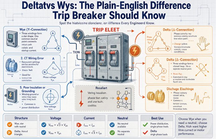
Here is the whole article in one table. If you only need the answer and not the reasoning, this is it.
| Delta | Wye (star) | |
|---|---|---|
| Voltage across each winding | full line voltage | 58 percent of line voltage |
| Line current, relative to winding current | 1.732 times winding current | equal to winding current |
| Neutral point | none in the basic connection | always present, can be grounded |
| Shape of the connection | closed loop, windings in series | three spokes meeting at a star point |
| Insulation the winding must hold | line to line | line to neutral |
| Single phase loads | only through a center tap | directly, phase to neutral |
| Third harmonic current | circulates inside the winding and heats it | adds up in the neutral |
| Typical nameplate | 480Δ, 240Δ, Dd0 | 480Y/277, 208Y/120, Dyn11 |
Read that table in one sentence: delta spends insulation to save current, wye spends current to save insulation.
That is not a metaphor. It is arithmetic, and it is the same arithmetic that makes a 500 kVA transformer a 500 kVA transformer no matter which one you pick.
A transformer does not know what a line is
This is the sentence that makes the rest of the page easy, and almost nobody says it out loud.
The core and the winding only know the voltage across the winding. A transformer has no terminal called “line voltage” inside it. It has three coils, each with a certain number of turns, each sitting in a magnetic field, and the ratio it enforces is turns primary to turns secondary on that coil.
Line voltage is what you get when you decide how to connect those coils to the outside world.
Change the connection and you change the line voltage by 1.732 without touching a single turn of copper. That is why the same winding set can be sold as a 480 volt delta unit or a 480Y/277 unit, and why a nameplate that reads 480Y/277 is telling you two voltages about the same three coils.
Why the number is 1.732 and not something else
Two voltages, equal in size, 120 degrees apart. Subtract one from the other and you are not subtracting two numbers. You are subtracting two arrows.
Put the tail of arrow B on the tip of arrow A. The gap between the start of A and the end of B is a triangle with two equal sides and a 120 degree angle between them. Close that triangle and the third side comes out at 2 × sin(60 degrees), which is 1.732 times either side.
That is the entire mystery. Not a constant someone looked up. The third side of a triangle that exists because three phases are 120 degrees apart.
Now apply it.
In delta, each winding sits directly between two line conductors. There is no subtraction to do. The winding sees exactly what the lines see, so winding voltage equals line voltage, and the line current splits between two windings, so line current is 1.732 times winding current.
In wye, each winding goes from one line to the star point. A line-to-line measurement spans two windings sitting at 120 degrees, so it does the subtraction, and it comes out 1.732 times bigger than either winding. The line current, meanwhile, has only one path, so line current equals winding current.
Same triangle, read from the other end.
The 58 percent that never makes it onto the datasheet
Flip 1.732 over and you get 0.577. A wye winding carries 57.7 percent of the line voltage across it. On a 480 volt system that is 277 volts. On 208 it is 120. On 600 it is 347. On 400 it is 231.
That 58 percent is the single most consequential number in transformer specification, and it appears on no datasheet because it is not a property of the transformer. It is a property of the connection.
The consequence is insulation. A delta winding on a 480 volt system has 480 volts across it, so the insulation system, the creepage, the clearances and the impulse withstand all have to hold 480. A wye winding on the same system holds 277, which is 58 percent of the stress for the same delivered power.
This is why, at medium voltage, you will see wye on the high side far more often than delta. At 13.8 kV the difference between a winding holding 13,800 volts and one holding 7,967 volts is not academic. It is a different insulation class, a different BIL, a different price, and a different set of clearances inside a tank that has to fit on a truck.
The winding does the same work either way
Here is where the standard “delta has more power” claim falls apart, and it is worth doing the arithmetic once because it reframes everything after it.
Take 500 kVA at 480 volts, three phase. The line current is the same in both cases because the load is the same: 601 amps. Look at what each winding is doing.
| Connection | Voltage across winding | Current in winding | kVA per winding |
|---|---|---|---|
| Delta | 480 V | 347 A | 166.7 kVA |
| Wye | 277 V | 601 A | 166.7 kVA |
480 times 347 is 166,560. 277 times 601 is 166,477. The two answers agree to within rounding, and they have to, because three windings times 166.7 kVA is 500 kVA in both cases.
The winding is doing identical work. Delta gave it more volts and fewer amps. Wye gave it fewer volts and more amps. The product is fixed because the power is fixed.
Scale it and the pattern holds:
| Rating at 480 V | Line current | Delta winding current | Wye winding current |
|---|---|---|---|
| 75 kVA | 90 A | 52 A | 90 A |
| 500 kVA | 601 A | 347 A | 601 A |
| 2,000 kVA | 2,406 A | 1,389 A | 2,406 A |
So “delta handles more power” is not a fact about delta. A delta winding carries 58 percent of the current, and a wye winding carries 58 percent of the voltage, and neither one is doing more work than the other.
What actually changes is where you spend the money.
What you pay for in copper
Delta windings run at 58 percent of line current, so the conductor can be smaller for the same kVA. Wye windings run at full line current, so the conductor has to be bigger, and the neutral, if you bring one out, is a fourth conductor that has to be sized and pulled and terminated.
That is a real material difference at 2,000 kVA. It is close to noise at 75 kVA.
What you pay for in insulation
The trade runs the other way here. Delta windings sit at full line voltage, so every turn of insulation, every spacer and every clearance in the delta winding is working harder. Wye windings sit at 58 percent, which is why the wye side of a medium voltage transformer is usually the cheaper winding to build and the easier one to fit.
Above roughly 15 kV, that insulation penalty is the reason delta starts losing. Below 600 volts, it barely registers.
Delta in plain English
Delta closes the three windings into a ring. The finish of A goes to the start of B, the finish of B to the start of C, the finish of C back to the start of A. The three line conductors come off the three corners.
There is no point in that ring where all three windings meet, which is why there is no neutral. It is not that delta refuses to give you a neutral. There is no electrically meaningful place to attach one.
What delta gives you
No neutral current to worry about. With no neutral, there is no unbalanced neutral current, no neutral to oversize, no neutral to bond in the wrong place. For a plant that is all motors, that removes a whole category of problems.
A path for third harmonic current. This one gets oversold, so here is the honest version. Third, ninth and fifteenth harmonics are in phase with each other on all three legs, so they cannot cancel. In a delta winding they have somewhere to go: they circulate around the closed loop. That keeps them out of the upstream system, which is genuinely useful. It also means they become heat inside the delta winding, and that heat is real. The harmonics do not disappear. They are converted.
A ground reference you can choose. Corner ground one corner and you have a grounded system with a defined reference. Leave it floating and you have a system that keeps running after a single ground fault. Both are legitimate designs, and both are used every day.
Survival of one open unit. In a bank of three single phase units, lose one and the other two keep delivering three phase power through an open delta. Not full power, and the number matters, which comes up later.
What delta charges you
No line-to-neutral voltage. A basic 480 volt delta gives you 480 between phases and nothing else. Every 120 volt receptacle, every control power supply, every occupancy sensor in the building needs a separate source. That single fact is why delta service is rare in commercial buildings and common in plants.
A silent first ground fault. On an ungrounded delta, the first phase-to-ground fault draws only capacitive charging current, typically a few amps. No breaker trips. No light flickers. The system keeps running, which sounds like a feature until the second fault lands on a different phase, at which point you have a phase-to-phase fault through ground with no upstream device expecting it.
Phase-to-ground voltage that floats. With no ground reference, the voltage from any phase to ground can drift anywhere up to the full line voltage. That means 480 volt insulation to ground on a 480 volt system, not 277. Surge arresters get selected on line-to-line voltage. Cable insulation gets rated on line-to-line voltage. Anyone who sizes those parts off 277 because “it’s a 480 system” has made a quiet mistake.
Circulating current if the windings disagree. In a closed delta, the three windings are in series with each other around a loop. If their ratios are not identical, the mismatch voltage drives current around that loop with nothing but winding impedance to limit it. At 5 percent impedance and a 1 percent ratio mismatch, the circulating current is about 6.7 percent of winding rating, with no load connected at all. At 5 percent mismatch it is roughly 33 percent. The unit runs hot and nobody knows why.
There is a field test for it. Open one corner of the delta, put a voltmeter across the gap, and energize. A healthy set reads close to zero. Anything above a few percent of rated voltage means the ratios disagree or a turn is shorted, and you close that corner at your own risk.
Wye in plain English
Wye joins one end of each winding at a common point and brings the other ends out to the lines. That common point is the star point, and the moment you bring it out to a terminal it becomes the neutral.
Everything wye is good at comes from that one terminal.
The neutral is the whole point
With a neutral you get two voltages from one transformer. On a 480Y/277 unit, 480 volts phase to phase runs the motors and the drives, and 277 volts phase to neutral runs the lighting. On a 208Y/120 unit, 208 runs the small three phase equipment and 120 runs everything that plugs in.
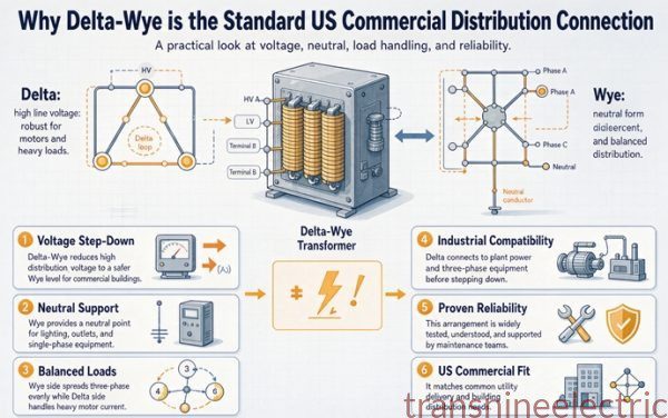
That is why the North American commercial default is a delta primary and a grounded wye secondary. The utility side wants a delta for the reasons above. The building side wants a neutral for the reasons on this page. One transformer serves both.
It also gives you a defined ground reference. Bond the neutral to ground at the transformer and you have a separately derived system with its own grounding electrode, its own bonding jumper and a stable phase-to-ground voltage. Fault current has a low impedance path back to the source, so a ground fault looks like a fault and the breaker does its job.
That bond happens at one point. One. A second bond downstream puts normal neutral current onto the grounding conductor, and every ground fault sensor between the two bonds now sees a fault that is not there.
The bill the neutral pays
The neutral is not free, and the invoice arrives as heat.
Third harmonic currents from switch mode power supplies, LED drivers and electronic ballasts are in phase on all three legs. In a wye they do not cancel in the neutral. They add. Three equal third harmonic currents of 10 amps each put 30 amps on the neutral, because the neutral carries the sum, not the difference.
Run the numbers on a real mix:
| Third harmonic, per phase | Current in the neutral |
|---|---|
| 10 percent of fundamental | 30 percent of phase current |
| 33 percent of fundamental | 99 percent of phase current |
| 50 percent of fundamental | 150 percent of phase current |
| 66 percent of fundamental | 198 percent of phase current |
A neutral sized at 100 percent of the phase conductors is at its limit when the third harmonic reaches about one third. Above that it is undersized, and the failure mode is a neutral that runs hotter than any phase conductor while every clamp meter on the phases reads normal.
This is why the code requires the neutral to be counted as a current carrying conductor where the major portion of the load is nonlinear. In the 2020 edition of the National Electrical Code that is 310.15(E), and in earlier printings it was 310.15(B)(5). Either way the instruction is the same: on a four wire wye feeding a lot of electronics, the neutral is a live conductor, and derating has to account for it.
Wye does not create this problem. Wye just gives the problem a wire to live in, which is arguably better than the alternative.
Why you rarely see wye-wye
A wye-wye transformer has no delta anywhere in it, and that turns out to matter twice.
First, third harmonic magnetizing current has nowhere to circulate. In a delta winding it can flow around the loop and the flux stays clean. In a wye-wye it distorts the flux, which distorts the output voltage waveform, which shows up as a flat topped or notched voltage that drives every connected device slightly crazy.
Second, zero sequence current has no path. On a wye-wye unit, a line-to-ground fault on the secondary sees a high zero sequence impedance, so the fault current is small and hard to distinguish from load. Ground fault protection gets difficult to set, and the fault burns longer before anything notices.
The fix is a delta tertiary, a third winding connected in delta that carries no load and exists only to let third harmonic and zero sequence current circulate. Add it and wye-wye works fine. Leave it out and you have a transformer that behaves well on paper and badly in a building full of electronics.
This is not a reason to avoid wye-wye. It is a reason to check whether the unit you are buying has the stabilizing winding, and to notice when a cheap quote quietly does not.
Four meter readings that tell you what you are standing in front of
This is the part nobody writes, and it is the part that saves an hour on site.
You walk up to an open panel. You do not have the drawings. You have a meter and a nameplate you cannot fully read. Measure phase to ground on all three legs and phase to phase across two of them, and the numbers identify the system before you touch anything.
| What the meter reads | What you are looking at |
|---|---|
| 277 to ground on all three, 480 between phases | 480Y/277 solidly grounded wye |
| 120 to ground on all three, 208 between phases | 208Y/120 solidly grounded wye |
| 120 to ground on two legs, 208 on the third, 240 between phases | 240 volt delta, center tapped, high leg on B |
| 0 on one leg, 480 on the other two | corner grounded 480 volt delta |
| Erratic, wandering between 100 and 400, never settling | ungrounded delta, no fault, and the meter is reading capacitance |
| 277 to ground everywhere but the neutral reads a few volts to ground | grounded wye with the system bonding jumper missing or loose |
That last row is the one that gets missed. A wye system whose neutral bond is open has no solid ground reference. Phase-to-ground voltages can drift anywhere between zero and the full line voltage, surge protection misbehaves, and ground fault protection either nuisance trips or never trips. It looks like a wye and it does not act like one.
The high leg and why it is 208
Center tap one winding of a 240 volt delta and ground the tap. That winding is now 120 volts from either end to the tap, and 240 end to end. Fine so far.
Now measure from the tap to the third corner, the one that is not on the center tapped winding. That corner sits at the tip of a triangle whose other two corners are 120 volts away at 120 degrees. The distance from the center of that base to the tip is 120 × 1.732, which is 208.
A 240 volt delta with a center tap therefore gives you 120, 120 and 208 to neutral. Three different line-to-neutral voltages on one system, and one of them will destroy anything expecting 120.
The high leg is phase B by convention in North America, and the code requires it to be durably marked, in orange. The reason is not tidiness. The reason is that a panel with two rows of 120 volt breakers and one row at 208 is a panel where someone will eventually land a 120 volt circuit on the wrong row and feed 208 into equipment rated for 120. It happens. It is the single most common high-leg mistake, and the orange tape exists to prevent it.
Manufacturers generally tell you to keep line-to-neutral load on a high-leg delta to a few percent of the transformer rating, because the center tapped winding is the only source of it and that winding was sized for the balanced three-phase load.
The turns ratio that looks wrong
Here is a figure that has sent people back to the shop to replace a good transformer.
Nameplate: 13,800 delta to 480Y/277, 1,000 kVA. You put a turns ratio tester on it and set the nameplate values. The tester is in single phase mode, so it compares winding to winding. It reads 49.8.
Somebody in the trailer looks up 13,800 divided by 480 and gets 28.75, and concludes the transformer is 73 percent off.
It is not. The winding ratio is 13,800 divided by 277, which is 49.8. The line ratio is 13,800 divided by 480, which is 28.75. The two differ by exactly 1.732, because the secondary is wye and the √3 lives between the winding and the line.
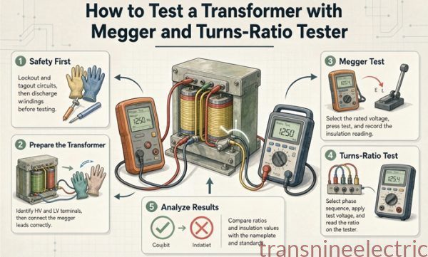
Both numbers are correct. They answer different questions. A ratio tester in single phase mode measures windings. A nameplate in three phase mode measures lines. Set the instrument to match the question you are asking, or you will condemn good hardware all afternoon.
Grounding is where the math stops being math
Up to here, delta and wye are a pair of arithmetic relationships. Grounding is where they become two different safety philosophies.
Wye, where the first fault is loud
Bond the neutral solidly and a line-to-ground fault becomes a low impedance loop from the fault, through the grounding system, back to the transformer neutral. Current flows in the thousands of amps. The breaker trips in a fraction of a second. The lights go out, someone calls an electrician, and the damage is contained.
That is the design intent. A wye system converts a hidden fault into a visible one immediately.
The magnitude is worth knowing. On a delta-wye transformer, the delta primary gives zero sequence current a place to circulate, so the zero sequence impedance on the secondary side is close to the positive sequence impedance. When those two are about equal, a bolted single line-to-ground fault draws roughly the same current as a three-phase fault. On a transformer with a lower zero sequence impedance it can draw a bit more.
Practically: if you sized the switchgear for a 30 kA three-phase fault and the unit is delta-wye, do not relax on the assumption that a ground fault will be smaller. On some units it is not.
Delta, where the first fault is silent
Leave the delta ungrounded and the first line-to-ground fault has no return path except capacitance. A few amps, sometimes less. Nothing trips. The system runs on, which is exactly why ungrounded deltas exist in the first place: a pulp mill or a hospital that cannot tolerate an unexpected shutdown will accept a faulted system running until the next maintenance window.
The price is that phase-to-ground voltage on the two healthy phases rises from 277 to 480, which is 1.732 times normal, and it stays there. Every piece of insulation in the system is now being tested at a level it was not designed for, indefinitely.
Arcing ground faults on ungrounded systems are worse. An intermittent arc can drive phase-to-ground voltage to several times nominal, and IEEE Std 142 treats that transient overvoltage as the main argument against running ungrounded for long. This is why ungrounded systems in practice get a ground fault detection scheme, either three lights, a voltmeter with a selector switch, or a pulsing current system that finds the faulted feeder. The detection is not optional decoration. It is the only thing standing between the first fault and the second one.
The code position is straightforward. Article 250 sets out which systems must be grounded and which may be left ungrounded, and a 480 volt three wire delta falls in the second group. That is why corner grounded and ungrounded 480 volt delta installations exist at all. Read 250.20 and 250.21 with your authority having jurisdiction rather than taking a blog’s word for it, including this one.
Where each connection actually ends up
Forget the theory for a minute. This is what gets specified.
| Load | Connection | Why |
|---|---|---|
| Plant full of three phase motors | delta | no neutral needed, no neutral to fail |
| Commercial building with lighting and receptacles | delta-wye, grounded wye secondary | one transformer, two voltages |
| Data hall with drives and servers | grounded wye | drives and power supplies want a neutral reference |
| Medium voltage utility distribution | delta primary | no neutral to carry over long distances |
| Generator step-up | delta on the generator side, wye on the high side | insulation economy at high voltage |
| Anything above about 15 kV | wye on the high side | 58 percent of the insulation stress |
| Older 240 volt light industrial service | center tapped delta, high leg on B | gives 120 for a few receptacles without a second transformer |
| Temporary or emergency bank of three single phase units | delta or open delta | survives losing one unit |
One row deserves a note: the generator step-up case. A generator producing 480 or 600 volts has no reason to be wye, and the transmission side at 115 or 230 kV has every reason to be. That is why large step-up units are almost always delta on the low side and wye on the high side, and why the reverse arrangement shows up in step-down substations.
The replacement trap
Now the part that costs money.
Two transformers. Same kVA. Same nameplate voltages. Same impedance to two decimal places. One is Dyn11 and one is Dyn1. Put the second one where the first one was and it will run fine on its own, right up until someone closes the tie breaker.
Thirty degrees and 4.3 times rated current
Delta-wye introduces a 30 degree phase displacement between primary and secondary. It is invisible to every load in the building, because loads do not care about absolute phase, only about the relationship among the three phases they receive.
It is not invisible when two sources meet.
Connect two transformers whose secondaries are 30 degrees apart, and the voltage difference between corresponding phases is 2 × sin(15 degrees), which is 0.518 per unit. That difference drives current through the two transformer impedances in series. At 5.75 percent impedance each, the loop impedance is 0.115 per unit and the circulating current is 0.518 divided by 0.115, which is 4.5 per unit.
Four and a half times rated current, before any load is connected.
Nothing survives that. The protection operates, someone reports a fault, and the actual cause is a clock number on a nameplate that nobody read.
The clock number is the hour position of the low voltage phasor relative to the high voltage phasor, and each hour is 30 degrees. Dyn11 sits at 11 o’clock and Dyn1 at 1 o’clock, and they are 60 degrees apart, not 30. Whether you call 11 o’clock leading or lagging depends on which convention the drawing in front of you uses, and two competent engineers have argued about that for a century. What matters in the field is simpler: if the clock numbers differ, the secondaries do not line up, and you do not close the tie.
The constructive use of the same fact is the twelve pulse rectifier: one delta secondary and one wye secondary on the same core, 30 degrees apart, and the fifth and seventh harmonics cancel in the DC output. Same physics, opposite intent.
Six things people get wrong
| The claim | What is actually true |
|---|---|
| Delta gives you more power from the same frame | The winding does identical work. Delta trades current for voltage, wye trades voltage for current, the kVA is the same |
| Wye is safer than delta | Safety comes from grounding, not from the connection. A corner grounded delta is grounded and an ungrounded wye is not |
| You cannot get 120 volts out of a delta | You can, from a center tapped winding. That is the high leg arrangement, and it comes with a 208 volt trap |
| A delta traps harmonics so they disappear | They circulate in the delta winding and heat it. Trapped is accurate, gone is not |
| You can reconnect a delta unit as wye in the field | Almost never. The winding insulation, the lead arrangement and the nameplate all have to agree, and usually they do not |
| Same kVA and same voltage means interchangeable | Only if the vector group matches too. A 30 degree difference is 4.5 times rated current the moment you parallel |
FAQ
Is delta better than wye?
Neither is better in general, and the claim that one is comes from comparing on the wrong axis. At the same kVA and line voltage the winding does identical work: at 500 kVA and 480 volts the delta winding carries 480 volts at 347 amps and the wye winding carries 277 volts at 601 amps, and both come to 166.7 kVA. Delta wins on conductor size and loses on insulation. Wye wins on the neutral and loses on neutral current.
Why is line voltage 1.732 times phase voltage in a wye connection?
Because a line-to-line measurement spans two windings that sit 120 degrees apart, and subtracting two equal phasors 120 degrees apart gives a difference of 2 times sin(60 degrees), which is 1.732 times either one. In delta each winding sits directly between two lines, so there is nothing to subtract and the two voltages are equal. The 1.732 is not a constant anyone chose. It is the third side of a triangle.
Can I get 120 volts from a delta transformer?
Yes, from a center tapped winding. Center tap one winding of a 240 volt delta, ground the tap, and you get 120 volts from either end of that winding to the tap. The trap is the third corner, which sits 208 volts from the tap because 120 times 1.732 is 208. That corner is the high leg, it is phase B by convention, and it must be marked, normally with orange, so nobody lands a 120 volt circuit on it.
Why does my 480 volt delta read 480 to ground on two phases and zero on the third?
You are on a corner grounded delta. One corner of the delta is solidly grounded, so that phase reads zero to ground by definition and the other two read the full 480 volts to ground. It is a legal and deliberate configuration, not a fault. Do not assume it is ungrounded and start hunting for a ground fault, and do not assume the phase that reads zero is dead, because it is a live conductor held at ground potential.
What is a high leg and why is it 208 volts?
It is the third corner of a center tapped delta. Two corners sit 120 volts from the tap and the third sits at the tip of a triangle whose base is 240 volts wide, so its distance from the tap is 120 times 1.732, or 208. You end up with 120, 120 and 208 to neutral on one system. Keep line-to-neutral load on a high leg delta to a few percent of the transformer rating, because the center tapped winding is the only source of it.
Why does the neutral get hot on a wye system full of computers?
Third harmonic currents from switch mode supplies are in phase on all three legs, so they add in the neutral instead of cancelling. Three 10 amp third harmonics put 30 amps on the neutral. A neutral at 100 percent of phase ampacity is at its limit once the third harmonic reaches about one third of the fundamental, and the code counts it as a current carrying conductor. Clamp the neutral and compare it to the phases.
Can I parallel a Dyn1 and a Dyn11 transformer?
Only if you want 4.5 times rated current with no load connected. The two clock numbers put the secondaries 60 degrees apart, and the voltage difference between corresponding phases drives circulating current limited only by the two impedances in series. At 5.75 percent each, 0.518 divided by 0.115 is 4.5 per unit. Matching kVA, voltage, impedance and tap position is not enough.
How much capacity is left in an open delta bank?
Two units of a three unit bank deliver 57.7 percent of the original bank rating, because capacity is 1.732 times the rating of one unit rather than 2 times. Three 167 kVA units make a 500 kVA bank, and two of them make 289 kVA. That is 57.7 percent of the bank, but 86.6 percent of the 334 kVA you actually installed. Which figure is right depends on the baseline, and that distinction gets lost in most write-ups.
Why does a wye-wye transformer need a delta tertiary?
Because a wye-wye has no closed loop for third harmonic magnetizing current to circulate in, and no low impedance path for zero sequence current. The first distorts the flux and the output voltage waveform. The second makes line-to-ground faults hard to detect, because the fault current is small. A delta tertiary, or a buried stabilizing winding, gives both currents somewhere to go. Ask whether your quote has one.
Does a delta connection give more power than a wye?
No. The winding does identical work in both. At 480 volts and 500 kVA the delta winding carries 480 volts at 347 amps, the wye winding 277 volts at 601 amps, and each is 166.7 kVA. Delta carries 58 percent of the line current, which lets the conductor be smaller, and wye carries 58 percent of the line voltage, which lets the insulation be lighter. The power is fixed by the core and the copper, not by the connection.
What turns ratio should a tester read on a 13,800 to 480Y/277 unit?
49.8 in single phase mode, and 28.75 in three phase line-to-line mode. The winding ratio is 13,800 divided by 277, which is 49.8. The line ratio is 13,800 divided by 480, which is 28.75. The two differ by exactly 1.732 because the secondary is wye. Both readings are correct, and confusing them condemns good transformers every week.
Why does an ungrounded delta not trip on the first ground fault?
Because there is no return path. The only current is capacitive charging current, typically a few amps, which no overcurrent device is set to see. The system keeps running, but phase-to-ground voltage on the two healthy phases rises to the full line voltage and stays there, so every insulation system in the plant is tested at 1.732 times its normal stress. That is why these systems need ground fault detection in practice.