Every transformer sizing calculator on the internet does the same thing. You type in a load, it multiplies by a couple of factors, and it hands you a kVA number and two currents. Then it stops.
That is where your real decisions start, not where they end. The kVA number you get out of a calculator is a rounding target, and the rounding target is only useful once you know which ratings actually exist, what the step up costs you in switchgear and cable, and whether the size you picked has a federal efficiency row behind it or has to be interpolated.
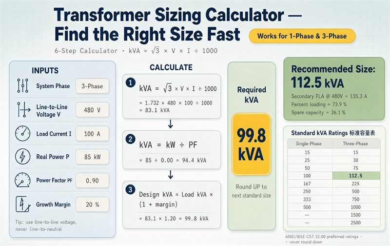
This page is the calculator plus everything after it. Six steps, every standard rating in the ladder with its current and its loss budget, and the downstream check that decides whether your size fits in the room.
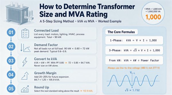
For the reasoning behind capacity selection, our guide to determining transformer size and MVA rating covers the method in more depth. This page is the executable version.
The answer in one line
Take your connected load in kVA, multiply by a demand factor, multiply by one plus your growth allowance, divide by your target loading, then round up to the next rating that actually appears in the standard list.
Written out:
Required kVA = (connected kVA x demand factor x (1 + growth)) / target loading
Then round up. What “round up” means is the part most calculators get wrong, and we will get to it.
The six inputs, and which ones actually matter
| Input | Typical range | What happens if you get it wrong |
| Connected load, kVA | Measured or from the load schedule | Everything downstream scales with it |
| Power factor | 0.80 to 0.95 | Off by 0.1 and you are off by about 11% on the kVA |
| Demand factor | 0.40 to 1.00 | The single widest error bar in the whole calculation |
| Growth allowance | 0% to 50% | Usually absorbed by the ladder, sometimes costs a full step |
| Target loading | 0.75 to 0.90 | Divides straight into the answer |
| Site derating (heat, altitude, harmonics) | 0% to 20% | Pushes you over a step boundary at the margin |
Two of these are measured. Four are judgement calls. A calculator that asks for all six with equal confidence is hiding the fact that one of them, the demand factor, can swing the answer by two full ratings while the other three combined might not move it at all.
Step 1: Get the load into kVA, not kW
Transformers are rated in apparent power. The windings carry current regardless of how much of it does useful work, so a load that draws 100 kW at 0.8 power factor pulls 125 kVA through the transformer, and 125 kVA is what you are buying.
Three conversions cover nearly everything:
From kW: kVA = kW / power factor
From three-phase amps: kVA = (sqrt(3) x V x A) / 1000
From single-phase amps: kVA = (V x A) / 1000
For motor nameplates given in horsepower, convert to kW first (1 hp = 0.746 kW) and then divide by both motor efficiency and power factor. A 100 hp motor at 94% efficiency and 0.85 power factor draws 100 x 0.746 / (0.94 x 0.85) = 93.4 kVA, not 74.6 kVA. Skipping efficiency is a 25% error on every motor in the schedule.
One more thing about power factor correction. Capacitors on the low-voltage bus fix the power factor the utility sees. They do not change what the transformer secondary carries, because the capacitors are downstream of it. Sizing the transformer smaller because you have PFC is a real and common mistake.
Step 2: Demand factor is the input with the widest error bar
Not every load runs at once. The demand factor scales the connected total down to something like the real peak.
NEC Article 220 sets out demand factors by occupancy, and several of the published calculators cite specific clauses. The commercial general lighting method in 220.42 puts the first 12.5 kVA at 100% and the remainder at 50%. The dwelling optional methods in 220.82 and 220.83 put the first 10 kVA at 100% and the remainder at 50%. For five or more clothes dryers, Table 220.54 starts at 80% for five and drops to 35% for forty. Heating and air conditioning are each taken at 100% of nameplate, but 220.60 lets you count only the larger of the two, since they do not run together.
Check those clauses against the edition your AHJ enforces before you rely on the numbers. The point that survives any edition is this one:
| Occupancy | Typical demand factor |
| Continuous process plant | 0.85 to 1.00 |
| Data centre | 0.85 to 0.95 |
| Light manufacturing | 0.70 to 0.80 |
| Office | 0.60 to 0.80 |
| School | 0.50 to 0.70 |
| Hospital | 0.40 to 0.60 |
| Residential dwelling | 0.40 to 0.65 |
Watch what that range does. Take a 400 kW office load at 0.90 power factor with 25% growth and an 80% target loading. At a 0.70 demand factor the required size is 486 kVA, so you buy 500 kVA. At a demand factor of 1.0, the same building needs 694 kVA, so you buy 750 kVA. One input, two full ratings apart, and no calculator can tell you which end of that range you are on.
If you have twelve months of utility interval data or a recording meter on the existing service, use the measured peak instead. It beats any table.
Step 3: Growth and loading margin pull in opposite directions
Growth allowance pushes the number up. Target loading pushes it up as well, because dividing by 0.80 means you are specifying a machine that runs at 80% of its nameplate. That is not double counting, and it is worth being clear about why.
The growth allowance covers load you expect to add. The loading margin covers the fact that a transformer running at 100% of nameplate continuously runs hot, ages faster, and has no room for a motor start or a hot week. They are different risks, so both belong in the calculation.
But they can cancel, and that is worth checking on your own numbers. A demand factor of 0.80 with 25% growth multiplies out to 0.80 x 1.25 = 1.00. Those two corrections do nothing at all together. If you set them that way by habit, you have not applied either one.
Here is the same office building under three sets of assumptions:
| Assumptions | Connected | Demand | Design | Required | Rating |
| DF 0.70, growth 25%, load 80% | 444 kVA | 311 kVA | 389 kVA | 486 kVA | 500 |
| DF 1.00, growth 25%, load 80% | 444 kVA | 444 kVA | 556 kVA | 694 kVA | 750 |
| DF 0.70, growth 0%, load 80% | 444 kVA | 311 kVA | 311 kVA | 389 kVA | 500 |
Row 1 and row 3 land on the same rating. Twenty five percent of growth was free, because 389 kVA and 486 kVA both round up to 500. Row 2 costs two steps. The growth allowance did not cause that, the demand factor did.
That absorption effect is the single most useful thing to know about this calculation, and no online calculator shows it to you.
Step 4: Where the standard ratings actually come from
This is the step where the calculators disagree with each other, and where the disagreement is resolvable.
The standard kVA ratings for distribution transformers in the United States are published in the Federal Register of November 12, 1998, at 63 FR 63360, in Table 2 for liquid-immersed units and Table 3 for dry-type units. The Department of Energy reproduced them there and stated in the same notice that these are the preferred ratings from ANSI/IEEE C57.12.00-1993 for liquid-immersed transformers and ANSI/IEEE C57.12.01-1989 for dry-type transformers.
Here they are, in full.
Liquid-immersed, Table 2
| Phase | Ratings, kVA |
| Single-phase | 10, 15, 25, 37.5, 50, 75, 100, 167, 250, 333, 500, 667, 833 |
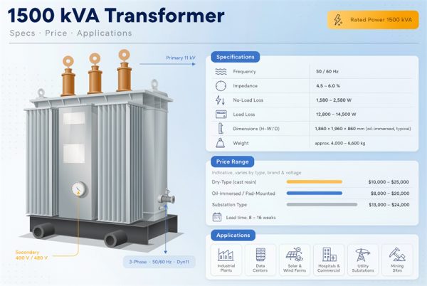
| Three-phase | 15, 30, 45, 75, 112.5, 150, 225, 300, 500, 750, 1000, 1500, 2000, 2500 |
Dry-type, Table 3
| Phase | Ratings, kVA |
| Single-phase | 15, 25, 37.5, 50, 75, 100, 167, 250, 333, 500, 667, 833 |
| Three-phase | 15, 30, 45, 75, 112.5, 150, 225, 300, 500, 750, 1000, 1500, 2000, 2500 |
Note what is not there. There is no 200 kVA. There is no 3000 kVA. There is no 3, 5, 6, 7.5 or 9 kVA, and the smallest three-phase rating is 15. The three-phase ladder stops at 2500 kVA in these tables.
Now compare that against what the calculators tell you:
| Calculator | Published list | Problem |
| volt.webtech360 | 3, 6, 9, 15, 30, 45, 75, 112.5, 150, 225, 300, 500, 750, 1000, 1500, 2000, 2500 | 3, 6 and 9 are not in either table, and they sit below the coverage floor in 10 CFR 431.192, which starts at 10 kVA for liquid and 15 kVA for dry |
| tradecalc.org | 3, 5, 7.5, 10, 15, 25, 30, 37.5, 45, 50, 75, 100, 112.5, 150, 200, 225, 250, 300, 500, 750, 1000 | 200 kVA is not a standard rating. The three-phase ladder goes 150 to 225, and the single-phase ladder goes 167 to 250 |
| pe-calc.com | 15, 30, 45, 75, 112.5, 150, 225, 300, 500, 750, 1000, 1500, 2000, 2500, 3000, 5000 | 3000 kVA is not in the list. Also credits the sizes to ANSI C57.12.10, while the Federal Register notice credits C57.12.00 and C57.12.01 |
| mepbase.com | …1500, 2000, 2500, 3750, 5000, 7500, 10000 | 7500 and 10000 kVA are above the scope of 431.192, which covers liquid-immersed units from 10 to 5,000 kVA and dry-type from 15 to 5,000 kVA |
| engineersuniverse | three-phase: 45, 75, 112.5, 150, 225, 300… | Omits 15 and 30. A 20 kVA requirement gets sent to 45 when 30 is the correct answer |
None of these are typos in the ordinary sense. They come from people merging the single-phase and three-phase columns into one list, or extending the ladder past where the tables stop. If you use one of them, you can end up specifying a rating nobody stocks.
And that matters more than lead time. A rating with no row in the federal efficiency table has to be interpolated, and the regulation says so explicitly. That is the first reason to stay on the ladder, ahead of availability and ahead of price.
Step 5: Single-phase or three-phase changes the answer twice
Most calculators ask you to pick a phase and then size against one list. The catch is that the same arithmetic gives opposite answers depending on which list you are looking at.
Say your calculation produces 100 kVA.
Against the liquid-immersed single-phase list, 100 is right there. You buy a 100 kVA transformer.
Against the three-phase list, 100 does not exist. The ladder goes 75, then 112.5. You buy 112.5 kVA.
Now say it produces 150 kVA. The three-phase list has 150. The single-phase list jumps from 100 to 167, so a single-phase answer is 167 kVA.
100 kVA: standard single-phase, non-standard three-phase. 150 kVA: standard three-phase, non-standard single-phase.
There is a quick way to check. Divide a three-phase rating by three and see whether the result lands on a single-phase rating. 150 / 3 = 50, which is on the single-phase list, so 150 is standard three-phase. 300 / 3 = 100, also on the list. 750 / 3 = 250, on the list.
The shortcut breaks above 300 kVA. 167 x 3 = 501, and the three-phase ladder reads 500, not 501. 333 x 3 = 999, and the ladder reads 1000. Above 300 kVA, go back to the table instead of dividing.
It breaks completely at 1000 kVA. 1000 / 3 = 333.33, which is not 333, and the single-phase ladder caps at 833. So a 1000 kVA single-phase requirement has no answer at all, and dropping to 833 gives you 17% less than you asked for. If your arithmetic says 1000 kVA and you were planning single-phase, you are specifying three-phase.
Our single-phase transformer guide covers where single-phase still makes sense. Above roughly 167 kVA it usually does not, and the currents in the table below show why. A 333 kVA single-phase unit at 240 V draws 1,388 A and needs four runs of 1000 kcmil per phase. That is a busway job dressed up as a transformer.
Step 6: Round up, and check what the step costs you
The ladder is not evenly spaced. Going up one step buys very different amounts of headroom depending on where you are standing.
| Step | Increase | Step | Increase |
| 15 to 30 | +100% | 225 to 300 | +33% |
| 45 to 75 | +67% | 750 to 1000 | +33% |
| 300 to 500 | +67% | 112.5 to 150 | +33% |
| 500 to 750 | +50% | 1500 to 2000 | +33% |
| 1000 to 1500 | +50% | 2000 to 2500 | +25% |
| 150 to 225 | +50% |
At the bottom of the ladder one step doubles your capacity. At the top it adds a quarter. If you are sitting at 1,020 kVA and your growth case puts you at 1,400 kVA in five years, the 1500 kVA rating costs you one step and puts you at 71% loading today. If you are at 1,020 and buy 1000 kVA because it is closer, you are at 102% the day the expansion lands.
The practical version of this: run your calculation, then run it again with your realistic five year load, and see whether both answers fall inside the same step. If they do, buy the step. If they do not, buy the step that covers the second number.
The federal efficiency floor for every standard rating
Once your rating is on the ladder, it has a row in 10 CFR 431.196. The values below are the current liquid-immersed three-phase floors, measured at 50% of nameplate load, and the allowed loss is what that efficiency works out to in watts at the test point.
Allowed loss = (kVA x 1000 x 0.5) x (1 / efficiency – 1)
| Rating, kVA | Floor, % | Allowed loss, W | FLA at 480 V | Device, A | Copper per phase | Fault current, kA |
| 15 | 98.65 | 103 | 18 | 25 | 1 x 1000 kcmil | 0.4 to 1.8 |
| 30 | 98.83 | 178 | 36 | 50 | 1 x 1000 kcmil | 0.8 to 3.6 |
| 45 | 98.92 | 246 | 54 | 70 | 1 x 1000 kcmil | 1.2 to 5.4 |
| 75 | 99.03 | 367 | 90 | 125 | 1 x 1000 kcmil | 1.8 to 9.0 |
| 112.5 | 99.11 | 505 | 135 | 175 | 1 x 1000 kcmil | 2.3 to 11.3 |
| 150 | 99.16 | 635 | 180 | 250 | 1 x 1000 kcmil | 3.0 to 15.0 |
| 225 | 99.23 | 873 | 271 | 350 | 1 x 1000 kcmil | 4.5 to 22.6 |
| 300 | 99.27 | 1,103 | 361 | 500 | 1 x 1000 kcmil | 6.0 to 30.1 |
| 500 | 99.35 | 1,636 | 601 | 800 | 2 x 1000 kcmil | 8.6 to 40.1 |
| 750 | 99.40 | 2,264 | 902 | 1,200 | 3 x 1000 kcmil | 12.0 to 18.0 |
| 1000 | 99.43 | 2,866 | 1,203 | 1,600 | 3 x 1000 kcmil | 16.0 to 24.1 |
| 1500 | 99.48 | 3,920 | 1,804 | 2,500 | 5 x 1000 kcmil | 24.1 to 36.1 |
| 2000 | 99.51 | 4,924 | 2,406 | 4,000 | 8 x 1000 kcmil | 32.1 to 48.1 |
| 2500 | 99.53 | 5,903 | 3,007 | 4,000 | 8 x 1000 kcmil | 40.1 to 60.1 |
Single-phase, same source and same test point:
| Rating, kVA | Floor, % | Allowed loss, W | FLA at 240 V | Device, A | Copper per phase | Fault current, kA |
| 10 | 98.70 | 66 | 42 | 60 | 1 x 1000 kcmil | 0.9 to 4.2 |
| 15 | 98.82 | 90 | 63 | 80 | 1 x 1000 kcmil | 1.4 to 6.2 |
| 25 | 98.95 | 133 | 104 | 150 | 1 x 1000 kcmil | 2.3 to 10.4 |
| 37.5 | 99.05 | 180 | 156 | 200 | 1 x 1000 kcmil | 3.5 to 15.6 |
| 50 | 99.11 | 225 | 208 | 300 | 1 x 1000 kcmil | 4.6 to 13.9 |
| 75 | 99.19 | 306 | 313 | 400 | 1 x 1000 kcmil | 6.9 to 20.8 |
| 100 | 99.25 | 378 | 417 | 600 | 2 x 1000 kcmil | 9.3 to 27.8 |
| 167 | 99.33 | 563 | 696 | 1,000 | 2 x 1000 kcmil | 15.5 to 46.4 |
| 250 | 99.39 | 767 | 1,042 | 1,600 | 3 x 1000 kcmil | 17.4 to 69.4 |
| 333 | 99.43 | 955 | 1,388 | 2,000 | 4 x 1000 kcmil | 23.1 to 92.5 |
| 500 | 99.49 | 1,282 | 2,083 | 3,000 | 6 x 1000 kcmil | 29.8 to 138.9 |
| 667 | 99.52 | 1,609 | 2,779 | 4,000 | 8 x 1000 kcmil | 37.1 to 55.6 |
| 833 | 99.55 | 1,883 | 3,471 | 5,000 | 10 x 1000 kcmil | 46.3 to 69.4 |
Two uses for those loss columns. First, they are a floor, so any quote claiming less loss than the number shown is either quoting a different test condition or is wrong. Second, once you have guaranteed no-load and load loss in watts from a vendor, you can compare two quotes on a 30 year basis rather than on purchase price, and that comparison usually dwarfs the price difference.
What the size does to everything downstream
The kVA number sets the full load current, the current sets the overcurrent device, the device sets the conductor size, and the conductor count sets whether the job is cables or busway. Here is the three-phase ladder at the four common secondary voltages.
| Rating, kVA | 208 V | 240 V | 480 V | 600 V |
| 15 | 42 | 36 | 18 | 14 |
| 30 | 83 | 72 | 36 | 29 |
| 45 | 125 | 108 | 54 | 43 |
| 75 | 208 | 180 | 90 | 72 |
| 112.5 | 312 | 271 | 135 | 108 |
| 150 | 416 | 361 | 180 | 144 |
| 225 | 625 | 541 | 271 | 217 |
| 300 | 833 | 722 | 361 | 289 |
| 500 | 1,388 | 1,203 | 601 | 481 |
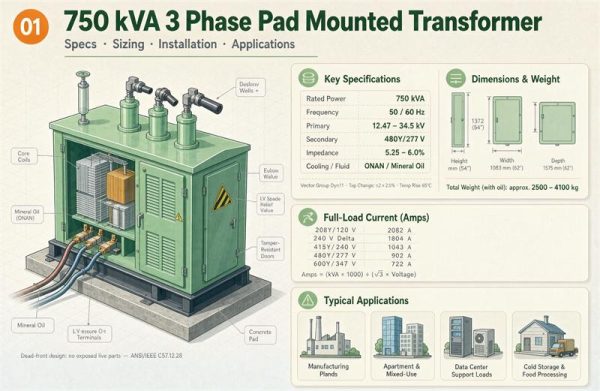
| 750 | 2,082 | 1,804 | 902 | 722 |
| 1000 | 2,776 | 2,406 | 1,203 | 962 |
| 1500 | 4,164 | 3,608 | 1,804 | 1,443 |
| 2000 | 5,551 | 4,811 | 2,406 | 1,925 |
| 2500 | 6,939 | 6,014 | 3,007 | 2,406 |
Look at what the secondary voltage does. A 750 kVA unit draws 902 A at 480 V and 2,082 A at 208 V. That is the same transformer, and the second one needs more than twice the copper, a device more than twice as large, and a very different terminating arrangement. The secondary voltage you commit to changes the project cost more than the rating does.
Three rules turn those currents into hardware.
The device. NEC 450.3 sets the overcurrent protection as a percentage of full load current, and for transformers 600 V and below with both primary and secondary protection the secondary device can go to 125%. Then NEC 240.6(A) tells you which device ratings exist. After 800 the standard sizes are 1000, 1200, 1600, 2000, 2500, 3000, 4000, 5000 and 6000. There is no 900, no 1400 and no 1800.
The conductor. NEC 215.2 and 230.42 require 125% of the continuous load for conductor ampacity. Separately, NEC 240.4(C) says that above 800 A the device rating cannot exceed the conductor ampacity, which means the next-size-up allowance disappears exactly where conductors get expensive. So the conductor has to carry the device rating, not just the load.
The count. At 75 °C copper, 1000 kcmil carries 545 A. Divide the device rating by that and round up.
Work the 2000 kVA row as an example. At 480 V the current is 2,406 A. Times 1.25 gives 3,007 A. The next standard device above 3,007 is 4,000 A, because 3,000 A is seven amps short. Seven amps. The conductors then have to carry 4,000 A, which is eight runs of 1000 kcmil per phase.
And 2500 kVA at 480 V draws 3,007 A, times 1.25 is 3,759 A, which also lands on a 4,000 A device and the same eight runs per phase. The step from 2000 to 2500 kVA costs nothing extra in the secondary switchgear or the secondary cable. Both sit on the same 4,000 A device. If your growth case lands anywhere in that band, the extra 500 kVA is free downstream.
The primary side is small, and that is when it goes wrong
The primary current is a fraction of the secondary current, so it gets less attention than it deserves. On a 750 kVA unit fed at 12,470 V the primary draws 35 A. Nobody loses sleep over 35 A.
Two things go wrong there anyway.
The first is arithmetic. For a grounded wye primary written as 12,470GY/7200, the 12,470 is the line-to-line voltage and the 7,200 is the voltage across each winding. Both give the same line current, but only if you pair them with the right formula:
I = kVA x 1000 / (sqrt(3) x line voltage) = kVA x 1000 / (3 x winding voltage)
Put 7,200 into the first version and you get 60 A instead of 35 A, which is high by a factor of 1.73. That number then goes onto the submittal, the fuse sizing and the cable schedule. It is one of the most common errors on a transformer drawing, and it is invisible unless somebody recomputes it.
The second is protection. Primary overcurrent protection for a transformer with a primary above 600 V has its own table in NEC 450.3, and the allowable percentage depends on whether secondary protection is present and on the device type. Use that table rather than a rule of thumb, and check it against the utility’s own requirements, because on a utility-served transformer the utility usually specifies the primary protection.
At 750 kVA the primary currents work out like this, computed on line voltage:
| Primary, V | Current, A | Primary, V | Current, A |
| 4,160 | 104 | 13,800 | 31 |
| 7,200 | 60 | 14,400 | 30 |
| 12,470 | 35 | 19,920 | 22 |
| 13,200 | 33 | 34,500 | 13 |
The currents are small enough that primary cable is rarely the constraint. The voltage class is the constraint, because primary BIL, terminations, surge arresters and working clearances all follow it. A 34.5 kV primary on a site that only has 13.8 kV gear is an expensive discovery.
The 22 kA switchgear test
Available fault current at the secondary is approximately the full load current divided by the impedance, expressed as a decimal. Standard low-voltage switchgear is commonly rated 22 kA, and above that you are buying 42 kA or 65 kA equipment.
The impedance is not a free variable. The definition of a special-impedance transformer in 10 CFR 431.192 carries a table of normal impedance ranges by rating, and being outside that range changes the regulatory status of the unit. So the question is whether 22 kA is reachable at all inside the normal band.
| Rating, kVA | Normal impedance band | To stay under 22 kA at 480 V |
| 150 | 1.2 to 6.0% | Any impedance in the band works |
| 225 | 1.2 to 6.0% | Needs 1.23% or higher |
| 300 | 1.2 to 6.0% | Needs 1.64% or higher |
| 500 | 1.5 to 7.0% | Needs 2.73% or higher |
| 750 | 5.0 to 7.5% | Any impedance in the band works |
| 1000 | 5.0 to 7.5% | Needs 5.47% or higher |
| 1500 | 5.0 to 7.5% | Not reachable, needs 8.20% |
| 2000 | 5.0 to 7.5% | Not reachable, needs 10.93% |
| 2500 | 5.0 to 7.5% | Not reachable, needs 13.67% |
Two readings matter. At 750 kVA you are safe across the whole band, which makes it the last three-phase rating where a 480 V secondary reliably stays inside 22 kA gear. At 1500 kVA and above you cannot get there without going outside the normal impedance band, and doing that turns the unit into a special-impedance transformer.
Note also that the ratings from 225 to 500 kVA sit in a band whose low end is 1.2% to 1.5%. A standard off-the-shelf unit at the bottom of its band will produce far more fault current than one at the top. If you are specifying in that range, put the impedance on the drawing with a tolerance, and check it against your fault study before the gear is ordered.
At 208 V none of this helps. A 750 kVA unit at 208 V produces between 27.8 and 41.6 kA across its band. Everything from 750 kVA up is over 22 kA at 208 V, which is one more reason the 480 V decision matters so much.
Peak efficiency is a number you can calculate
Several calculators tell you transformers are most efficient somewhere between 50% and 80% load. That range is wide enough to be useless, and the real answer is on the nameplate data.
Efficiency peaks where the constant no-load loss equals the load loss, and load loss scales with the square of the load. So:
Peak loading = sqrt(no-load loss / load loss at full load)
| No-load loss | Load loss at full load | Peak efficiency at |
| 400 W | 3,000 W | 37% |
| 800 W | 6,000 W | 37% |
| 1,000 W | 5,000 W | 45% |
| 1,400 W | 9,000 W | 39% |
| 2,000 W | 12,000 W | 41% |
| 2,600 W | 20,000 W | 36% |
Every one of those lands below 50%. The practical consequence is that a transformer sized for 80% target loading spends most of its life above its peak efficiency point, which is fine, because you sized it for insulation life and headroom rather than for the efficiency maximum. What you should not do is size it to hit the efficiency peak, because that puts you near full load continuously.
Ask for both loss figures in watts with a reference temperature. If a vendor will only quote an efficiency percentage, ask which load point it is measured at. The federal test point is 50% of nameplate for liquid-immersed units and 35% for low-voltage dry-type, so a percentage without a load point is not comparable to anything.
Heat, altitude, and harmonics
These three are real, and they are also where the published calculators are least reliable, because the coefficients float around the internet without sources attached.
Ambient temperature. Standard ratings assume a 30 °C average ambient with a 40 °C maximum. Above that, usable capacity drops. How fast it drops depends on the cooling class and the insulation system, so ask the manufacturer for the derating curve for the specific model rather than applying a rule of thumb.
Altitude. IEEE C57.96 and IEC 60076-12 both give methods, and they do not give the same numbers. The correction also differs between natural convection and forced air cooling, and between liquid-immersed and dry-type. Get it from the manufacturer for your site elevation.
Harmonics. Nonlinear loads like variable frequency drives, UPS systems, LED drivers and rectifiers draw distorted current, and the harmonics heat the windings beyond what the RMS current suggests. Once nonlinear content passes roughly 15% to 20% of the total, the usual answer is a K-factor rated transformer rather than an oversized standard one. Oversizing a standard unit buys you copper that does not address eddy current heating in the way a K-rated design does.
Motor starting. A motor started across the line can pull six times its running current for a second or two. The transformer has to ride through that without dropping the bus voltage far enough to trip contactors and drives. As a screening rule, if your largest motor is more than 10% to 15% of the transformer rating, check the starting voltage drop. Soft starters and VFDs change the picture entirely, so the answer depends on the starting method, not just the motor size.
Three worked examples, start to finish
Small retail, 85 kW. At 0.85 power factor that is 100 kVA connected. A 0.80 demand factor gives 80 kVA, 20% growth gives 96 kVA, and dividing by 0.80 target loading gives 120 kVA. The three-phase ladder reads 112.5 then 150, so you buy 150 kVA. Full load current at 480 V is 180 A, the device is 250 A, and one run of 250 kcmil per phase carries it.
Light manufacturing, 500 kW. At 0.85 power factor that is 588 kVA connected. At 0.80 demand, 471 kVA. With 25% growth, 588 kVA. Divided by 0.80, 735 kVA, which rounds to 750 kVA. At 480 V that is 902 A, a 1,200 A device, and three runs of 1000 kcmil per phase. Across the 5.0% to 7.5% impedance band the fault current runs 12.0 to 18.0 kA, so 22 kA gear is fine and you do not need to specify impedance to hold the line.
Data hall, 800 kW. At 0.95 power factor that is 842 kVA connected. At 0.90 demand, 758 kVA. With 40% growth, 1,061 kVA. Divided by 0.80, 1,326 kVA, which rounds to 1500 kVA. At 480 V that is 1,804 A, a 2,500 A device, five runs of 1000 kcmil per phase, and fault current between 24.1 and 36.1 kA. Plan on 42 kA or 65 kA gear, because no impedance inside the normal band gets you under 22 kA.
Notice that the third example buys 1,326 kVA of requirement and takes 1,500. The extra 174 kVA is what the ladder hands you, and it is the reason the loading sits at 71% rather than 88%.
Running it backwards: is the transformer you have big enough
Half the sizing questions that reach us are not about new units. Somebody has a transformer already and wants to add a load to it. The same arithmetic works in reverse, and it takes about ten minutes with a clamp meter.
Step 1. Get the full load current from the nameplate. Take the rated kVA and the secondary voltage and compute it, or read it off the nameplate if it is printed there. A 500 kVA unit at 480 V is 601 A.
Step 2. Measure the actual current on each phase. Clamp each phase at the secondary, at the busiest time you can catch. Do not average the three.
Step 3. Loading is the highest phase current divided by full load current. If your 500 kVA unit reads 580 A, 470 A and 505 A, the loading is 580 / 601 = 96%, not (580 + 470 + 505) / 3 / 601 = 87%. The highest phase is the one that sets the temperature, and it is the one that matters.
Step 4. Headroom is the difference. At 601 A full load with an 80% target, the unit should sit near 481 A. If the highest phase is at 580 A, you have roughly 21 A of headroom at that target, which is about 17 kVA at 480 V three-phase. That is the honest answer, and it is usually much smaller than people expect.
Unbalance is the part that surprises people. If a three-phase transformer carries 50 kVA on phase A, 40 on phase B and 30 on phase C, the total is 120 kVA but the sizing answer is 50 x 3 = 150 kVA, because the transformer has to be rated for the worst phase carried on all three. Distributing single-phase loads evenly across the phases is free capacity, and it is the cheapest correction available on an existing installation.
If the answer is that you are full, the options are redistribute the single-phase loads, add a second unit on a separate bus, or step up one rating. The second option has a fault current benefit as well, but only if the two secondaries feed separate buses. Two units on a common bus still see roughly the same fault current as one unit of the combined rating, because the impedance is in parallel only when the sources are separate.
What to send a supplier once you have a number
The kVA is the opening line of the specification, not the whole thing. A useful request for quote contains:
- Rating, phase, frequency, and confirmation that the rating is on the standard list.
- Primary and secondary voltages, vector group, and whether the primary is grounded wye.
- Impedance with a tolerance, and confirmation it sits inside the normal band unless you intend otherwise.
- Guaranteed no-load loss and load loss in watts, at a stated reference temperature, plus the routine test report.
- Which paragraph and test load the efficiency claim is made against.
- Cooling class, tap range, tap changer type, and BIL.
- Site conditions: ambient range, altitude, and harmonic content if it is above 15%.
- Weight, shipping weight, and dimensions, against the door and pad you have to fit through.
- Oil volume, if liquid filled, for the spill calculation.
- Lead time, warranty, and what happens to the schedule if a routine test fails.
Send the same list to every vendor. The answers side by side will tell you more than the prices will.
Frequently asked questions
How do I size a transformer in six steps?
Convert the connected load to kVA, apply a demand factor, add the growth allowance, divide by the target loading, apply any site derating, and round up to the next rating on the standard list from 63 FR 63360. Then check the full load current against the device and conductor sizes.
Why is the answer in kVA and not kW?
The windings carry current regardless of power factor, so the transformer has to be sized for apparent power. A 100 kW load at 0.8 power factor draws 125 kVA.
What size transformer do I need for 200 amps at 480 V three-phase?
(1.732 x 480 x 200) / 1000 = 166 kVA. The three-phase ladder reads 150 then 225, so 166 rounds up to 225 kVA. To land on 150 kVA you would need a demand factor below 0.90, and that is a judgement you should make on measured data rather than on a round number.
Is 200 kVA a standard transformer size?
No. The liquid-immersed three-phase ladder goes 150, then 225, and the single-phase ladder goes 167, then 250. If a calculator offers you 200 kVA, it is not using the published list.
Is 3000 kVA a standard size?
Not in these tables. The three-phase ladder in Table 2 and Table 3 stops at 2500 kVA, and 10 CFR 431.192 covers liquid-immersed units up to 5,000 kVA, so a 3000 kVA unit sits inside the scope but outside the table, which means its efficiency standard has to be interpolated.
How many amps is a 1000 kVA transformer?
At 480 V three-phase, 1,203 A. At 208 V, 2,776 A. At 240 V, 2,406 A. At 600 V, 962 A. Single-phase at 240 V, 1000 kVA is not a standard rating, so use 833 kVA and 3,471 A if you must stay single-phase.
Should I size to 80% loading?
Eighty percent is a common target and it is a reasonable default, because it leaves room for growth, hot days and motor starts without running the insulation at its limit. The reason to write it down is so the growth allowance and the loading margin do not quietly cancel each other.
When do I need a 42 kA switchboard instead of 22 kA?
When the available fault current exceeds 22 kA, which is the full load current divided by the impedance. At 480 V, ratings of 1500 kVA and above cannot get under 22 kA with any impedance inside the normal band, so the gear has to go up.
Does oversizing hurt efficiency?
Not much, and it helps insulation life. Peak efficiency usually sits between 35% and 45% load, calculated as the square root of no-load loss divided by full load loss, so a unit running at 70% is past its peak but not by a wide margin. No-load loss runs around the clock, so extreme oversizing does cost something, just less than undersizing costs you in ageing.
Can I use one of the online sizing calculators?
Yes for a first pass, and check two things afterwards. Confirm the rating it gives you appears in Table 2 or Table 3 of 63 FR 63360, because several published lists contain ratings that do not exist. Then confirm the demand factor and growth allowance it used, because those two can multiply out to 1.00 and cancel.