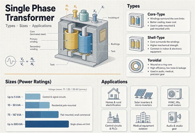
a single phase transformer is one magnetic core with one primary winding and one secondary winding, used wherever the load is single-phase — homes, farms, street lighting, small commercial services, control circuits. Sizes run 5 kVA to 167 kVA on a pole, up to 250 kVA on a pad, and far smaller inside a control panel. What trips buyers up isn’t the principle. It’s that “single phase transformer” covers three genuinely different products governed by three different rulebooks, and most guides treat them as one.
Here’s the thing nobody on page one says out loud: the little dry-type unit in a machine cabinet and the oil-filled can on a utility pole are both “single phase transformers,” and they’re covered by completely different standards, bought from different catalogs, and tested to different rules. Pick the wrong family and your quote comes back for the wrong product.
TransNine Electric builds and exports both kinds, and what follows is the sorting logic we walk buyers through before anyone talks price.
Key numbers
| Item | Value | Why it matters |
| Standard pole-mount ratings | 5, 10, 15, 25, 37.5, 50, 75, 100, 167 kVA | Buy off the ladder; custom ratings cost more and wait longer |
| Practical single-pole ceiling | 167 kVA | Above that you’re on a platform or a pad |
| Pad-mounted single-phase scope | up to 250 kVA | IEEE C57.12.38-2025 |
| Overhead standard scope | ≤500 kVA, ≤34.5 kV | IEEE C57.12.20-2023 |
| 120/240 V center tap | Two 120 V legs plus 240 V across the winding | The defining feature of North American single-phase service |
| Current at 120/240 V | 25 kVA→104 A, 50→208 A, 75→313 A, 100→417 A, 167→696 A | Rating ÷ 240 V |
| Typical single-phase impedance | 2–4% | Lower than three-phase, so fault currents run higher |
| DOE coverage — input | ≤34.5 kV | 10 CFR 431.192 |
| DOE coverage — output | ≤600 V | A 120/240 V secondary is inside; a 4,160 V one isn’t |
| DOE coverage — frequency | 60 Hz | A 50 Hz unit isn’t a “distribution transformer” federally |
| DOE 2029 minimum, 25 kVA liquid | 99.00% at 50% load | 10 CFR 431.196(b)(3), Table 6 |
| DOE 2029 minimum, 167 kVA liquid | 99.46% at 50% load | Same table |
| DOE compliance trigger | Manufactured or imported on or after April 23, 2029 | 89 FR 29834; your PO date is irrelevant |
| 1 kW of loss | 8,760 kWh per year | If the unit sits energized 24/7 |
Which single-phase transformer are you actually buying?
Three families share the name. Sorting yourself into the right one takes about a minute and saves a week.
Family A — small dry-type, inside equipment. Control panels, machine tools, HVAC, lighting cabinets, 480 V down to 120 V for a receptacle. Air-cooled, indoor, usually under 100 kVA and often under 10. Governed by UL 506 (specialty transformers) or UL 5085 (low-voltage transformers), NEMA ST 1, and IEC 60076-11 on the international side. If you’re replacing a unit inside a cabinet, you’re here.
Family B — utility distribution, outdoors. The oil-filled can on a pole or the green box on a pad. Medium-voltage primary (2.4 kV through 34.5 kV), 120/240 V center-tapped secondary, 5 to 167 kVA on a pole, up to 250 kVA on a pad. Governed by IEEE C57.12.20 and C57.12.38. If you’re feeding houses, irrigation pumps, or a small commercial service, you’re here.
Family C — three singles banked into three-phase. Three Family B units wired as a bank. You do this when a three-phase unit can’t get to the site, when you want a spare you can carry in a pickup, or when the utility’s stock and crew training are built around singles.
| Family A: small dry-type | Family B: utility distribution | Family C: bank of three | |
| Where it lives | Inside panels, machines, control cabinets | On a pole or a pad | On a platform or three poles |
| Typical size | Under 100 kVA, often under 10 | 5–167 kVA pole, up to 250 kVA pad | 3 × a standard rating |
| Cooling | Air | Oil or ester | Oil or ester |
| Governing documents | UL 506, UL 5085, NEMA ST 1 | IEEE C57.12.20, C57.12.38, C57.12.00 | Same as B |
| Secondary | 120 V, 240 V, 480 V | 120/240 V center tap | 120/240 V or 120/208 V |
| DOE efficiency table | Table 3 (LV dry-type, 35% load) | Table 6 (liquid-immersed, 50% load) | Per unit |
Almost every guide on this keyword blends A and B. That’s how you end up asking a distribution catalog for a control transformer, or specifying UL 506 on something that should be bought to C57.12.20.
The single-phase cylindrical-winding transformer page goes deep on Family A — winding construction, insulation classes, temperature rise, and a 10 kVA example worked end to end. This guide stays at the category level.
Types: six ways the same box gets built
Classification gets tangled because people mix three axes — how it’s cooled, what it does to the voltage, and how it’s mounted. Here they are separately.
By cooling and insulation.
- Liquid-immersed. Mineral oil or a natural/synthetic ester. Better heat rejection, more overload tolerance, the default outdoors. Fluid choice matters more than people think: esters carry a fire point above 300 °C, which is the threshold that changes how NEC 450.23 treats an installation near combustible construction.
- Dry-type. Cast resin or vacuum-pressure impregnated. No oil, no containment, no leak risk. The default indoors and anywhere fire or environmental rules make oil a headache. Our dry-type transformer range runs 30 kVA to 5,000 kVA, though single-phase dry-type is usually the small end of that.
By what it does to the voltage.
- Step-down — the common case. 12.47 kV to 120/240 V, 480 V to 120 V.
- Step-up — inverter output to collector voltage, or 120 V to 240 V for imported equipment.
- Isolation — two separate windings, no conductive path. You get galvanic isolation and a new neutral reference.
- Autotransformer / buck-boost — one winding with a tap. Cheaper and smaller for small corrections, and it does not give you isolation. Don’t use one where the downstream equipment needs a separately derived system.
That last distinction has a compliance consequence: under 10 CFR 431.192 the federal definition of a distribution transformer excludes autotransformers. So a buck-boost autotransformer sits outside the DOE efficiency tables entirely, while an isolating transformer of the same size sits inside them.
By mounting. Pole (overhead), pad (ground-level, tamper-resistant), platform (two or three singles on a structure), or panel/indoor. On overhead units you’ll also choose conventional vs CSP — completely self-protected, with the fuse, arrester, and secondary breaker built in. CSP means less pole-top hardware and fewer coordination decisions, which is why most utilities specify it for new installs.
Every one of these is a different catalog entry. The full map is on the products page.
Sizes: the ladder, and why the numbers look weird
Utility single-phase ratings step 5, 10, 15, 25, 37.5, 50, 75, 100, 167 kVA. Then the ladder continues at 250 and 333 for platform and pad installations.
Those odd numbers aren’t arbitrary, and here’s the part nobody explains: every one of them is one third of a three-phase bank size. Read the two columns of the DOE efficiency table side by side and it falls out immediately — 10 pairs with 30, 25 with 75, 37.5 with 112.5, 50 with 150, 75 with 225, 100 with 300, 167 with 500, 333 with 1000, 833 with 2500. Three singles of a given rating make a three-phase bank of the matching size. That’s the whole reason 37.5 and 167 exist.
Two practical consequences:
Buy off the ladder. A 120 kVA single-phase unit is a custom build — you’ll pay for engineering and you’ll wait for it. A 100 kVA or a 167 kVA unit is stock-adjacent.
Know where the pole runs out. 167 kVA is the practical ceiling for a single pole-mounted unit. Above that, weight and size push you to a platform or a pad. If your load estimate is sitting right at 170 kVA, go back and check the demand calculation before you redesign the installation around it.
Banking three singles: the numbers behind it
Three single-phase units wired together make a three-phase bank, and there are three reasons to do it: a three-phase unit can’t physically get to the site, you want one carryable spare instead of a whole spare bank, or the utility’s stock and crew training are built around singles.
The arithmetic is simple going in: bank capacity is three times the individual unit rating. Three 50 kVA singles give you a 150 kVA bank. Three 167 kVA units give you roughly 500 kVA. Which is exactly why the single-phase ladder looks the way it does.
Two things catch people out.
An open-delta bank doesn’t deliver two thirds. Run two units instead of three and you get about 57.7% of a closed-delta bank’s capacity, not 67%. That 1÷√3 relationship is why an open-delta installation is usually a deliberate interim step — get service up with two units, add the third when load grows — rather than a permanent design. Size it accordingly, or you’ll overload the two units while the paperwork says you have capacity to spare.
Polarity and vector group are not optional on a bank. Get one unit’s polarity backwards and the bank doesn’t work, or it works badly and runs hot. Specify polarity or vector group on the RFQ and verify it during commissioning. This is also the reason a banked installation wants identical units: mixing ratings or impedances on the same bank splits the load unevenly and heats the smallest one.
The voltage pair: 120/240 V center tap, primary classes, and taps
The secondary is where North American single-phase service differs from everywhere else, and it’s the single most under-explained thing on page one of Google.
A distribution single-phase transformer has a center-tapped secondary winding. From the two ends you get 240 V. From either end to the center tap you get 120 V. That’s why one can feeds both your dryer and your lamps: heavy 240 V loads across the whole winding, 120 V loads split across the two legs.
Rated current follows from the 240 V winding: divide kVA by 240. A 50 kVA unit delivers 208 A; a 100 kVA unit, 417 A; a 167 kVA unit, 696 A.
On the primary side, voltage classes are standardized — 2,400 V, 4,160 V, 7,200 V, 12,470 V, 13,200 V, and up to 34,500 GrdY/19,920 V. Match the class to what the tap point actually delivers, not to the substation nameplate.
Then there’s the tap changer. Distribution units usually come with four or five positions in 2.5% steps, giving roughly ±5% adjustment on the high-voltage winding. If you measure 7,380 V at the cutout on a 7,200 V nominal system, you’re 2.5% high, and you set the +2.5% tap to bring the secondary back to nameplate. Taps are set de-energized. Getting this wrong means chronic high or low voltage at the customer, and it looks like a transformer problem when it isn’t.
One more spec line people skip: BIL, the basic impulse insulation level. It has to match the system insulation class — a 15 kV class primary is commonly paired with 95 kV BIL, a 34.5 kV class with 150 kV BIL. Confirm the pairing against the current IEEE C57.12.00 tables; don’t inherit it from an old spec.
Sizing: a worked example, then the fault current
Take a small commercial building with a 200 A, 120/240 V single-phase service.
Full service capacity is 200 A × 240 V = 48 kVA. But you don’t size the transformer to the service rating — you size it to demand. Say the diversified demand comes out at 32 kVA. The next standard rating up is 37.5 kVA, and if there’s real growth coming, 50 kVA is the better buy because the step costs less than the change-out would.
Now do the step that gets skipped. Calculate the fault current the transformer can deliver, because that sets the interrupting rating of the secondary protection.
For 50 kVA, 240 V, 2.5% impedance:
- Full-load current = 50,000 VA ÷ 240 V = 208 A
- Symmetrical fault current = 208 ÷ 0.025 = 8,333 A, call it 8.3 kA
Single-phase distribution transformers typically run 2–4% impedance, which is lower than the three-phase equivalents — so fault current per kVA is higher than your intuition from three-phase work suggests. Size the secondary breaker and any downstream equipment to the number you just calculated, not to the FLA.
If you want the full parameter-by-parameter walkthrough — how each rating is measured, what the test report has to show — that’s in the resources library.
DOE: the four-question coverage test and the 2029 numbers
Federal efficiency rules attach to the transformer, not to the installation. Under 10 CFR 431.192, a “distribution transformer” is one that:
- Has an input line voltage of 34.5 kV or less
- Has an output line voltage of 600 V or less
- Is rated for operation at 60 Hz
- Has a capacity of 10 kVA to 5,000 kVA liquid-immersed, or 15 kVA to 5,000 kVA dry-type
A 12.47 kV to 120/240 V, 60 Hz single-phase unit clears all four. Swap in a 4,160 V secondary and you’re out on test 2. Order a 50 Hz unit for a 60 Hz system and you’re out on test 3 — which also means it isn’t legal to import as a covered distribution transformer in the first place, and that’s a bigger problem than efficiency.
Thirteen types are also excluded, including autotransformers, drive (isolation) transformers, rectifier transformers, welding transformers, and anything with a tap range of 20% or more.
Here are the actual numbers, which is where every other guide on this keyword goes quiet. Minimum efficiency for single-phase liquid-immersed units manufactured or imported on or after April 23, 2029, at 50% load (10 CFR 431.196(b)(3), Table 6):
| kVA | Min efficiency | kVA | Min efficiency |
| 10 | 98.77% | 167 | 99.46% |
| 15 | 98.88% | 250 | 99.51% |
| 25 | 99.00% | 333 | 99.54% |
| 37.5 | 99.10% | 500 | 99.59% |
| 50 | 99.15% | 667 | 99.62% |
| 75 | 99.23% | 833 | 99.64% |
| 100 | 99.29% |
And for single-phase low-voltage dry-type (input 600 V or less) at 35% load, same date, Table 3:
| kVA | Min efficiency | kVA | Min efficiency |
| 15 | 98.39% | 167 | 99.09% |
| 25 | 98.60% | 250 | 99.16% |
| 37.5 | 98.74% | 333 | 99.23% |
| 50 | 98.81% | 500 | 99.31% |
| 75 | 98.95% | 750 | 99.38% |
| 100 | 99.02% | 1,000 | 99.42% |
Three things to carry into a purchase:
The trigger is the manufacturing or import date, not your PO date. Per DOE’s April 2024 final rule (89 FR 29834), amended levels apply to units manufactured or imported on or after April 23, 2029. A unit built in late 2028 and delivered in 2029 is judged on the old table.
“Meets DOE” is meaningless without the kVA attached. The curve isn’t monotonic in places, and the required number moves with rating. Ask for certified losses at your exact rating.
60 Hz is a legal test, not a preference. A 50 Hz design doesn’t fail the efficiency table so much as it fails the definition — and that’s an import problem.
Where the losses go
Two loss buckets, and they behave differently.
No-load (core) loss is there the moment the unit is energized. It doesn’t care whether anything is plugged in. On a distribution transformer hanging on a pole, that’s 24 hours a day for thirty years.
Load (winding) loss scales with the square of current. It only shows up when you’re drawing power.
You can get a real number out of the efficiency table. A 50 kVA single-phase liquid unit at the 2029 floor of 99.15% measured at 50% load: output is 25 kW, input is 25 ÷ 0.9915 = 25.21 kW, so total loss at half load is about 214 W. Leave it energized all year and that’s 214 W × 8,760 h = 1,875 kWh, roughly $260 a year at an illustrative 13.9 ¢/kWh. Run the same arithmetic at 25 kVA (99.00% floor) and you get about 126 W, or 1,104 kWh a year.
The part that gets missed: a meaningful share of that is core loss, which you pay for whether the unit is loaded or not. On lightly loaded rural feeders — and single-phase rural service is often exactly that — the core is most of the bill. That’s where an amorphous core earns its premium, and why a unit that runs at 25% load deserves a better core rather than heavier conductor.
Applications, and the one spec each one changes
Generic application lists don’t help. What helps is knowing which spec line moves for each job.
| Application | What actually changes on the spec |
| Residential service (1–8 homes) | 25–75 kVA, 120/240 V center tap, CSP with built-in breaker, off-circuit taps |
| Rural / farm / irrigation | Long secondary runs push you up a size for voltage drop; check the tap setting against measured primary |
| Street and area lighting | 120/240 V for LED retrofits, or 240/480 V where the circuit is long; confirm the luminaire input, not the old fixture |
| Small commercial service | 50–167 kVA, load diversity matters more than connected kVA; check fault current against the panel rating |
| Control circuits and machine tools | Family A, dry-type, UL 506 or UL 5085, and decide whether you actually need isolation |
| Solar and storage interconnection | Step-up duty — a 4,160 V or higher secondary moves you outside DOE’s 600 V output test; confirm the utility’s interconnection voltage before quoting |
| Backup / temporary power | Pad-mounted singles move easily; pick a rating that’s already on the ladder so it’s resalable |
| Three-phase from three singles | Bank sizing, vector group, and one spare you can actually lift |
On solar specifically: the step-up direction changes the compliance picture, and the collector-side requirements are their own animal. The 50 MW solar PV step-up project shows what that looks like at scale.
Standards and the US listing path
Know which rulebook applies before you write the RFQ, because “meets international standards” is not an answer an inspector can use.
- IEEE C57.12.20-2023 — Overhead-Type Distribution Transformers 500 kVA and Smaller; High Voltage, 34 500 V and Below; Low Voltage, 7970/13 800Y V and Below. Single- and three-phase, 60 Hz, liquid-immersed, self-cooled. This is the pole-mount document.
- IEEE C57.12.38-2025 — Pad-Mounted-Type, Self-Cooled, Single-Phase Distribution Transformers 250 kVA and Smaller. The pad-mount single-phase document.
- IEEE C57.12.00 — general requirements for liquid-immersed distribution, power, and regulating transformers, including the insulation level pairings.
- IEEE C57.12.28 and C57.12.31 — enclosure integrity and pole-mounted enclosure requirements, which is what “tamper-resistant” is measured against.
- UL 506 / UL 5085 — the listing path for Family A dry-type units in the US market.
- NEMA ST 1 — dry-type specialty transformers.
- NFPA 70 (NEC) — Article 450 covers transformer installation, and 450.3(B) sets maximum overcurrent protection for transformers rated 600 V or less. Confirm the application with your AHJ.
If you’re importing, the IEC-to-ANSI gap is where schedules die. The writeup on IEC 60076 vs ANSI/IEEE standards for export transformers covers the mismatch in detail, and the pad-mounted sizing and pricing guide goes deeper on clearances and site requirements for ground-level units.
The RFQ block
Copy this into your inquiry. Every line is a blank that costs money to get wrong.
Frequently asked questions
What is a single phase transformer?
A transformer with one primary winding and one secondary winding on a single magnetic core, used to change voltage on a single-phase circuit. It’s the standard way to feed homes, farms, street lighting, and small commercial services, and it’s also what sits inside control panels stepping 480 V down to 120 V. Those two jobs are different products with different standards.
What sizes do single phase transformers come in?
Utility distribution units step 5, 10, 15, 25, 37.5, 50, 75, 100, and 167 kVA, with 250 and 333 kVA available for platform and pad mounting. 167 kVA is the practical ceiling for a single pole-mounted unit. Small dry-type units for panels and machines run far smaller, often under 10 kVA.
Why are the ratings 37.5, 167, and 333 kVA instead of round numbers?
Because each one is a third of a three-phase bank size. Three 37.5 kVA singles make a 112.5 kVA bank; three 167 kVA units make roughly 500 kVA; three 333 kVA units make roughly 1,000 kVA. You can see it directly in the DOE efficiency table, where the single-phase and three-phase columns are related by a factor of three.
What does a 120/240 V center-tapped secondary mean?
The secondary winding has a connection at its midpoint. Across the two ends you get 240 V; from either end to the center tap you get 120 V. That’s how one transformer feeds both 240 V appliances and 120 V general-purpose circuits, and it’s the defining feature of North American single-phase service.
How do I size a single phase transformer?
Start with demand, not connected load — apply diversity, then pick the next standard rating above it. A 200 A, 120/240 V service has 48 kVA of capacity, but if diversified demand comes out at 32 kVA the right unit is 37.5 kVA, or 50 kVA if growth is coming. Then check voltage drop on long secondaries, and calculate fault current to size protection.
Do DOE efficiency rules apply to single phase transformers?
Usually yes, and there are published minimums by kVA. Federal coverage requires 60 Hz, an input of 34.5 kV or less, an output of 600 V or less, and 10 to 5,000 kVA liquid-immersed or 15 to 5,000 kVA dry-type. The 2029 levels apply to units manufactured or imported on or after April 23, 2029. Autotransformers are excluded from the definition.
What’s the difference between oil-filled and dry-type single phase transformers?
Oil-filled units cool better, tolerate overload, and are the outdoor utility default. Dry-type units have no oil, no containment, and no leak risk, which is why they go indoors and into fire-sensitive or environmentally sensitive locations. Fluid choice on oil units also affects fire-point rules under NEC 450.23.
Can three single phase transformers make three-phase power?
Yes. Banking three identical singles is standard practice where a three-phase unit can’t reach the site, where you want a carryable spare, or where the utility’s stock is built around singles. Size each unit at one third of the required three-phase bank rating and match vector groups.
What standards apply to single phase distribution transformers in the US?
IEEE C57.12.20-2023 for overhead units 500 kVA and smaller, IEEE C57.12.38-2025 for pad-mounted single-phase units up to 250 kVA, IEEE C57.12.00 for general requirements, and C57.12.28 or C57.12.31 for enclosure integrity. Small dry-type units take the UL 506 or UL 5085 path instead. Installation is governed by NEC Article 450.
How long does a single phase transformer last?
Distribution units commonly see 25 to 30 years of service, and the failure modes are usually external — lightning, overload, moisture ingress, or a bad tap setting — rather than the windings wearing out. The cheapest life extension is sizing it correctly in the first place and setting the tap against the measured primary voltage.