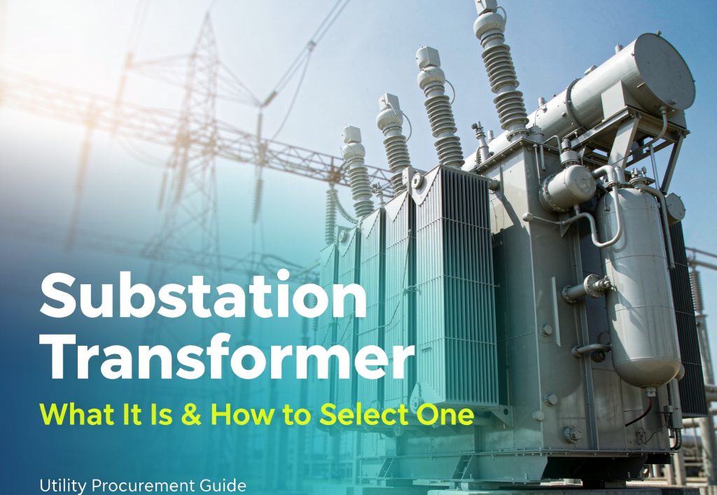
a substation transformer is a power transformer defined by where it sits, not by what it’s rated. It’s the unit that steps voltage between grid levels at a substation. Selecting one comes down to nine decisions — capacity and N-1, voltage ratio and BIL, impedance band, cooling class, tap-changer range, vector group, loss capitalization, the physical transport envelope, and noise/fire provisions. Miss any one and you get a unit that passes every factory test and still doesn’t fit the site.
One thing worth knowing before you read further: the term “substation transformer” gets used for three genuinely different machines, and they’re governed by three different standards. Untangling that is step zero, and almost nobody writing about this topic does it.
Key numbers
| Item | Value | Why it matters |
| DOE “distribution transformer” secondary voltage limit | 600 V or less (10 CFR 431.192) | Substation main transformers sit outside DOE efficiency rules |
| IEEE C57.12.10 scope | ≥833 kVA single-phase, ≥750 kVA three-phase | The standard that governs substation-class power transformers |
| IEEE C57.12.36 scope | Distribution substation transformers, ≤10 MVA, ≤69 kV | A separate standard most buyers have never heard of |
| Power-class impedance, typical | 5%–12% | Sets both fault current and voltage drop |
| Fault current swing, 8% → 12% (20 MVA, 13.8 kV) | 10,460 A → 6,970 A | Same unit, one spec line, 50% difference |
| 1 kW of no-load loss, continuous | 8,760 kWh/year ≈ $1,218/yr at 13.9¢/kWh | The number that decides which quote is actually cheaper |
| 2026 lead time, 5–50 MVA | 75–110 weeks (one source), 60–120 weeks (another), >160 weeks (a third) | Published figures disagree by 20–70 weeks |
| Shipping weight, 100–250 MVA class | 100–300 tonnes | Often decided by the route, not the electrical design |
1. Three different machines get called a “substation transformer”
This is the single most useful thing on this page, so it goes first.
When someone says “substation transformer,” they mean one of three things — and the selection logic is different for each:
| What they mean | Governing standard | Typical band | What actually drives the selection |
| Main substation transformer — the big unit at a transmission or distribution substation | IEEE C57.12.10 (≥833 kVA 1φ / ≥750 kVA 3φ), with C57.12.00 general requirements and C57.12.90 test code | 5–500+ MVA, 69–765 kV | MVA, N-1, impedance band, cooling class, OLTC range, transport envelope |
| Distribution substation transformer | IEEE C57.12.36 (distribution application, up to 10 MVA, 69 kV) | Up to 10 MVA | kVA, voltage regulation on long feeders, fusing and protection |
| Unit substation / compact prefabricated substation | IEC 62271-202 for the assembly; the transformer inside is specified to its own standard | 0.3–5 MVA typical | Footprint, enclosure rating, how tightly the transformer–switchgear–panel package is integrated |
Here’s why the distinction matters in practice. If you ask three suppliers to quote a “substation transformer” without saying which one you mean, you’ll get three quotes that cannot be compared. One will price a 40 MVA ONAN/ONAF unit with an OLTC. One will price a 2.5 MVA distribution substation transformer. One will price a compact substation with a 1,600 kVA cast-resin unit inside. Same words, three orders of magnitude apart in price.
Say which one you mean in the first line of your RFQ.
The rest of this guide is about the first category — the main substation transformer — because that’s where the expensive mistakes happen. Where the compact-substation option is genuinely the better buy, we cover it in section 14.
2. Where the unit sits: transmission vs. distribution substation
A transformer doesn’t care where it’s installed, but every design parameter follows from grid position.
| Transmission substation | Distribution substation | |
| Voltage levels | 69 kV and above; steps between transmission levels | Steps down to distribution primary (e.g. 34.5 → 13.8 kV, 13.8 → 4.16 kV) |
| Typical size | 50–500+ MVA | 5–50 MVA |
| Redundancy | N-1 usually mandatory | N-1 sometimes, sometimes mobile spare |
| Impedance driver | Limit fault duty on a stiff bus | Maintain voltage at the end of long feeders |
| Tap changer | OLTC with a wide range | OLTC or off-circuit, narrower range |
| Cooling | ONAN/ONAF, sometimes OFAF | Usually ONAN, ONAF for contingency |
Notice the impedance row pulls in opposite directions. That’s not an accident, and it’s the subject of section 6.
3. What a substation transformer is not: the DOE 600-volt line
There’s a lot of anxiety in the US market right now about DOE efficiency deadlines. Most of it doesn’t apply to you if you’re buying a substation main transformer — and here’s the specific reason.
DOE’s definition, verbatim from 10 CFR 431.192, says a distribution transformer is a transformer that—
- Has an input line voltage of 34.5 kV or less;
- Has an output line voltage of 600 V or less;
- Is rated for operation at a frequency of 60 Hz; and
- Has a capacity of 10 kVA to 5,000 kVA for liquid-immersed units and 15 kVA to 5,000 kVA for dry-type units.
Condition (2) is the one that matters. A substation main transformer’s secondary is essentially never 600 V or less — it’s 4.16 kV, 13.8 kV, or 34.5 kV. Which means the unit falls outside the definition, and the efficiency tables in Subpart K don’t reach it.
| Unit in your substation | Secondary voltage | In DOE scope? |
| Main power transformer, 115/34.5 kV | 34.5 kV | No — above 600 V |
| Main power transformer, 34.5/13.8 kV | 13.8 kV | No — above 600 V |
| Distribution substation transformer, 34.5/4.16 kV | 4.16 kV | No — above 600 V |
| Station service / auxiliary transformer, 34.5 kV → 480 V | 480 V | Very likely yes — check kVA and the exclusion list |
That last row is the trap. The station service transformer feeding your 480 V auxiliary bus is probably in scope, sitting fifty feet from a unit that isn’t. Same project, same purchase order, two different compliance regimes.
Two more things worth knowing:
- The definition carries thirteen named exclusions, including transformers with a tap range of 20 percent or more and special-impedance transformers. Substation-class units frequently trip one of these anyway.
- The regulatory text is not static. An editorial note on Part 431 records that at 90 FR 43371 (Sept. 9, 2025), under the Congressional Review Act, DOE removed amendments to several sections that had taken effect Dec. 23, 2024 (89 FR 91163), reverting those sections to the Dec. 22, 2024 version.
The practical instruction: check the current eCFR text, and have your compliance counsel confirm applicability before you write an efficiency clause into a substation transformer spec. Don’t copy a DOE efficiency table off a distribution transformer article and paste it into your RFQ — that’s the single most common way a substation spec goes wrong in 2026. It adds cost and buys nothing.
4. Step 1 — Size it: MVA, load factor, and the N-1 decision
Sizing starts from peak load, but peak load alone doesn’t give you an MVA number. Three inputs do.
Input 1: peak load and its growth curve. Size against the 10-year forecast, not today.
Input 2: the N-1 requirement. This is where the money is.
Worked example — peak load 45 MVA, two-unit substation:
| N-1 philosophy | What the surviving unit must carry | Installed capacity | Notes |
| Full N-1 — no assistance from neighbours | 45 MVA | 2 × 50 MVA = 100 MVA | Safe, expensive, lots of idle iron |
| Partial N-1 — 30% transfer to adjacent substations | 31.5 MVA | 2 × 31.5 MVA = 63 MVA | Common in dense urban grids |
| No N-1 — single unit plus mobile spare available in 48 h | 45 MVA | 1 × 50 MVA = 50 MVA | Rural, low load density |
Going from full N-1 to partial N-1 removes 37 MVA of installed capacity from the same substation. That’s not a rounding error — it’s the difference between a two-unit station and a much smaller one, and it’s a planning decision, not an equipment decision. Get it in writing from whoever owns the planning criteria before you size anything.
Input 3: load factor (average load ÷ peak load). This one doesn’t change the MVA rating — it changes which loss profile you should pay for. See section 10.
5. Step 2 — Voltage, BIL, and the Class I / Class II split
Voltage ratio is obvious: 115/34.5 kV, 230/115/34.5 kV, 34.5/13.8 kV. What’s not obvious is that you must also specify:
- System maximum voltage on each winding (not just nominal)
- BIL for each winding and for the neutral
- Whether there’s a tertiary winding and its rating
- Neutral earthing method
BIL (basic lightning impulse insulation level) is the coordinated insulation level, and it follows from voltage class and exposure. Commonly reproduced values from IEEE C57.12.00 Table 2:
| Nominal system voltage | Distribution BIL (kV crest) | Power-class BIL (kV crest) |
| 13.8 kV | 95 | 110 |
| 34.5 kV | 150 | 200 |
| 69 kV | — | 350 |
| 115 kV | — | 450 |
| 230 kV | — | 825 |
Note the distribution-vs-power gap at the same voltage: at 13.8 kV it’s 95 vs 110, and at 34.5 kV it’s 150 vs 200. Same nominal voltage, different test regime. If your spec names the voltage but not the category, you’ve left insulation design to the manufacturer’s interpretation. Confirm values against the current edition of C57.12.00.
Class I vs Class II is a separate axis, and it comes from C57.12.00, not from C57.12.80. Per the IEEE Transformers Committee’s own terminology discussion, C57.12.00 separates power transformers into:
- Class I — high-voltage windings of 69 kV and below
- Class II — high-voltage windings from 115 kV through 765 kV
Later editions treat the 69–115 kV overlap with a size condition (roughly 15,000 kVA and above three-phase, or 10,000 kVA and above single-phase, moving into Class II). Sources differ on exactly how that band is resolved, so name the class explicitly in your spec and confirm it against the edition you’re invoking.
Why bother? Because Class I and Class II are tested to different regimes — induced voltage tests, chopped-wave impulse, dissolved gas analysis, and zero-sequence impedance measurement all differ. It shows up in your FAT plan and in the certificates you receive.
Keep this straight: power vs. distribution is about grid function and comes from IEEE C57.12.80. Class I vs Class II is about insulation level and comes from C57.12.00. A unit can be power-class and Class I, or power-class and Class II — the two axes are independent. On the IEC side, IEC 60076-3 handles insulation coordination and dielectric tests, so if you’re exporting, state which system governs rather than leaving it to be inferred.
6. Step 3 — Impedance: one number, two masters
This is the parameter that causes the most trouble in service, because it answers to two requirements pulling in opposite directions.
Percent impedance (%Z) is the share of rated voltage you’d apply to the HV winding to circulate rated current through a short-circuited LV winding. It sets:
- how much fault current the unit delivers (lower %Z = more fault current), and
- how much voltage drops under load (higher %Z = worse regulation).
Here’s the arithmetic nobody publishes. Take a 20 MVA, 34.5/13.8 kV unit:
| %Z = 8% | %Z = 12% | |
| Three-phase fault MVA | 250 MVA | 167 MVA |
| HV fault current (34.5 kV) | 4,184 A | 2,789 A |
| LV fault current (13.8 kV) | 10,460 A | 6,973 A |
| Approx. voltage drop at full load, pf 0.90 | 3.5% | 5.2% |
| Approx. voltage drop at full load, pf 0.95 | 2.5% | 3.8% |
(Voltage drop approximated as %X × sin φ, valid because the resistive component is small in power-class units.)
Read that table again. Moving impedance from 12% to 8% increases your LV fault current by 50% — 6,973 A to 10,460 A — and every breaker, fuse and bus duct downstream has to be rated for it. Moving the other way costs you about 1.7 percentage points of regulation at 0.9 power factor, which on a 13.8 kV bus is roughly 240 V, and an OLTC range of ±10 × 1.5% covers it comfortably.
Three rules follow:
- Specify a band, not a point. Fleet operators publish an allowable impedance band per size and voltage class, then design downstream equipment for the worst case the band permits. When a unit fails, any compliant transformer in the band is a valid replacement — including one already sitting in your yard. Specify an exact value and a replacement becomes a custom build on a multi-year lead time.
- Check regulation at your actual load power factor. Deriving %Z from a fault study and never checking voltage drop is how you end up with a unit that’s thermally fine and capped by regulation.
- Arc-flash studies use the installed value, not the band. Design for the worst case; label for the actual case.
7. Step 4 — Cooling: ONAN, ONAF, and the dual rating
Cooling class sets the continuous rating. The four-letter code reads: first letter = cooling medium, second = circulation method for the liquid, third = external medium, fourth = its circulation method.
- ONAN — Oil Natural, Air Natural. The base rating. Simplest, quietest, no auxiliary power.
- ONAF — Oil Natural, Air Forced. Fans added; typically lifts capacity meaningfully at the cost of auxiliary power, fan maintenance, and noise.
- OFAF / OFWF — forced oil circulation, for large units and special sites.
Most substation transformers are dual-rated: ONAN for normal service, ONAF for contingency. That’s not an optional upgrade — it’s how you buy N-1 headroom without buying a bigger core. A unit rated 63/75 MVA (ONAN/ONAF) gives you 63 MVA continuously and 75 MVA when the fans run.
Ask two questions: what’s the ONAN rating, and what’s the ONAF rating? A quote that gives one number is hiding something.
Ambient conditions matter more than buyers expect. If the site runs hot — Middle East, parts of Africa, tropical climates — the standard 40 °C ambient assumption doesn’t hold, and radiator area, fan start logic and winding temperature settings all have to be revisited together. The full code breakdown is in our guide to transformer cooling classes.
8. Step 5 — Tap changer: how much range do you actually need?
Two options:
- Off-circuit (de-energized) tap changer — set at commissioning, changed only during an outage. Cheaper, simpler, fewer failure modes.
- On-load tap changer (OLTC) — regulates under load. Essential where system voltage drifts or the transformer feeds a load that swings hard.
The specification errors here are predictable:
Too narrow a range. If your feeders are growing longer, or the grid voltage at your terminal drifts more than it used to, specify the wider range now. Retrofitting a different tap changer after manufacture is not realistically possible.
Wrong type of range. A unit that has to run in parallel with existing transformers needs a tap range covering the impedance of those units at the upper and lower positions — not just at nominal. Parallel operation is where this bites.
Ignoring the maintenance load. An OLTC is the single most maintenance-intensive component on the unit. Ask for the expected operations per day and the maintenance interval, and price the maintenance, not just the box.
9. Step 6 — Vector group, earthing, and tertiary
Vector group determines phase displacement, harmonic behaviour, earthing and protection coordination.
- Dyn11 — the distribution substation default. Delta primary blocks triplen harmonics; star secondary gives you a neutral.
- YNyn0 — used for autotransformers and where both sides need neutral access.
- Dyn1 — a regional alternative to Dyn11.
If the new unit will run in parallel with existing transformers, the vector group must match — this is non-negotiable and it’s checked before anything else at commissioning.
Earthing on the LV neutral (solid, resistance, reactance) sets your ground-fault current and your protection scheme.
Tertiary winding — specify it if you need station auxiliary power, a harmonic trap, or a stabilizing winding. Adding one later means a new transformer.
10. Step 7 — Losses: turning kilowatts into dollars
This is where “cheaper” and “more expensive” quotes routinely swap places.
The two losses behave differently:
- No-load (core) loss — present every hour the unit is energized. 8,760 hours a year, regardless of load.
- Load (copper) loss — scales with the square of load. At 55% load factor, you incur about 0.55² = 30% of rated load loss.
That asymmetry is the whole game. Here’s the conversion:
| Electricity rate | 1 kW of continuous no-load loss, per year | Over 30 years, undiscounted |
| 6 ¢/kWh | $526 | $15,768 |
| 9 ¢/kWh | $788 | $23,652 |
| 13.9 ¢/kWh (EIA US commercial average) | $1,218 | $36,529 |
| 18 ¢/kWh | $1,577 | $47,304 |
Now the worked example. Two quotes on the same 20 MVA unit — these figures are illustrative; substitute your own:
| Quote A | Quote B | |
| No-load loss | 16 kW | 12 kW |
| Load loss at rated | 92 kW | 98 kW |
At a 0.55 load factor (load-loss factor 0.30):
- A: 140,160 + 243,791 = 383,951 kWh/yr
- B: 105,120 + 259,690 = 364,810 kWh/yr
- B wins by 19,141 kWh/yr → about $2,661/yr → roughly $79,800 over 30 years.
At a 0.85 load factor (load-loss factor 0.72):
- A: 140,160 + 582,277 = 722,437 kWh/yr
- B: 105,120 + 620,253 = 725,373 kWh/yr
- A now wins by about $408/yr → roughly $12,200 over 30 years.
The break-even is a load factor of about 0.82. Below it, pay for the better core. Above it, pay for the better copper.
There is no universal answer, and any supplier who tells you their unit is simply “the low-loss one” without asking your load profile hasn’t done the arithmetic. Ask for loss figures at a stated reference temperature, too — the number moves with the temperature basis, and not everyone quotes at the same one.
11. Step 8 — The physical envelope: weight, dimensions, and the route
Substation-class transformers are frequently constrained by how they get to the pad, not by their electrical design. Indicative figures from cargo risk engineering data:
| Class | Shipping weight | Approximate dimensions (L × W × H) | Typical shipping mode |
| Medium power, standard (25–75 MVA) | 25–70 t | 3–5 × 2–3 × 2.5–3.5 m | Flat-rack / breakbulk / Ro-Ro |
| Medium power, heavy (50–125 MVA) | 70–125 t | 4–6 × 2.5–3.5 × 3–4 m | Breakbulk / Ro-Ro; road leg needs SPMT or multi-axle trailer |
| Large power (100–250 MVA) | 100–300 t | 4–8 × 3–4 × 3–4.5 m | Breakbulk / Ro-Ro |
| Generator step-up (200–1,000+ MVA) | 125–550 t | 6–10 × 3.5–5 × 3.5–5 m | Breakbulk; rail or heavy-lift where roads can’t take it |
(Weights and dimensions are indicative only and vary materially by manufacturer and design.)
Ask these before you fix the rating:
- What’s the shipping weight and the transport dimensions, separately?
- Is it shipped complete, or are radiators / bushings / OLTC crated separately?
- Does it travel filled, drained, or under nitrogen?
- Has a route survey been done — bridge clearances, turning radii, gradient, crane capacity at site?
- Is there an impact recorder fitted, and what’s the recorded-g threshold?
Above roughly 100 MVA, route limitations can force design changes: low-profile tanks, split shipments with field assembly, or a bank of single-phase units instead of one three-phase unit. That decision has to happen during specification, not after the order.
12. Step 9 — Noise, fire, and oil containment
Three provisions that get left out of specs and then become change orders.
Noise. Specified in dB(A) at a stated distance, with fans stated as on or off. Near a residential boundary this is often the governing constraint — not electrical at all. Ask for the sound level at both ONAN and ONAF, because the fans are the loud part.
Fire and oil. Mineral oil is the default; ester fluids (higher fire point, biodegradable) are the alternative where fire risk or environmental sensitivity justifies the cost. Then: bund/oil containment sized for the full oil volume, fire separation distances, and whether the AHJ wants a deluge system.
Seismic and wind if the site calls for it. Both are design inputs, not accessories.
13. Lead times in 2026: three sources, three different numbers
Here’s something the industry doesn’t advertise: published 2026 lead-time figures for the same equipment disagree by 20 to 70 weeks. Rather than pick one, here they are side by side.
| Band | ATEK procurement data (June 2026, published 2026-09-01) | Fluxco (2026) | Wood Mackenzie (Q2 2025 survey, published Oct 2025, widely re-reported as “2026”) |
| Substation transformers, 5–50 MVA | 75–110 weeks | 5–20 MVA: 60–90; 20–100 MVA: 90–120 | >160 weeks (vs ~140 in 2023) |
| GSU, >50 MVA | 100–150+ weeks | 100+ MVA: 120–156 | 143–144 weeks |
| Pad-mount, 0–5 MVA | 40–65 weeks | 500 kVA–2.5 MVA: 16–28; 2.5–10 MVA: 24–36 | — |
A caution worth passing on: much of what circulates as “2026 lead times” is Wood Mackenzie’s Q2 2025 survey, published in October 2025 and re-reported through 2026 as though current. It isn’t wrong — it’s a year old. We could not find a published Q2 2026 equivalent.
What this means for a specification, not just a schedule:
- Release the long-lead item first. If the project has one substation-class unit and six distribution-class units, the schedule is set by the one big unit. Order it first.
- Buy the band. The impedance-band logic from section 6 is worth much more in a tight market: a compliant replacement can come from stock instead of a new build.
- Get delivery dates in writing, with a remedy. A quotation is not a slot. Ask what specifically reserves production capacity.
- Freeze the specification early. Late changes reset the production queue.
14. When a compact substation is the better buy
Sometimes the right answer isn’t a substation transformer at all — it’s a compact prefabricated substation.
| Choose a conventional substation transformer when… | Choose a compact / prefabricated substation when… |
| Rating is above roughly 5–10 MVA | Rating is 0.3–5 MVA |
| You need N-1 redundancy and a spare unit strategy | Single unit plus a mobile spare is acceptable |
| Long asset life and rebuildability matter | Speed of deployment is the binding constraint |
| The site has space, foundations and civil works | The site is tight, urban, or temporary |
| You’re stepping between transmission levels | You’re making the final step to utilization voltage |
A compact substation integrates the transformer, MV switchgear and LV panel into one factory-tested enclosure, and is governed as an assembly (IEC 62271-202 for HV/LV prefabricated substations) rather than purely as a transformer. It’s not a compromise — for the right application it’s faster to energize and cheaper to install. We’ve documented a utility EPC programme built around this approach in our 11 kV / 33 kV compact substation programme case study.
15. Why we’re not printing a price table
Published 2026 price bands for substation-class transformers differ by three to five times for the same nominal rating, and the spread is dominated by things that aren’t the MVA number:
| Cost driver | Effect |
| Loss guarantees (capitalized value) | A tighter no-load guarantee can add six figures of lifetime value — or cost |
| Impedance outside the standard band | Custom design, not a catalog build |
| Cooling class and dual rating | ONAF adds fans, controls, auxiliary power, noise mitigation |
| OLTC vs off-circuit | Substantial, and it recurs in maintenance |
| BIL above the standard level for the class | More insulation, bigger clearances, larger tank |
| Transport class | Split shipment and field assembly change the logistics cost more than the unit price |
Rather than print a number we can’t stand behind, here’s the instruction: specify the unit completely, then get three quotes on the identical spec. Price comparison is only meaningful when the specifications are identical, and on substation-class equipment they almost never are.
16. The spec sheet: 16 fields your RFQ must answer
A substation transformer RFQ that lists only voltage and MVA isn’t a specification. It produces quotes you can’t compare and a unit that fails acceptance for a reason nobody wrote down.
| # | Field | Example entry |
| 1 | Which of the three types (section 1) | Main substation transformer |
| 2 | Rated capacity, and ONAN / ONAF ratings | 63/75 MVA |
| 3 | Voltage ratio and system maximum voltage | 115/34.5 kV |
| 4 | Frequency and phases | 60 Hz, 3-phase |
| 5 | BIL, each winding and neutral | HV 450 kV, LV 200 kV |
| 6 | Class I or Class II | Class II |
| 7 | Impedance — give a band | 10% ±1% at 63 MVA base |
| 8 | Cooling class | ONAN / ONAF |
| 9 | Tap changer type and range | OLTC, ±10 × 1.5% |
| 10 | Vector group | YNd11 |
| 11 | Neutral earthing | LV resistance earthed, 400 A |
| 12 | No-load loss and load loss, with stated reference temperature | Guaranteed, with $/kW penalty |
| 13 | Temperature rise limits | 55/65 °C |
| 14 | Noise level, ONAN and ONAF, at stated distance | ≤75 dB(A) at 1 m, fans on |
| 15 | Shipping weight and transport dimensions | Stated separately, with route survey |
| 16 | Governing standard and edition, plus test code | IEEE C57.12.10-2017, C57.12.90 |
Two clauses that earn their keep:
- Loss guarantees with a dollar penalty — e.g. $/kW of excess no-load and load loss, measured at the FAT. This converts a marketing number into a contractual one.
- Impedance tolerance, stated as a band with a measurement method — not “approximately.”
17. Before you send the RFQ: the nine-decision checklist
- ☐ Which of the three machine types am I actually buying?
- ☐ Is the secondary above or below 600 V — and therefore in or out of DOE scope?
- ☐ What’s my N-1 philosophy, in writing, from the planning authority?
- ☐ Have I specified BIL for each winding and the neutral, plus Class I/II?
- ☐ Is impedance a band, and have I checked both fault duty and regulation at my real power factor?
- ☐ Do I have both ONAN and ONAF ratings?
- ☐ Is the tap range wide enough for ten years of feeder growth and for parallel operation with existing units?
- ☐ Have I converted losses to dollars using my own load factor?
- ☐ Do I know the shipping weight, dimensions, and whether a route survey exists?
If you’re still at the equipment-class level — deciding between oil-immersed and dry-type, or working through ratings and applications for large-capacity units — our 35 kV large-capacity power transformer guide covers that layer, and the Power Transformer: Complete Buying Guide for 2026 goes deeper on the equipment category itself. This page is the grid-position layer — where the unit sits and what that forces on the design.
Frequently asked questions
What is a substation transformer? A power transformer installed at a substation that changes voltage between grid levels — for example 115 kV to 34.5 kV, or 34.5 kV to 13.8 kV. It’s defined by its position in the network, not by a rating or a class. Every substation transformer is a power transformer, but not every power transformer sits in a substation.
What’s the difference between a substation transformer and a power transformer? “Power transformer” is a functional class under IEEE C57.12.80: it transfers energy anywhere between the generator and the distribution primary circuits. “Substation transformer” is a power transformer in a specific location. The distinction is geographic and functional, not electrical.
Is a substation transformer the same as a distribution transformer? No. A distribution transformer makes the final step down to utilization voltage and serves load directly; a substation transformer steps between network levels. Under 10 CFR 431.192, DOE’s regulatory definition of a distribution transformer requires an output of 600 V or less — a threshold substation transformers essentially never meet.
Do DOE efficiency standards apply to substation transformers? Generally no, for the main transformer. DOE’s distribution transformer definition at 10 CFR 431.192 requires an output line voltage of 600 V or less; substation main transformers step to 4.16 kV, 13.8 kV or 34.5 kV and fall outside it. The station service transformer feeding a 480 V auxiliary bus is a different matter and is likely in scope. Confirm against the current eCFR text with your compliance counsel.
What size substation transformer do I need? Peak load sets the floor; the N-1 requirement sets the answer. For a 45 MVA peak on a two-unit station, full N-1 implies 2 × 50 MVA, while partial N-1 with 30% transfer to neighbours implies 2 × 31.5 MVA — a 37 MVA difference in installed capacity for the same peak load.
What impedance should I specify? There’s no single right value. Power-class units typically fall between 5% and 12%. Specify an allowable band sized to your fault duty, and check voltage regulation at your expected load power factor at the same time. On a 20 MVA 34.5/13.8 kV unit, moving from 12% to 8% raises LV fault current from about 6,970 A to about 10,460 A.
Should I specify ONAN or ONAF? Most substation transformers are dual-rated: ONAN for continuous service, ONAF for contingency. Ask for both numbers. A quote giving only one is incomplete.
Do I need an on-load tap changer? If system voltage at your terminal drifts, or the load swings hard, yes. If the grid is stable and the load predictable, an off-circuit tap changer costs less and has fewer failure modes. Either way, size the range for ten years of change — a tap changer cannot be practically retrofitted.
What are Class I and Class II power transformers? A split in IEEE C57.12.00 based on insulation level and test regime, not on function. Class I covers high-voltage windings of 69 kV and below; Class II covers 115 kV through 765 kV, with the 69–115 kV overlap resolved by size in later editions. Name the class explicitly in your specification and confirm it against the edition you invoke.
How much does a substation transformer cost? Published 2026 bands for the same rating differ by three to five times, because the drivers — loss guarantees, impedance band, cooling class, OLTC, BIL and transport class — dominate the MVA number. Specify completely, then get three quotes on the identical specification. Any single number quoted without the full spec is not comparable.
How long does a substation transformer take to deliver? Published 2026 figures disagree: ATEK’s June 2026 procurement data puts 5–50 MVA at 75–110 weeks; Fluxco puts 5–20 MVA at 60–90 weeks and 20–100 MVA at 90–120 weeks; Wood Mackenzie reported more than 160 weeks, though that figure comes from a Q2 2025 survey published in October 2025. Get the date in writing from the supplier who will actually ship it.
When should I buy a compact substation instead? Below roughly 5 MVA, where deployment speed matters more than rebuildability, where the site is tight or temporary, or where you want a factory-tested transformer–switchgear–panel package rather than three separate procurements.