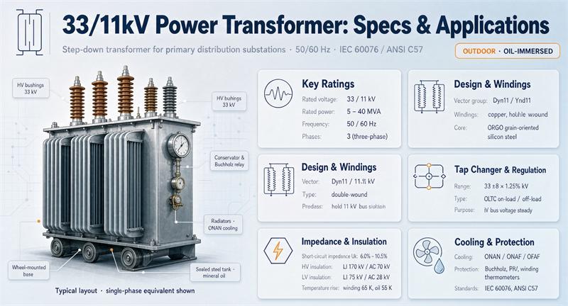
A 33/11 kV power transformer steps 33 kV down to 11 kV, and it is the single most common machine sitting in a primary (or “zone”) distribution substation across IEC markets: Africa, South Asia, Southeast Asia, the Middle East, much of Australia and the UK. Typical ratings run from about 1.6 MVA up to 63 MVA, almost always three-phase, oil-immersed, 50 Hz, with an on-load tap changer above roughly 5 MVA.
Here is the part most buying guides skip. A 10 MVA unit will burn somewhere between 200,000 and 233,000 kWh a year doing nothing but existing, which at $0.10/kWh is about $20,000 to $23,000 a year, or roughly $248,000 to $289,000 in present-value terms over 30 years at a 7% discount rate. The machine itself, depending on whose price list you believe, costs $80,000 to $180,000. So the electricity it wastes over its life is worth one and a half to three times the machine. That gap is where the real specification work happens, and it is also where almost every published page on this keyword stops.
This guide walks through what the ratings actually mean, the twelve spec lines that move the price, the two current tables nobody publishes, why impedance climbs with size, what four different datasheets say about the same 10 MVA machine, where these units get installed, what one weighs when it shows up on a truck, and what changes if you are buying for 60 Hz. There is a copy-paste RFQ block near the end and a full source list with retrieval dates.
What “33/11kV” actually means
The ratio is a nominal system voltage on each side, not the voltage the equipment is built and tested to. On an IEC machine each winding carries its own highest voltage for equipment, written Um, and the insulation schedule follows from Um, not from the nominal number.
For a 33/11 kV transformer the two values are Um 36 kV on the high side and Um 12 kV on the low side. That is not a rounding convention someone invented for marketing. A utility specification says it out loud: West Bengal State Electricity Distribution Company’s technical specification for 6.3 MVA and 10 MVA 33/11 kV transformers calls for a 36 kV class HV bushing and a 12 kV class LV bushing, with the LV neutral brought out through its own porcelain bushing. Two bushing classes, one machine.
Once you have Um, IEC 60076-3 gives you the withstand levels. For Um 36 kV the power-frequency withstand is 70 kV rms and the lightning impulse level is either 145 kV or 170 kV depending on which list the standard’s table is read from. For Um 12 kV it is 28 kV rms with a lightning impulse of either 60 kV or 75 kV. Both Scotech’s shipped 10 MVA unit for South Africa and Vziman’s 33/11 kV product page publish the higher pair: LI 170 kV / AC 70 kV on the HV, LI 75 kV / AC 28 kV on the LV.
That “either” matters more than it looks. A supplier quoting to the lower list is offering a legitimately different machine, and the difference will show up in bushing creepage, clearances and what the test certificate says. Ask which list the offer is built to, and make the test report show 170 kV and 75 kV if that is what your specification calls for.
One more thing about the ratio itself. “33/11 kV” describes the windings at the principal tap. The tap changer moves it: ±8 × 1.25% on the HV is typical for a 10 MVA unit with an OLTC, and Vziman and Scotech both publish exactly that range. Yawei’s 20 MVA unit for a Sudan substation uses 33 kV ±9 × 1.67%, which is 17 positions. A 17-position changer and a 17-step range are not the same thing, so confirm both the number of steps and the step size before you compare quotes.
The 12 specs that decide what you pay
Every one of these lines changes the price, the delivery date, or what happens in year fifteen. Most of them get one line in a catalogue and three paragraphs in a dispute.
| Spec line | What it controls | Typical value on 33/11 kV | What goes wrong if you leave it vague |
|---|---|---|---|
| Rated power | Size, weight, losses, price | 1.6 to 63 MVA | You get a machine sized to today’s load with no headroom |
| Voltage ratio and Um | Bushing class, insulation, clearances | 33/11 kV, Um 36/12 kV | A 35 kV-class design gets shipped against a 33 kV spec |
| Vector group | Earthing, harmonic path, protection | Dyn11, YNd11 | LV neutral you need is not brought out |
| Impedance | 11 kV fault level, voltage drop, short-circuit forces | 6.5% at 5 MVA to 12% at 63 MVA | Your 11 kV board is underrated, or your voltage drop is too high |
| No-load loss | 24/7 energy cost | 7.8 to 12.4 kW at 10 MVA | You pay for it every hour for 30 years |
| Load loss at 75 °C | Energy cost under load | 47.7 to 60 kW at 10 MVA | Same, scaled by load factor squared |
| Cooling class | Continuous and emergency capacity | ONAN, ONAF, OFAF | “ONAF” with no fan rating specified |
| Temperature rise | Insulation aging rate | 60 K top oil, 65 K winding (IEC 60076-2) | Hotter machine, shorter life |
| Tap changer | Voltage regulation under load | DETC below ~5 MVA, OLTC above | Outages every time the grid moves |
| Tap range and steps | How far you can regulate | ±8 × 1.25%, ±9 × 1.67% | Range too narrow for your feeder |
| Insulation fluid | Fire risk, containment, aging | Mineral oil, natural ester | Ester specified with no viscosity check at your ambient |
| Noise | Siting and permits | 55 to 85 dB(A) | Neighbour complaints and a retrofit you pay for |
Two of those lines deserve more than a row.
The first is impedance, and it gets its own section below because it is the one that quietly drives the cost of everything downstream on the 11 kV side.
The second is the fluid. Mineral oil is the default and the cheapest. Natural ester costs more and buys you a higher fire point and better moisture tolerance, which is why it shows up in data centres, tunnels and anywhere the AHJ treats oil as a hazard. Ester is more viscous, so cooling behaves differently at low ambient temperatures, and it is not a drop-in on every design. If you want ester, say so in the RFQ rather than discovering it as an option later.
Amps on both sides, and why the 11 kV side carries three times as much
This is arithmetic any engineer can do, and almost no manufacturer page publishes it. Full-load current is MVA divided by (√3 × kV), which gives a constant per MVA:
- 33 kV side: 17.495 A per MVA
- 11 kV side: 52.486 A per MVA
The ratio is exactly 3, because the voltage ratio is 3. Here is what that looks like across the usual ladder.
| Rating | 33 kV side FLA | 11 kV side FLA |
|---|---|---|
| 1.6 MVA | 28 A | 84 A |
| 2.5 MVA | 44 A | 131 A |
| 5 MVA | 87 A | 262 A |
| 6.3 MVA | 110 A | 331 A |
| 10 MVA | 175 A | 525 A |
| 12.5 MVA | 219 A | 656 A |
| 16 MVA | 280 A | 840 A |
| 20 MVA | 350 A | 1,050 A |
| 25 MVA | 437 A | 1,312 A |
| 31.5 MVA | 551 A | 1,653 A |
| 40 MVA | 700 A | 2,100 A |
| 63 MVA | 1,102 A | 3,307 A |
Two practical consequences. The 33 kV side is a modest-current circuit: a 10 MVA unit draws 175 A, which is why 33 kV cable and switchgear on the incoming side are comparatively cheap. The 11 kV side is where the copper goes, and above about 1,250 A you are into multiple cables per phase or busbar trunking on the LV terminals, which changes the termination arrangement and the drawing.
It also explains a spec detail that catches people out. On a 10 MVA machine the LV bushings and any in-tank CTs have to be sized for 525 A, not 175 A. If a quote gives HV and LV bushings at the same current rating, that is worth a question.
What your 11 kV board will actually see
The transformer’s own contribution to a fault on the 11 kV bus is its full-load current divided by its per-unit impedance. Written out:
Isc = FLA ÷ Z
This is an upper bound, because it ignores the impedance of the 33 kV source behind the transformer, which only reduces the number. It is still the right first check, because it tells you whether the switchgear you are about to buy is even in the right decade.
| Rating | Impedance | 11 kV FLA | Transformer contribution |
|---|---|---|---|
| 5 MVA | 6.5% | 262 A | 4.0 kA |
| 6.3 MVA | 7.15% | 331 A | 4.6 kA |
| 8 MVA | 7.5% | 420 A | 5.6 kA |
| 10 MVA | 8.35% | 525 A | 6.3 kA |
| 12.5 MVA | 8% | 656 A | 8.2 kA |
| 16 MVA | 8% | 840 A | 10.5 kA |
| 20 MVA | 8% | 1,050 A | 13.1 kA |
| 25 MVA | 9.5% | 1,312 A | 13.8 kA |
| 31.5 MVA | 10% | 1,653 A | 16.5 kA |
| 40 MVA | 10.75% | 2,100 A | 19.5 kA |
| 63 MVA | 12% | 3,307 A | 27.6 kA |
Standard 12 kV switchgear built to IEC 62271-100 comes rated at 25 kA, 31.5 kA or 40 kA. So a single 33/11 kV transformer almost never stresses the board: a 10 MVA machine contributes about 6.3 kA against a 25 kA rating, and there is a lot of room.
That room disappears the moment you parallel. Two identical 10 MVA units on one 11 kV bus halve the effective impedance to 4.175% on a 20 MVA base, and the contribution becomes:
- 1 × 10 MVA: 6.3 kA
- 2 × 10 MVA: 25.1 kA
- 3 × 10 MVA: 56.6 kA
Two units land at 25.1 kA, which is a 25 kA board with nothing left. Three units need more than even a 40 kA board, so the answer at that point is a split bus, a bus-section reactor, or a deliberate decision to run them on separate sections. This is the single most useful number in the whole exercise and no page ranking for this keyword publishes it.
For contrast, look at the 33 kV side. The same 10 MVA unit at 8.35% contributes 2.1 kA on the 33 kV bus, and even a 63 MVA unit at 12% only contributes 9.2 kA. The transformer is not what sets your 33 kV switchgear rating; the upstream network’s declared fault level is. Spending money on a special transformer impedance to protect 33 kV gear is spending it in the wrong place.
Why impedance goes up as the transformer gets bigger
Read any manufacturer’s ladder and you will see impedance climbing steadily with rating. Evernew’s 33/11 kV guide, which is the only ranking page with a real numeric ladder, goes like this:
| Rating | Cooling | Impedance band | Typical vector group |
|---|---|---|---|
| 5 MVA | ONAN | 6.0% to 7.5% | Dyn11 / YNd11 |
| 10 MVA | ONAN / ONAF | 7.5% to 8.5% | YNd11 |
| 20 MVA | ONAN / ONAF | 8.5% to 9.5% | YNd11 |
| 25 MVA | ONAN / ONAF | 9.0% to 10.0% | YNd11 |
| 40 MVA | ONAF | 10.0% to 11.5% | YNd11 |
| 63 MVA | ONAF / OFAF | 11.5% to 12.5% | YNd11 |
The published ladder is not the only evidence. WBSEDCL’s tender specification fixes 7.15% at 6.3 MVA and 8.35% at 10 MVA. Yuguang’s series table shows 6.5% at 630 kVA, 7% around 3.15 MVA and 7.5% around 6.3 MVA. Scotech’s shipped 10 MVA unit is 8%. Yawei’s 20 MVA unit is 8%, which sits at the low end of Evernew’s band and is a good reminder that these are bands, not laws.
Why does it climb? Two reasons, and they point in different directions.
The first is fault level. Look at what happens if you held impedance flat at 6.5% all the way up the ladder. A 63 MVA unit at 6.5% would contribute 50.9 kA on the 11 kV bus, and there is no standard 12 kV board that handles it. Pushing impedance to 12% brings that back to 27.6 kA, which a 31.5 kA board can carry. Higher impedance is what keeps the downstream switchgear purchasable.
The second is mechanical. The force on the windings during a short circuit scales with the square of the current, so a bigger machine at lower impedance has to be built to survive forces that grow fast. IEC 60076-5 is the standard covering that ability to withstand, and it is referenced on Vziman’s datasheet right next to the impedance figure. Making the windings survive 50 kA of through-fault is expensive steel and expensive clamping.
The cost of high impedance is voltage drop and regulation, which is exactly why the bigger units carry an OLTC with a wide range. You are trading regulation for fault containment, and buying back the regulation with a tap changer.
Vector group is an earthing decision, not a checkbox
Catalogues list vector groups like a menu. Dowei lists Dyn11, Dyn5, YNd11 and Yyn0 on one page. Evernew lists Dyn11 or YNd11 at 5 MVA and YNd11 from 10 MVA up. Scotech’s shipped 10 MVA unit is YNd1. Vziman’s product page is also YNd1.
Two vendors publishing YNd1 is worth slowing down for. YNd11 and YNd1 describe different phase displacement between the windings, not two spellings of the same thing. If your specification says YNd11 and the quote comes back YNd1, that is a real difference and it needs to be resolved in writing before the drawings are approved. We are not going to call either one wrong, because we cannot verify the convention each vendor is using, but we can tell you it is not a typo you should wave through.
The decision underneath the code is simpler than the code suggests:
- Dyn11 puts the delta on the 33 kV side and the star on the 11 kV side. You get an 11 kV neutral you can earth directly, and the delta blocks zero-sequence transfer from the 33 kV side. This is the usual choice at the smaller end of the ladder and wherever the 11 kV network needs a neutral at the transformer.
- YNd11 puts a star (often with the neutral brought out) on the 33 kV side and the delta on the 11 kV side. Utilities favour it from about 10 MVA up, because the HV neutral can be earthed in a controlled way and the 11 kV side runs as a delta bus with earthing done at the board, often through a zig-zag or earthing transformer.
- Yyn0 has a star on both sides. It is increasingly avoided on new designs above small ratings because of third-harmonic and neutral-loading behaviour, and you should expect a supplier to push back on it.
The delta somewhere in the machine is not optional in practice. It gives the third-harmonic currents somewhere to circulate and it gives zero-sequence current a path, and both of those change how your protection behaves. If you are specifying a star-star arrangement, you are very likely specifying a delta tertiary at the same time, and that tertiary has its own rating and its own cost.
Whatever you pick, write down what the neutral has to do. WBSEDCL’s specification goes as far as requiring in-tank current transformers under the LV neutral bushing (and under all three phase bushings on the 10 MVA unit) so that restricted earth-fault and differential protection can be wired. That is a design decision, and it is much cheaper on the drawing than in the field.
Losses: four datasheets, one machine, and a crossover at 50% load
Here is what four independent published sources say about a 10 MVA 33/11 kV transformer. All figures are no-load loss and load loss at 75 °C.
| Source | No-load loss | Load loss | Impedance | Peak-efficiency load |
|---|---|---|---|---|
| WBSEDCL tender spec (utility) | 10.0 kW | 57.0 kW | 8.35% | 41.9% |
| Scotech, unit shipped to South Africa 2025 | 7.8 kW | 60.0 kW | 8% | 36.1% |
| Yuguang Electric, 33 kV series table | 10.88 kW | 47.7 kW | not stated | 47.8% |
| GNEE Electric, quoted with ±15% | 12.40 kW | 56.80 kW | 9% | 46.7% |
The spread on no-load loss is 7.8 to 12.4 kW, which is 59% from lowest to highest, on the same rating and the same voltage ratio. On load loss it is 47.7 to 60 kW. These are not different machines with different prices in any visible way; they are different design choices about core steel versus copper.
Peak efficiency is nowhere near full load. It sits at the load factor where no-load loss equals load loss times the square of the load, which is the square root of the ratio:
peak load factor = √(no-load loss ÷ load loss)
For these four machines that is 36% to 48%. If anyone tells you a transformer runs best at 70% to 85% loading, they are describing a thermal or a planning rule, not the efficiency peak. The efficiency peak is around 40% to 50%, and it is calculable from two numbers on the datasheet.
Now the part that actually decides which datasheet you should want. Total loss at a given load factor is NL + LL × (LF)². Run it across the range:
| Load factor | WBSEDCL | Scotech | Yuguang | GNEE | Best |
|---|---|---|---|---|---|
| 15% | 11.28 kW | 9.15 kW | 11.95 kW | 13.68 kW | Scotech |
| 25% | 13.56 kW | 11.55 kW | 13.86 kW | 15.95 kW | Scotech |
| 35% | 16.98 kW | 15.15 kW | 16.72 kW | 19.36 kW | Scotech |
| 50% | 24.25 kW | 22.80 kW | 22.80 kW | 26.60 kW | tie |
| 65% | 34.08 kW | 33.15 kW | 31.03 kW | 36.40 kW | Yuguang |
| 80% | 46.48 kW | 46.20 kW | 41.41 kW | 48.75 kW | Yuguang |
| 100% | 67.00 kW | 67.80 kW | 58.58 kW | 69.20 kW | Yuguang |
Scotech and Yuguang cross over at almost exactly 50% load. (Our arithmetic: set 7.8 + 60x² = 10.88 + 47.7x², solve, x = 0.500.) Below 50% you want the low-core-loss design. Above 50% you want the low-copper-loss design. GNEE’s numbers never win at any load factor, because its no-load loss is the highest and its load loss is not low enough to compensate.
That is the whole answer to “which quote has the best losses”: it depends on your load profile, and you cannot tell without asking.
Now turn it into money. At 50% load, 8,760 hours a year, $0.10/kWh, and a 30-year present-value factor of 12.409 at 7%:
| Source | Loss at 50% | kWh per year | Dollars per year | 30-year present value |
|---|---|---|---|---|
| WBSEDCL | 24.25 kW | 212,430 | $21,243 | $263,604 |
| Scotech | 22.80 kW | 199,728 | $19,973 | $247,842 |
| Yuguang | 22.80 kW | 199,772 | $19,977 | $247,897 |
| GNEE | 26.60 kW | 233,016 | $23,302 | $289,150 |
For a 20 MVA unit using Yuguang’s figures (18 kW no-load, 83.7 kW load), the same method gives 38.9 kW at 50% load, 340,983 kWh a year, $34,098 a year, and $423,126 over 30 years.
There is a second way to do this, and it is the one utilities actually use. WBSEDCL’s tender document does not discount a stream of kilowatt-hours. It publishes capitalised rates and adds them straight to the bid price:
- Iron (no-load) loss: Rs 668,304 per kW
- Copper (load) loss: Rs 200,492 per kW
On its own 10 MVA figures that is Rs 6,683,040 for the core loss plus Rs 11,428,044 for the load loss, about Rs 18.1 million added to the bid. The same specification forbids bidders from declaring any tolerance on those loss figures, which is the right instinct, and it is worth writing into your own RFQ.
One more thing falls out of those two numbers. The ratio of the copper rate to the iron rate is 200,492 ÷ 668,304 = 0.300. Since load loss runs at load factor squared, the load factor implied by that ratio is √0.300, which is 54.8%. Our arithmetic, not a published figure, but it tells you what load factor that utility is implicitly designing around, and you can compare it with your own.
Finally, watch the tolerance. GNEE quotes its 10 MVA losses as “±15%”. A loss figure with a 15% tolerance is not a commitment. IEC 60076-1 allows tolerances on losses, and the standard’s default is not zero, so if you want the number to hold, cap it in the purchase order and attach the same penalty structure the utility uses.
Cooling: what the second rating really buys
The four-letter code reads in pairs: first the internal cooling medium and how it moves, then the external one.
- ONAN: oil natural, air natural. Natural convection inside and out. No fans, no pumps, no controls. This is the base rating.
- ONAF: oil natural, air forced. Fans on the radiators. Same machine, higher continuous rating.
- OFAF: oil forced, air forced. Pumps and fans.
- ODAF: oil directed forced, air forced. Pumps push oil through guided paths in the windings.
A machine sold as 10/12.5 MVA ONAN/ONAF is a 10 MVA machine that can carry 12.5 MVA with the fans running. That is 25% more capacity for the cost of a fan bank and its controls, and it is the cheapest capacity in the whole project, provided you ask three questions: what is the rating at each stage, what happens if a fan fails, and are the fans fed from a secure supply.
Temperature rise is the limit underneath all of it. IEC 60076-2 for oil-immersed units gives a top-oil rise of 60 K and an average winding rise by resistance of 65 K, over a 40 °C ambient with a 24-hour average of 30 °C. Scotech’s datasheet for its shipped 10 MVA unit states exactly those two numbers, 60 K and 65 K. Hot-spot behaviour is handled separately in IEC 60076-7 and it is the number that actually drives aging, so if you are specifying for a hot site, ask for the hot-spot calculation rather than the two average figures.
Altitude matters too. The standard ratings assume 1,000 m or below. Above that the air is thinner, cooling gets worse, and you either derate or specify a design built for it.
If you want the full walkthrough of the codes and what each stage costs you in capacity, our guide to transformer cooling classes covers ONAN through OFAF in detail. The construction choices behind those codes, tank and radiator and conservator arrangements, sit on the oil-immersed transformer side of the catalogue.
Where 33/11 kV transformers get used
Primary distribution substations. This is the home application. A utility takes 33 kV in, steps to 11 kV, and feeds a dozen or more 11 kV feeders out. Two transformers in parallel with a bus section is the standard arrangement, which is exactly where the 25.1 kA figure from earlier becomes relevant.
Industrial parks and large plants. A plant with its own 33 kV intake steps down to 11 kV and distributes at 11 kV around the site, with smaller 11/0.4 kV units at each block. This is why Vziman and Scotech both market 33/11 kV units specifically for industrial parks.
Mining. Long 11 kV runs to pit equipment, plus a lot of starting and stopping, which is where the mechanical strength covered by IEC 60076-5 earns its keep.
Renewable collection. Solar and wind plants often collect at 33 kV and then step down to 11 kV for the local network, or step up from 33 kV to the transmission voltage instead. Note the difference: a 33/11 kV unit here is a step-down for the local network, whereas the plant connection itself is usually a step-up unit. Don’t let the two get confused in one RFQ.
Data centre campuses. A campus intake at 33 kV, an 11 kV distribution ring, and 11/0.4 kV units at each building. Fire behaviour is usually the deciding factor between oil and cast resin at the last step, not at the 33/11 kV stage.
Rail and metro. Traction and auxiliary supplies, where the 11 kV side often feeds rectifier transformers rather than a distribution board.
Airports, ports, hospitals. Anywhere with an 11 kV network already in the ground and a 33 kV supply arriving.
Where 33/11 kV is the wrong answer: if you have no 11 kV network and your load is all low voltage, a direct 33/0.4 kV unit (practical up to roughly 2 to 2.5 MVA) saves you an entire voltage level. The 33/11 kV choice only pays for itself when there is 11 kV to distribute.
We have run a 11 kV and 33 kV compact substation programme for an overseas utility EPC that shows how this looks when the transformer, the 11 kV board and the enclosure are specified as one package. More installation examples are in the project portfolio.
Size, weight, oil, and getting it to site
A 33/11 kV power transformer is not a distribution transformer you can offload with a forklift. Yawei’s published figures for a 20 MVA 33/11 kV unit built for a Sudan substation give the three numbers you need:
- Weight without oil: 25,000 kg (55,115 lb)
- Transport weight: 31,000 kg (68,343 lb)
- Gross weight: 39,000 kg (85,980 lb)
The gap between the last two is the oil. 39,000 minus 25,000 is 14,000 kg of oil, which at a typical mineral oil density of about 0.87 kg/L is roughly 16,100 litres, or about 4,250 US gallons.
Two things follow.
First, you need a crane and a route survey. 31 tonnes on a truck is an abnormal load in most jurisdictions, and the route from the port to the plinth needs checking for bridge ratings, turning radii and overhead clearance before the unit ships, not after.
Second, if the site is in the United States, that oil volume matters for a regulatory reason. EPA’s Spill Prevention, Control and Countermeasure rule at 40 CFR 112 applies to non-transportation-related facilities with more than 1,320 US gallons of oil in above-ground containers that could reasonably be expected to discharge into navigable waters, and it counts oil-filled electrical equipment toward the total. One 20 MVA unit at roughly 4,250 gallons is about 3.2 times the threshold on its own. You do not need several transformers to trigger an SPCC plan here; you need one.
For any rating, ask for oil mass and transport weight on the outline drawing at bid stage. Do not scale the 20 MVA figures linearly down to 5 MVA; the relationship is not linear, and the drawing is free.
Price and lead time
Published price indications for 10 MVA 33/11 kV oil-immersed units, retrieved 2026-10-13:
| Source | 10 MVA 33/11 kV | Basis as stated |
|---|---|---|
| Jiangsu Subian, brand comparison | $90,000 to $160,000 | 33 kV class power transformer |
| Jiangsu Subian, brand table | $80,000 to $150,000 | Mid-tier Chinese exporter |
| Jiangsu Subian, brand table | $90,000 to $180,000 | Major Chinese OEMs (TBEA, Baoding Tianwei) |
| Jiangsu Subian, brand table | $150,000 to $280,000 | Korean makers (Hyosung, Hyundai, ILJIN) |
| Jiangsu Subian, brand table | $170,000 to $350,000 | ABB, Siemens, Schneider, Hitachi Energy |
| Alibaba buying guide | $130,000 to $250,000+ | 10 to 20 MVA, includes ester-filled |
For smaller units, the Alibaba guide puts a 5 MVA 33/11 kV oil unit at $30,000 to $95,000, and Ruist’s solar price guide puts 5 MVA 33/11 kV or 35/10.5 kV at $45,000 to $120,000. Same rating, two guides, ranges that barely overlap.
Treat all of it as an order of magnitude, not a budget. The clearest proof of why: Yawei’s product listing for a 20 MVA 33/11 kV unit shows a price band of $18,900 to $38,900, which cannot be right for a machine with 25 tonnes of steel and 14 tonnes of oil in it. Every other source puts 10 to 20 MVA units above $130,000. Listings like that are template artefacts, and they are the reason a price table without a date, an Incoterm and a winding-material statement is worthless.
On lead time, the numbers that matter are weeks, not days. Subian’s published guidance says large-unit lead times currently run 30 to 50 weeks, and that a 20 to 32 week queue is typical for the well-known brands. If your project schedule has four months in it, you are buying whatever is available, not what you would have specified. Our power transformer buying guide goes through the procurement sequence in more detail.
What changes at 60 Hz and in North America
33/11 kV is an IEC pairing, built around 50 Hz. The North American counterpart is 34.5 kV to 13.8 kV (or 34.5/12.47 kV), at 60 Hz. Same job, different standards, and the insulation schedule is not the same.
Per Voltimum’s Table 1.1-5, which reproduces the ANSI/IEEE C57.12.00 schedule, the bolded standard BIL at 34.5 kV is 200 kV crest for both the distribution and power classes, with 150 kV and 125 kV in common use. For the 13.8 kV side, which sits in the 15 kV class, the power-transformer BIL is 110 kV with 95 kV in common use.
Put that next to the IEC machine and the contrast is sharp:
| IEC 33/11 kV | ANSI 34.5/13.8 kV | |
|---|---|---|
| HV impulse level | LI 145 or 170 kV | BIL 200 kV (150 and 125 in use) |
| HV power-frequency | 70 kV rms | 70 kV applied test |
| LV impulse level | LI 60 or 75 kV | BIL 110 kV (95 in use) |
| LV power-frequency | 28 kV rms | 34 kV applied test |
The low-side impulse level on the ANSI machine is roughly 50% higher, even though the two systems are within a couple of kilovolts of each other. That is a standards-schedule difference, not a physics one, and it is why you cannot simply relabel an IEC design for a US project.
Two more things from C57.12.00 worth knowing. Its Table 3 footnote states that the listed nominal system voltages cover other nearby voltages, giving 15 kV as covering 14,440 / 13,800 / 13,200 / 13,090 / 12,600 / 12,470 / 12,000 and 11,950 V, so a 13.8 kV winding is specified from the 15 kV class row. And the standard caps average winding temperature rise at 65 °C by resistance with a hottest-spot limit of 80 °C, against IEC 60076-2’s 60 K top-oil and 65 K winding. The winding average limit is the same number in both systems; the top-oil and hot-spot framing is where they diverge.
If you are buying an IEC-design machine and running it on 60 Hz, the direction matters. A 50 Hz design on 60 Hz generally runs cooler and can often carry its rating, subject to confirmation. A 60 Hz design run on 50 Hz is the dangerous direction: flux rises in proportion to the drop in frequency, so you have to reduce the applied voltage by the same ratio or the core saturates. Get it in writing from the manufacturer, with the frequency and voltage both stated.
The full standard-by-standard comparison, including what changes for testing and documentation on export projects, is in our IEC 60076 versus ANSI/IEEE overview.
A copy-paste RFQ
Send this as the technical schedule. Every line that has a number in it should come back with a number.
1.  Rated power:            _______ MVA, continuous, at _______ cooling stage
2.  Voltage ratio:          _______ / _______ kV, at principal tap
3.  Highest voltage Um:     HV _______ kV,  LV _______ kV
4.  Frequency:              _______ Hz
5.  Phases:                 3
6.  Vector group:           _______   (state whether LV neutral is brought out)
7.  Impedance at principal tap:  _______ %, tolerance _______ %
8.  No-load loss:           _______ kW, guaranteed, max tolerance _______ %
9.  Load loss at 75 deg C:  _______ kW, guaranteed, max tolerance _______ %
10. Insulation levels:      HV LI _______ / AC _______ ;  LV LI _______ / AC _______
11. Cooling:                _______ ; second rating _______ MVA at _______
12. Temperature rise:       top oil _______ K, winding _______ K, hot spot _______ K
13. Tap changer:            DETC / OLTC, range _______ x _______ %, positions _______
14. Fluid:                  mineral oil / natural ester / other _______
15. Ambient:                max _______ C, min _______ C, altitude _______ m
16. Noise at rated load:    _______ dB(A)
17. Accessories required:   Buchholz, PRD, OTI, WTI, oil level, conservator /
                            sealed, CTs (location and ratio), marshalling box
18. Tests:                  IEC 60076 routine set, plus _______
19. Loss capitalisation:    no-load $_______ /kW, load $_______ /kW (state your rates)
20. Delivery:               _______ weeks from order, Incoterm _______
21. Documents:              outline drawing with transport weight and oil mass,
                            routine test reports, type test reports for _______
Two lines do most of the work. Line 19 makes suppliers compete on losses instead of on sticker price, and it moves the bid more than any other line in the document. Line 21 makes sure you find out the transport weight before the truck is booked.
If you want a longer version with the commercial terms and inspection clauses, the resources library has the full buying-guide series, and the product catalogue shows the rating families.
Bottom line
Three things decide a 33/11 kV purchase, and none of them is the sticker price.
Impedance sets what your 11 kV switchgear has to interrupt, and it climbs with rating for exactly that reason. One 10 MVA unit contributes 6.3 kA, two in parallel contribute 25.1 kA against a standard 25 kA board, and that is the number that quietly determines whether your substation design survives contact with a real switchgear catalogue.
Losses decide the lifetime bill. Four published datasheets for the same 10 MVA machine disagree by 59% on no-load loss, the peak-efficiency point sits at 36% to 48% load rather than anywhere near full load, and the better design flips at almost exactly 50% load factor depending on your duty cycle. Capitalise them at your own rates, or borrow a utility’s, and add the result to the bid.
Vector group decides your earthing. It is not a menu item, and two vendors quoting YNd1 where most of the industry writes YNd11 is a real difference worth resolving on paper.
Do those three and the rest of the specification is ordinary engineering.
FAQ
What does 33/11kV mean on a transformer nameplate?
It is the nominal system voltage on each winding: 33 kV on the high-voltage side, 11 kV on the low-voltage side, at the principal tap. It is not the voltage the insulation is designed to, which is given by the highest voltage for equipment, Um 36 kV and Um 12 kV respectively. The tap changer moves the ratio around the principal tap, commonly by ±8 × 1.25% or ±9 × 1.67%.
Is a 33/11kV transformer a distribution transformer or a power transformer?
Both labels get used and the distinction is not settled by a capacity threshold in IEC. In practice, ratings from about 1.6 MVA to 63 MVA get sold as 33/11 kV, and above roughly 5 MVA they are built as power transformers with an OLTC, a conservator and full protection accessories. Under IEEE C57.12.00 a 34.5 kV-class machine falls in the Class I power transformer category, which carries its own insulation schedule.
What are the insulation levels I should specify?
For an IEC machine: Um 36 kV on the HV with a 70 kV rms power-frequency withstand and a lightning impulse of 145 kV or 170 kV, and Um 12 kV on the LV with 28 kV rms and a lightning impulse of 60 kV or 75 kV. Most published datasheets quote the higher pair, 170 kV and 75 kV. State which you want and require the test certificate to show it.
How many amps does a 10 MVA 33/11kV transformer draw?
175 A on the 33 kV side and 525 A on the 11 kV side, at full load. The per-MVA constants are 17.495 A per MVA at 33 kV and 52.486 A per MVA at 11 kV, so you can scale for any rating.
What fault current will it put on my 11 kV bus?
Full-load current divided by per-unit impedance, as an upper bound before you add source impedance. A 10 MVA unit at 8.35% gives about 6.3 kA. A 20 MVA unit at 8% gives 13.1 kA. Two 10 MVA units in parallel give 25.1 kA, which is already at the standard 25 kA rating for IEC 62271-100 12 kV switchgear.
Why does impedance increase with transformer size?
Two reasons. Higher impedance limits the fault current the downstream switchgear has to interrupt: a 63 MVA unit at 12% contributes 27.6 kA, while the same unit at 6.5% would contribute over 50 kA, which no standard 12 kV board handles. It also reduces the mechanical forces the windings must survive under short circuit, which is covered by IEC 60076-5. The trade is worse voltage regulation, which is why larger units carry an on-load tap changer.
Should I choose Dyn11 or YNd11?
Dyn11 puts the delta on the 33 kV side and gives you an earthable 11 kV neutral at the transformer, which suits smaller units and networks that need the neutral there. YNd11 puts the star on the 33 kV side and the delta on the 11 kV side, which utilities favour from about 10 MVA up, with 11 kV earthing handled at the board. Several published 33/11 kV datasheets also show YNd1, which is a different phase displacement from YNd11; if your specification says one and the quote says the other, resolve it before approving drawings.
What are typical losses for a 10 MVA 33/11kV transformer?
Four published sources give no-load losses between 7.8 kW and 12.4 kW, and load losses at 75 °C between 47.7 kW and 60 kW. The peak-efficiency load factor, the square root of no-load loss over load loss, lands between 36% and 48%. At 50% load the total is 22.8 to 26.6 kW, worth about $20,000 to $23,000 a year at $0.10/kWh.
How much does a 33/11kV power transformer cost?
Published indications for 10 MVA range from about $80,000 for mid-tier Chinese exporters to $350,000 for the largest global brands, with most sources clustering between $90,000 and $180,000. A 5 MVA unit is quoted between $30,000 and $120,000 depending on the source. These figures are order-of-magnitude only: they carry no consistent date, Incoterm or winding-material basis, and one listing for a 20 MVA unit shows $18,900, which cannot be correct.
How long is the lead time?
Published guidance for large units currently runs 30 to 50 weeks, with a 20 to 32 week queue typical for well-known brands. Plan the procurement around the switchgear and civils, not the other way round.
Can a 33/11kV transformer run on 60 Hz?
A 50 Hz design generally runs cooler on 60 Hz and can often carry its rating, but it needs manufacturer confirmation. The reverse is the dangerous case: a 60 Hz design on a 50 Hz supply sees higher core flux and must be run at a proportionally lower voltage. The 60 Hz equivalent pairing is 34.5 kV to 13.8 kV, with BIL levels of 200 kV and 110 kV rather than 170 kV and 75 kV.
How much does a 20 MVA unit weigh and how much oil does it hold?
A published listing for a 20 MVA 33/11 kV unit gives 25,000 kg without oil, 31,000 kg transport weight and 39,000 kg gross. The difference implies about 14,000 kg of oil, roughly 16,100 litres or 4,250 US gallons. That is about 3.2 times the 1,320 gallon threshold in the US SPCC rule at 40 CFR 112, so a single unit of that size can require a spill prevention plan on its own.