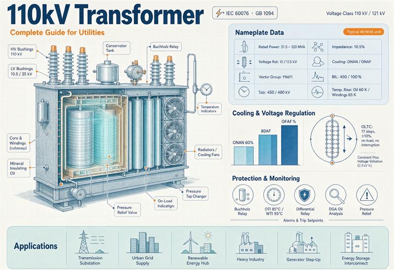
A 110 kV transformer is the machine that closes the gap between the transmission network and everything below it. It takes 110 kV and steps it down to 35 kV, 11 kV, 10.5 kV or 6.3 kV, and it sits in primary substations, industrial intake points, wind and solar collector substations and traction feeds. Ratings most often land on 31.5, 40, 50 and 63 MVA, three-phase, oil-immersed, 50 Hz, with an on-load tap changer once you get past roughly 16 MVA.
Here is the number that should frame the whole purchase. The US Department of Agriculture publishes a loss evaluation guide for rural utilities, RUS Bulletin 1724E-301, and it walks through a real 30/40/50 MVA tender. Manufacturer A bid $424,500 with 59 kW of no-load loss and 224 kW of load loss. Manufacturer B bid $436,000 with 53 kW and 218 kW. Capitalized at the rates in that guide, A’s losses are worth $438,158 and B’s are worth $416,012. So B wins the evaluated total by about $10,600 even though B’s sticker price is $11,500 higher. On both bids, the capitalized losses are worth 95% to 103% of the purchase price.
Almost every page written on this keyword tells you to “compare losses, not just price” and then stops. This guide does the arithmetic instead. It covers what 110 kV actually means as a piece of equipment, the two insulation systems in one machine, the current and fault-current tables nobody publishes, why impedance matters in a specific way at this class, how utilities really award these tenders, what the EU efficiency floor does to a design that would be perfectly legal in Texas, what a 50 MVA unit weighs and how much oil it holds, and what one costs in 2026. There is a copy-paste RFQ block near the end.
What “110 kV” actually means as equipment
110 kV is a nominal system voltage. It is not the voltage the transformer is designed and tested to. Every winding carries its own highest voltage for equipment, written Um, and the insulation schedule comes from Um.
For a 110 kV system the IEC value is Um 123 kV. Once you have that, IEC 60076-3 gives you the withstand levels: a short-duration power-frequency withstand of 185 kV rms, and a lightning impulse level of 450 kV or 550 kV depending on which list of the standard’s table you read. Both the Energypac catalogue, which reproduces IEC 76-3 Section 5 Table II, and a published insulation-coordination reference give the same pair: 450 to 550 kV impulse against 185 to 230 kV rms.
Two lists, two machines. A supplier quoting to the lower list is offering a legitimately different design with different bushing creepage, different clearances and a different test certificate. Since the standard’s own note says the lowest value in the table is the minimum, the lower list is what you get unless your specification says otherwise. If your arrester study, your pollution class or your altitude calls for the higher level, write 550 kV into the enquiry and make the test report show it.
Now the part that surprises people. In North America, the ANSI/IEEE C57.12.00 schedule for power transformers lists 115 kV nominal with a standard BIL of 550 kV, with 450 and 350 kV noted as levels in common use. So the top of the IEC range and the ANSI standard are the same number, 550 kV. But the IEC floor is 450 kV, one full step below the ANSI standard. A machine built and tested to IEC list 1 is not automatically the machine a US utility expects on a 115 kV bus.
| System | Nominal | Um / class | Power-frequency withstand | Lightning impulse |
|---|---|---|---|---|
| IEC 110 kV | 110 kV | Um 123 kV | 185 kV rms | 450 kV (list 1) / 550 kV (list 2) |
| IEC 132 kV | 132 kV | Um 145 kV | 230 kV rms | 550 kV / 650 kV |
| GB 35 kV secondary | 35 kV | Um 40.5 kV | 85 kV external / 80 kV internal | 200 kV |
| ANSI 115 kV power | 115 kV | 115 kV class | per C57.12.00 Table | 550 kV standard, 450 and 350 in use |
| ANSI 69 kV power | 69 kV | 69 kV class | per C57.12.00 Table | 350 kV standard, 250 in use |
The GB row is there because a lot of 110 kV machines are specified as 110/35 kV. Note what that means: the high side is an IEC Um row and the low side is a GB Um row. They are not the same standard family, and the secondary insulation level has to be agreed explicitly rather than assumed from the ratio.
If you want the full side-by-side of how the two standards families treat the same machine, our write-up on IEC 60076 versus ANSI/IEEE for export transformers goes through it in more depth.
Two windings, two insulation systems
A 110/11 kV transformer is not one insulation design with two voltages stamped on it. Each winding has its own Um, its own test voltages and usually its own bushing class.
The high side is Um 123 kV. The low side, at 10.5 or 11 kV, is Um 12 kV, which per the same IEC table is 28 kV rms with a lightning impulse of 60 or 75 kV. That is a factor of more than six between the two windings on the same core, and it is why the LV bushings look like something off a distribution transformer while the HV bushings are taller than a person.
The neutral is separate again. A clause-by-clause guide to IEC 60076-3:2013 puts the neutral applied-voltage test at a minimum of 38 kV for a directly earthed neutral on windings above Um 72.5 kV. If your neutral is earthed through an impedance, the neutral Um and test levels are yours to specify, and the standard requires Um to be no less than 17.5 kV in that case. Get it in writing. A neutral bushing that is quietly specified down is a cheap way to win a bid and an expensive way to lose a machine.
Ratings and the current table you will actually use
Amps per MVA at a given line-to-line voltage is a constant, and once you have it you can size bushings, cables, CTs and busbar in your head.
| Voltage | Amps per MVA |
|---|---|
| 110 kV | 5.249 |
| 115 kV | 5.020 |
| 121 kV | 4.771 |
| 35 kV | 16.496 |
| 21 kV | 27.493 |
| 13.8 kV | 41.837 |
| 11 kV | 52.486 |
| 10.5 kV | 54.986 |
| 6.6 kV | 87.477 |
| 6.3 kV | 91.643 |
So a 50 MVA 110/11 kV unit runs 262 A on the high side and 2,624 A on the low side. A 63 MVA 110/10.5 kV unit runs 331 A and 3,464 A. Those two numbers drive the HV cable or overhead termination and the LV busbar or cable count, and they are the first thing a panel builder will ask for.
| Rating | 110 kV side | 11 kV side | 10.5 kV side | 6.3 kV side |
|---|---|---|---|---|
| 10 MVA | 52 A | 525 A | 550 A | 916 A |
| 16 MVA | 84 A | 840 A | 880 A | 1,466 A |
| 20 MVA | 105 A | 1,050 A | 1,100 A | 1,833 A |
| 25 MVA | 131 A | 1,312 A | 1,375 A | 2,291 A |
| 31.5 MVA | 165 A | 1,653 A | 1,732 A | 2,887 A |
| 40 MVA | 210 A | 2,099 A | 2,199 A | 3,666 A |
| 50 MVA | 262 A | 2,624 A | 2,749 A | 4,583 A |
| 63 MVA | 331 A | 3,307 A | 3,464 A | 5,773 A |
| 80 MVA | 420 A | 4,199 A | 4,399 A | 7,331 A |
Ratings ladder the way you would expect from IEC preferred values: 6.3, 8, 10, 12.5, 16, 20, 25, 31.5, 40, 50, 63, 80, 120 MVA. Our oil-immersed power transformer range covers this class up through the larger ratings.
Impedance and the fault-current wall
Impedance on a 110 kV two-winding unit sits around 10.5% across the whole ladder. Tailong publishes 10.5% for its S13 series from 20 to 63 MVA, Yuguang publishes 10.5% from 6.3 to 63 MVA, Kerun publishes 10.5% from 6.3 to 63 MVA. Three independent data sheets, same number, no ladder. That is different from the distribution world, where impedance climbs with size.
Because impedance is flat, the fault current the transformer can feed into a bus scales almost perfectly with rating. At 11 kV and 10.5% the constant is 0.4999 kA per MVA.
| Rating | Fault current into an 11 kV bus (upper bound) | Nearest IEC 62271-100 preferred rating |
|---|---|---|
| 20 MVA | 10.0 kA | well inside 25 kA |
| 31.5 MVA | 15.7 kA | inside 25 kA |
| 40 MVA | 20.0 kA | inside 25 kA |
| 50 MVA | 25.0 kA | dead on 25 kA, zero margin |
| 63 MVA | 31.5 kA | dead on 31.5 kA, zero margin |
| 80 MVA | 40.0 kA | dead on 40 kA, zero margin |
Those are upper bounds, because they assume an infinite source behind the transformer. The real number is lower, and how much lower depends on the grid. But the pattern matters: at 50, 63 and 80 MVA the transformer alone can source exactly the standard breaker rating. Add any contribution from the network and from motors on the bus and you are over. These three ratings are where 11 kV switchgear stops being a formality and becomes a design exercise.
Shift the secondary and the same arithmetic moves with it. At 10.5 kV multiply by 1.047, so 50 MVA gives 26.2 kA instead of 25.0. At 6.3 kV multiply by 1.746, and 50 MVA gives 43.6 kA, which pushes you past 40 kA entirely. At 35 kV divide by about 3.2, and 50 MVA gives only 7.9 kA.
Now the other side of the machine. A 50 MVA unit contributes just 2.50 kA into a 110 kV fault. A 63 MVA unit contributes 3.15 kA. Compare that with 31.5 kA on the 11 kV side and the conclusion writes itself: the low-voltage bus is where impedance bites, and the high-voltage switchgear rating is set by the declared fault level of the grid you are connecting to, not by your transformer. If you are paying extra for a special impedance to protect the 110 kV board, you are buying the wrong thing.
Paralleling is where this gets expensive. Two identical 50 MVA units on a common 11 kV bus give an effective impedance of 5.25% at 100 MVA, which is 99.97 kA. Three units give 224.9 kA. There is no 11 kV switchgear at those ratings for a normal substation. Splitting the bus, or adding reactors, is not optional at that size.
One design shows up repeatedly precisely because it solves this: the three-winding 110/35/10 kV unit. Yuguang publishes HV-to-LV impedance of 18 to 19%, HV-to-MV of 10.5% and MV-to-LV of 6.5% for that construction. The high HV-to-LV figure is not a penalty. It means a 31.5 MVA three-winding unit feeds only about 9.4 kA into its 10 kV bus where a 31.5 MVA two-winding unit would feed 16.5 kA. The third winding is a built-in fault limiter, and it is why utilities with constrained 10 kV networks keep specifying them even at a higher purchase price.
The vector group is a grounding decision
YNd11 for two-winding units, YNyn0d11 for three-winding. That is what the manufacturers publish, and it is consistent across Tailong, Yuguang and Runsheng.
The star on the high side gives you a neutral to earth, which is what makes the 110 kV system effectively earthed and lets you run graded insulation and sensitive earth-fault protection. The delta on the low side gives zero-sequence current somewhere to circulate, so a ground fault on the LV winding does not show up as a disturbance on the HV side.
On three-winding units the delta tertiary is load-bearing for the same reason. If the tertiary is a stabilizing winding with no external terminals, say so in the enquiry and ask for its thermal rating, because a stabilizing winding that is too small will overheat during an earth fault on the LV system.
Watch the clock number. If your specification says YNd11 and the quotation says YNd1, those are different phase relationships. Neither is wrong in the abstract, but they are not interchangeable, and connecting one where the other was designed in will stop you from paralleling with the existing fleet. Confirm it in writing.
Losses: how utilities actually decide who wins
This is the section that matters most on this class of equipment, and it is the one every published page on 110 kV transformers waves at and walks past.
There is no federal efficiency floor for a 110 kV transformer in the United States. The DOE tables in 10 CFR 431.196 cover liquid-immersed distribution transformers with a primary at or below 34.5 kV and a secondary at or below 600 V. A 110 kV machine fails both tests on the first line. So there is nothing to comply with, and utilities fill that gap themselves with a loss evaluation clause.
The method is simple. You publish a dollar value per kilowatt of no-load loss and a dollar value per kilowatt of load loss, you multiply each bidder’s guaranteed losses by those numbers, and you add the result to the bid price. Whoever has the lowest evaluated total wins. RUS Bulletin 1724E-301 gives this as standard contract language, and includes the worked example quoted at the top: $2,450 per kW of no-load loss, $1,304 per kW of load loss and $756 per kW of auxiliary loss on a 30/40/50 MVA transformer.
Two other published rate sets, for scale: Guam Power Authority’s specification E-034 uses $6,640 per kW no-load and $3,610 per kW load. A trade summary of utility practice puts OECD utility factors at $2,500 to $5,500 per kW no-load and $700 to $1,500 per kW load over 30 years at a 5 to 6% discount rate.
The ratio between the two factors tells you something. In the RUS example the load factor is 0.532 of the no-load factor, and in the Guam specification it is 0.544. If you read that ratio as load factor squared, both work out to about 73 to 74% loading. That is our arithmetic, not a published figure, but it is a useful sanity check: these utilities are not discounting load losses very hard, which means a design that trades load loss for no-load loss will not automatically win.
What the published loss numbers actually look like
| Source and design | Rating | No-load loss | Load loss at 75 °C |
|---|---|---|---|
| Kerun, Type 22 (class 1) | 50 MVA | 21.0 kW | 175 kW |
| Kerun, Type 20 (class 2) | 50 MVA | 24.8 kW | 175 kW |
| Kerun, Type 18 (class 3) | 50 MVA | 30.6 kW | 187 kW |
| Tailong S13 | 50 MVA | 34.0 kW | 189 kW |
| Yuguang SFZ11 | 50 MVA | 38.2 kW | 194 kW |
| Tailong S13 | 63 MVA | 40.6 kW | 227 kW |
| Yuguang SFZ11 | 63 MVA | 45.4 kW | 232 kW |
Same rating, five numbers, and the no-load loss spreads by a factor of 1.82. At the RUS rate of $2,450 per kW, the 17.2 kW gap between the best and worst 50 MVA figure is $42,140 of evaluated cost on a machine that costs somewhere in the low hundreds of thousands. Run the same gap as pure energy at $0.10/kWh over 8,760 hours a year and 30 years at a 7% discount rate, using a present-value factor of 12.409, and it is about $187,000.
Part of that spread is legitimate. Kerun labels three efficiency classes explicitly, and the class 1 design is simply a lower-loss machine that costs more to build. The rest of the spread is what happens when a specification says “50 MVA, 110/11 kV, ONAN/ONAF” and says nothing else. If you do not name the efficiency class, you are asking five manufacturers to bid five different machines and then comparing them on price.
Peak efficiency is not at full load. The load factor at which losses are lowest is the square root of no-load divided by load loss, and across this sample that lands at 34.6% to 44.4%. A 110 kV transformer is at its best around 40% loading, which is also roughly where a substation transformer with N-1 reserve actually spends its life. It is not a reason to oversize; it is a reason to ask for guaranteed losses at the loading you expect, not just at rating.
The European floor that most of these designs miss
The European Union does regulate this class. Regulation (EU) 548/2014 defines a large power transformer as one above 3,150 kVA with an insulation class above 36 kV, or any unit at or above 40 MVA regardless of voltage. A 110 kV transformer is a large power transformer under either reading.
For liquid-immersed large power transformers the regulation sets a minimum Peak Efficiency Index rather than maximum losses. The Tier 2 values, in force since 1 July 2021, are:
| Rating (MVA) | Minimum PEI, Tier 1 (2015) | Minimum PEI, Tier 2 (2021) |
|---|---|---|
| 20 | 99.639% | 99.684% |
| 31.5 | 99.671% | 99.712% |
| 40 | 99.684% | 99.724% |
| 50 | 99.696% | 99.734% |
| 63 | 99.709% | 99.745% |
| 80 | 99.723% | 99.758% |
| 100 and above | 99.737% | 99.770% |
PEI works out, ignoring the power drawn by the cooling system, as 1 minus 2 times the square root of (no-load loss times load loss), divided by rated power. Run that on the published data sheets and the result is uncomfortable:
| Design | Rating | No-load | Load | PEI (upper bound) | Tier 2 floor | Result |
|---|---|---|---|---|---|---|
| Kerun Type 22 | 31.5 MVA | 14.9 kW | 111 kW | 99.742% | 99.712% | clears |
| Kerun Type 20 | 31.5 MVA | 17.6 kW | 111 kW | 99.719% | 99.712% | clears |
| Kerun Type 18 | 31.5 MVA | 21.6 kW | 117 kW | 99.681% | 99.712% | misses by 0.031 |
| Kerun Type 22 | 50 MVA | 21.0 kW | 175 kW | 99.758% | 99.734% | clears |
| Kerun Type 20 | 50 MVA | 24.8 kW | 175 kW | 99.736% | 99.734% | clears |
| Kerun Type 18 | 50 MVA | 30.6 kW | 187 kW | 99.697% | 99.734% | misses by 0.037 |
| Tailong S13 | 31.5 MVA | 24.0 kW | 133 kW | 99.641% | 99.712% | misses by 0.071 |
| Tailong S13 | 50 MVA | 34.0 kW | 189 kW | 99.679% | 99.734% | misses by 0.055 |
| Tailong S13 | 63 MVA | 40.6 kW | 227 kW | 99.695% | 99.745% | misses by 0.050 |
| Yuguang SFZ11 | 31.5 MVA | 27.0 kW | 123 kW | 99.634% | 99.712% | misses by 0.078 |
| Yuguang SFZ11 | 50 MVA | 38.2 kW | 194 kW | 99.656% | 99.734% | misses by 0.078 |
| Yuguang SFZ11 | 63 MVA | 45.4 kW | 232 kW | 99.674% | 99.745% | misses by 0.071 |
Thirteen of the sixteen published numbers miss. That is our arithmetic using a simplified PEI relationship that ignores cooling-system power, so treat each figure as an upper bound and the misses as conservative. It is also not a claim that those manufacturers cannot build a compliant machine. Kerun’s own class 1 and class 2 numbers clear the floor, which shows the capability exists. The point is narrower and more useful: you have to name the efficiency class in the enquiry, because the default product on this voltage level is not automatically placeable on the EU market.
If losses are the deciding line in your tender, our low-loss power transformer range is built around that premise, and the complete power transformer buying guide walks through capitalisation in more detail.
Cooling, temperature rise and noise
ONAN is the base rating and ONAF is the first step up, with OFAF and ODAF appearing on the larger ratings and on generator step-up duty. Tailong’s S13 data sheet carries ONAN/ONAF across 20 to 63 MVA, and Kerun’s SZ series is the same. Cooling stage matters for your evaluation because losses are guaranteed at a specific stage and reference temperature, and RUS-type evaluation clauses apply a separate rate to auxiliary losses, which are the fan and pump power.
Temperature rise under IEC 60076-2 is 60 K on top-oil and 65 K on the winding average. The North American schedule is framed differently, with a 65 °C average winding rise by resistance and an 80 °C hottest-spot limit, so the two families agree on the winding average and diverge on how they treat the top oil and the hot spot. Load loss should be corrected to 75 °C on IEC machines and 85 °C on ANSI machines before you compare, and the correction is not symmetric.
Noise is usually quoted as a sound power level, not the sound pressure you will measure at the fence. Tailong lists 62 dB(A) at 20 MVA rising to 67 dB(A) at 63 MVA as sound power. If your substation has a residential boundary, specify the test to IEC 60076-10 and ask for both the sound power level and the sound pressure level at a stated distance and direction.
What it weighs, how big it is, and how it gets there
| Rating | Total weight | Transport weight | Dimensions (L × W × H) |
|---|---|---|---|
| 31.5 MVA | 52 t (114,600 lb) | 42 t (92,600 lb) | 6,800 × 4,800 × 5,400 mm (22.3 × 15.7 × 17.7 ft) |
| 50 MVA | 74 t (163,100 lb) | 58 t (127,900 lb) | 7,200 × 5,300 × 5,700 mm (23.6 × 17.4 × 18.7 ft) |
| 50 MVA, second source | 82 t (180,800 lb) | 57 t (125,700 lb) | 7,610 × 5,720 × 5,610 mm (25.0 × 18.8 × 18.4 ft) |
| 63 MVA | 81 t (178,600 lb) | 63 t (138,900 lb) | 7,600 × 5,600 × 5,900 mm (24.9 × 18.4 × 19.4 ft) |
The tank alone on a 50 MVA unit is 5.6 to 5.7 m tall, before it meets a trailer. Add deck height and you are into route survey territory, and route survey means escort vehicles, and sometimes temporary removal of overhead spans. One manufacturer describes inland movements of a 40 MVA unit on police-escorted hydraulic modular trailers with crates 8 to 11 m long. Plan the civils around the delivery route, not the other way round. Radiators, bushings and the conservator usually travel separately and are fitted on site, which is why transport weight sits well below total weight.
Oil is the other half of the site work.
| Rating | Oil mass | Volume | US gallons | Multiple of the 1,320 gallon SPCC line |
|---|---|---|---|---|
| 20 MVA | 14 t | 16,092 L | 4,251 | 3.2× |
| 31.5 MVA | 18 t | 20,690 L | 5,466 | 4.1× |
| 40 MVA | 21 t | 24,138 L | 6,377 | 4.8× |
| 50 MVA | 25 t | 28,736 L | 7,591 | 5.8× |
| 63 MVA | 29 t | 33,333 L | 8,806 | 6.7× |
The US SPCC rule at 40 CFR 112 sets a 1,320 gallon threshold for a non-transportation-related facility that could discharge to navigable waters, and oil-filled electrical equipment counts toward that total. At 110 kV you do not add up units to cross the line, because one unit puts you over it by a factor of three to seven. That means bunding, drainage and a written spill plan are part of the civil scope on day one, and they are much cheaper to build into the foundation than to retrofit.
Price, and what 2026 lead times look like
Real prices for this class are hard to find in English, and most published pages either give no number at all or give one that cannot be right. The most useful anchor we found is a Chinese provincial engineering cost publication, the grid equipment and materials reference price, which publishes 110 kV transformer prices by rating and construction.
| Rating and construction | Tax-excluded, 2026 Q2 | Approximate USD | Tax-included, 2026 Q2 |
|---|---|---|---|
| 31.5 MVA, 110/10, two-winding, OLTC | ¥1,705,000 | $253,350 | ¥1,927,000 |
| 40 MVA, 110/10, two-winding, OLTC | ¥1,904,000 | $282,920 | ¥2,152,000 |
| 50 MVA, 110/10, two-winding, OLTC | ¥2,139,000 | $317,840 | ¥2,418,000 |
| 63 MVA, 110/10, two-winding, OLTC | ¥2,396,000 | $356,028 | ¥2,708,000 |
| 80 MVA, 110/10, two-winding, OLTC | ¥3,283,000 | $487,830 | ¥3,710,000 |
| 31.5 MVA, 110/35/10, three-winding, OLTC | ¥2,157,000 | $320,514 | ¥2,438,000 |
| 50 MVA, 110/35/10, three-winding, OLTC | ¥2,458,000 | $365,241 | ¥2,777,000 |
| 63 MVA, 110/35/10, three-winding, OLTC | ¥2,762,000 | $410,413 | ¥3,121,000 |
Converted at the USD/CNY mid-rate of 6.7298 published by the China Foreign Exchange Trade System on 13 October 2026. The same quarter’s 50 MVA two-winding figure one quarter earlier was ¥2,100,000, so the movement quarter to quarter is about 2%.
Three-winding carries a premium of roughly 15% to 26% over two-winding at the same rating, which is worth knowing before you decide whether you actually need the third winding or just the extra voltage level.
For contrast, a B2B marketplace listing for a 50 MVA 110 kV transformer shows $90,000 to $100,000. That is 3.2 to 3.5 times below the reference price above, and the listing states no winding material, no cooling stage, no impedance and no loss figures. Listings like that are not a bargain, they are a quoting convention, and they should not go into a budget.
Now the part that will decide your project date. Transformer supply in 2026 is not a normal market. Published 2026 lead-time data puts substation-class units in the 5 to 50 MVA range at 75 to 110 weeks, mid-size 30 to 100 MVA units at 60 to 90 weeks, and units above 100 MVA at 110 to 130 weeks with individual quotes past 160. Generator step-up transformers average around 144 weeks, and some Tier 1 manufacturers have 2028 slots closed. Power transformer unit prices are reported up roughly 77% since 2019.
The binding constraint is not assembly floor space. It is grain-oriented electrical steel, where export buyers face 9 to 15 month call-off queues, and continuously transposed copper conductor, where order books at the major European and Korean lines run into the first quarter of 2027 for new 110 kV and above orders placed during 2026. The practical consequence is that ordering now happens before design is finished, and that locking the core steel grade and thickness at enquiry stage is worth more than any discount you will negotiate later.
Where 110 kV units get installed
- Primary substations feeding MV distribution rings, the classic 110/11 kV or 110/10.5 kV duty, usually two transformers with each sized to carry the station load alone
- Regional 110/35/10 kV substations, where the three-winding construction feeds a 35 kV sub-transmission ring and a local 10 kV network from one machine
- Industrial intake, steel, chemicals, cement and mining, often at 110/10 kV or 110/6.3 kV, frequently with an off-circuit or on-load changer to manage a weak incoming supply
- Renewable collector substations, stepping up from 33 or 35 kV to 110 kV for the grid connection, where the loading profile is peaky and no-load loss matters more than usual
- Traction feeds, 110/27.5 kV or 110/55 kV single-phase or special-connection units feeding railway substations
- Large data centre and campus intakes, increasingly at 110 kV directly rather than stepping through two voltage levels
Grid duty has its own constraints on top of everything above: N-1 or N-2 reserve, a defined overload profile per IEC 60076-7, and usually a spare-unit strategy. Our utility grid transformer solutions page covers that side, and the project library has shipped examples.
If you are buying for 60 Hz or North America
The 60 Hz equivalent of 110 kV is 115 kV, and it is not a relabelling exercise.
A 50 Hz design will generally run cooler on 60 Hz, and the Energypac catalogue lays out four published conversion routes: raise rating and impedance by 10% each with everything else unchanged; raise rating by 20% but accept 30% higher no-load loss and 3 dB more noise, which is not available on cast resin; keep all data identical and take a 5% price reduction; or take 10 K off the temperature rise and 15% off load loss at the same rating. Which one a manufacturer offers depends on how the core was designed, so ask which route the quotation assumes.
The dangerous direction is the reverse. A 60 Hz design on a 50 Hz supply sees about 20% more core flux and has to run at a proportionally lower voltage. That is not a derating you can negotiate.
And the insulation does not carry over. As the table earlier shows, the ANSI standard BIL for 115 kV is 550 kV while the IEC floor for Um 123 kV is 450 kV. A machine tested to the IEC lower list is a step below what a US utility will specify by default. If you are exporting in either direction, the comparison tables in our resources library are the place to start.
The tap changer
Above roughly 16 MVA the on-load tap changer is standard. Yuguang publishes 110 kV ±8 × 1.25% for its OLTC range, which is 17 positions over a ±10% band, and 110, 115 or 121 kV ±2 × 2.5% for off-circuit changers. Tailong publishes the same ±8 × 1.25% across its S13 range.
Three things to pin down. The number of steps and the step size are separate, and “17 positions” tells you nothing about the band without the second number. The changer has to be rated for the winding current at the extreme tap, not the principal tap, because that is where the current is highest. And the manufacturer of the changer itself matters for spares, so name it or give an approved list. Our SZ11 on-load voltage regulating transformer page covers the OLTC construction in detail.
A copy-paste RFQ block
Send this, filled in, and you will get comparable quotations on the first pass.
1.  Standard: IEC 60076 (state edition) or GB 1094 / GB 20052, or IEEE C57.12.00
2.  Rated power: ___ MVA, continuous, ONAN / ONAF (state which is "rated")
3.  HV: 110 kV nominal, Um 123 kV, LI ___ kV (450 or 550), ACWV ___ kV rms
4.  LV: ___ kV nominal, Um ___ kV, LI ___ kV, ACWV ___ kV rms
5.  Neutral: HV neutral Um ___ kV, AV test ___ kV, brought out yes/no
6.  Vector group: ______   Tertiary: yes/no, rating ___ MVA, terminals yes/no
7.  Frequency: 50 / 60 Hz
8.  Impedance: ___% at rated power and ___ °C, tolerance ±___%
9.  Tap changer: OLTC / off-circuit, range ±___ × ___%, positions ___, make ___
10. No-load loss: guaranteed ___ kW at rated voltage and frequency, principal tap
11. Load loss: guaranteed ___ kW at rated current, corrected to ___ °C
12. Auxiliary loss: ___ kW at ___ cooling stage
13. Loss evaluation: no-load $___/kW, load $___/kW, auxiliary $___/kW
14. Penalty for exceeding guaranteed losses: ___% above the evaluation rates
15. Temperature rise: top oil ___ K, winding ___ K, at ___ cooling stage, altitude ___ m
16. Noise: sound power ___ dB(A), measured per IEC 60076-10, at ___ cooling stage
17. Loss of life / overload profile: IEC 60076-7, state the loading profile
18. Tests: routine per IEC 60076-1, plus type/special tests required: ___
19. Oil: mineral / synthetic ester / natural ester, volume ___ L, mass ___ kg
20. Dimensions L × W × H ___ mm; total weight ___ kg; transport weight ___ kg
21. Delivery: ___ weeks from order, to ___ (Incoterm), packing for ___ transport
22. Documentation: test certificates, DGA baseline, drawings in ___ format, by ___
Line 13 is the one that changes behaviour. Without it, manufacturers optimise for the sticker price, because that is what you told them you were comparing.
Bottom line
Three things decide a 110 kV transformer purchase, and price is not one of them until the other two are settled. First, specify Um and the impulse level for each winding separately, because “110 kV” tells a manufacturer nothing testable and the IEC floor at this class is a full step below what a North American utility expects. Second, put a loss evaluation clause in the enquiry, because there is no regulatory efficiency floor in the United States at this voltage and the capitalized losses on the USDA’s own worked example were worth as much as the machine. Third, name the efficiency class, because the EU does have a floor at Tier 2 and most default designs on this voltage level sit below it.
The rest is logistics, and at 110 kV logistics is a real scope: 74 tonnes, 7.2 metres, 5.7 metres tall, and 7,591 gallons of oil in a single unit. Budget the route survey and the bunding before you budget the transformer.
FAQ
What does 110 kV mean on a transformer nameplate?
It is the nominal system voltage, not the design voltage. The equipment is built and tested to the highest voltage for equipment, Um, which for a 110 kV system is 123 kV under IEC 60076-3. From that Um the withstand levels follow: 185 kV rms power-frequency and either 450 kV or 550 kV lightning impulse, depending on which list of the standard’s table the design is read from.
Why are there two lightning impulse levels for the same voltage?
IEC 60076-3 gives more than one insulation level per Um, listed as separate columns, and the lowest value in the table is the minimum a supplier has to meet. The purchaser is expected to pick the row that fits the arrester study, the pollution class and the altitude. If you do not specify, you get the lower level.
Is a 110 kV transformer the same as a 115 kV transformer?
Not quite. 110 kV is the IEC 50 Hz system voltage with Um 123 kV, and 115 kV is the ANSI 60 Hz class with a standard BIL of 550 kV. The top of the IEC range, 550 kV, matches the ANSI standard, but the IEC floor of 450 kV is one step lower. Frequency conversion and insulation both need manufacturer confirmation.
What impedance should I expect on a 110 kV unit?
About 10.5% for a two-winding unit, and that figure is published consistently from 6.3 MVA through 63 MVA by three different manufacturers, unlike distribution transformers where impedance climbs with size. Three-winding 110/35/10 kV units publish 18 to 19% between HV and LV, 10.5% between HV and MV, and 6.5% between MV and LV.
How much fault current does a 50 MVA 110/11 kV transformer produce?
About 25.0 kA into the 11 kV bus as an upper bound, which assumes an infinite source behind it. That is exactly the lowest preferred IEC breaker rating, with no margin. A 63 MVA unit gives 31.5 kA and an 80 MVA unit gives 40.0 kA, each landing dead on a standard rating.
Does the transformer set the 110 kV switchgear rating?
No. A 50 MVA unit contributes only about 2.5 kA into a 110 kV fault. The high-voltage switchgear rating comes from the declared fault level of the network you are connecting to. Paying extra for a special impedance to protect the 110 kV board is spending money on the wrong winding.
Can I parallel two 50 MVA units on one 11 kV bus?
Not without doing something about it. Effective impedance halves to 5.25% while the current doubles, which works out to about 100 kA. Three units give 225 kA. Splitting the bus or adding reactors is required at that size.
How do utilities evaluate transformer losses in a tender?
They publish a dollar value per kilowatt of no-load loss and per kilowatt of load loss, multiply each bidder’s guaranteed losses by those rates, and add the result to the bid price. RUS Bulletin 1724E-301 shows $2,450 per kW no-load, $1,304 per kW load and $756 per kW auxiliary on a 30/40/50 MVA unit, where the higher-priced bid won.
Is there a minimum efficiency for a 110 kV transformer in the US?
No. The DOE standards in 10 CFR 431.196 apply to distribution transformers with a primary at or below 34.5 kV and a secondary at or below 600 V. A 110 kV machine is outside that scope, which is why utilities write their own loss evaluation clauses.
Is there one in Europe?
Yes. Regulation (EU) 548/2014 covers large power transformers, defined as above 3,150 kVA with an insulation class above 36 kV, or 40 MVA and above at any voltage. For liquid-immersed units the Tier 2 minimum Peak Efficiency Index in force since 1 July 2021 is 99.734% at 50 MVA and 99.745% at 63 MVA.
How much does a 50 MVA 110 kV transformer weigh and how much oil does it hold?
Published data gives a total weight of 74 to 82 tonnes, a transport weight of 57 to 58 tonnes, and overall dimensions around 7.2 by 5.3 by 5.7 metres. Oil is about 25 tonnes, roughly 28,700 litres or 7,591 US gallons, which is 5.8 times the 1,320 gallon threshold in the US SPCC rule.
How long does a 110 kV transformer take to deliver in 2026?
Published 2026 data puts substation-class units from 5 to 50 MVA at 75 to 110 weeks, mid-size 30 to 100 MVA units at 60 to 90 weeks, and units above 100 MVA at 110 to 130 weeks with some quotes past 160. The constraint is grain-oriented electrical steel and transposed copper conductor supply, not factory assembly space.