Amps and volts are not two columns of the same table. Amps set how much metal lands on the part, and Faraday law fixes that number. Volts are whatever the bath needs to push those amps through the solution, connections and growing coating. Size current from surface area first, then give voltage 20 to 25 percent headroom and check ripple against the finish.
If you have been reading our other pages on rectifiers, this one does a narrower job. We already have a page on what a rectifier transformer is and where it goes, another on SCR against IGBT topology, one on ripple and regulation, and one on constant current against constant voltage control. Those explain the hardware. This page answers one question they leave open: for a given plating process, how do you arrive at the two numbers on the nameplate, the amperes and the volts? We are not going to re-explain what a thyristor is or how a filter reactor works. We take the process as the starting point, show which physics sets each number, and give you arithmetic you can redo on a purchase order. No price list, no brand ranking, no bath chemistry formulas.
The short answer, before the tables
Here is the six row shape a search engine likes to lift, with every cell holding a number you can check against your own rack area or bath data sheet.
| If your question is | What actually answers it | Number to check | What goes in the spec |
|---|---|---|---|
| How many amps do I need | Total plated surface area times the bath current density | 40 ft² times 25 ASF gives 1000 A before margin | Rack area, A/dm² or ASF, and the headroom |
| How thick will the coating be | Faraday law, not voltage | 1 Ah deposits 1.095 g nickel or 0.323 g chromium | Current, time and cathode efficiency |
| What voltage do I need | Whatever pushes that current through the bath at end of cycle | 7 to 9 V for decorative chrome, 12 to 24 V for Type II anodizing | Working voltage plus 20 to 25 percent headroom |
| Why does chrome need so much current | Six electrons per atom and roughly 13 percent cathode efficiency | Chromium equivalent is 0.295 times nickel | Current density, not a higher voltage |
| Will the finish be smooth | Ripple at the operating amperage | 5 percent or less for bright nickel, 3 percent or less for hard anodize | Ripple percent and the current where it is measured |
| How big a transformer | DC power divided by efficiency, form factor and power factor | 24 V times 2000 A ends at 63 kVA, not 50 | Vdc, Idc, kf, cosφ and harmonic margin |
Read down the second column. Not one row says higher voltage plates faster or more amps always means better quality. Each row points to a measurement or a formula. That is the whole distinction this article is built on, and most of the pages we reviewed blur it.
Six rows instead of two numbers
The comparison table is not the problem. Buyers scan a table in ten seconds and the ranking pages are right to put one near the top. The problem is that they put amps and volts in the same table as if an engineer chose them together. One four column table lists plating type, current density, voltage and recommended application, then fills the last column with precision parts or general purpose. Those are not specifications. They are labels.
Keep the shape and change the contents. Every row above answers one question with one number you can recompute. If a quotation cannot fill the fourth column, the sizing conversation is not finished. Ask again, and ask which load point the ripple figure was measured at.
What the ranking pages get right
Give the search results their due, because several of them are genuinely useful.
A manufacturer in China publishes a 28 row table of DC voltage and current density by plating process. It separates decorative chrome from hard chrome, bright nickel from barrel nickel, sulfate zinc from potassium chloride zinc, and lists sulfuric acid anodizing alongside mixed acid hard anodizing. It gives the bath temperature next to each. For a buyer who does not yet know the vocabulary, that table is a real shortcut, and we reproduce a condensed version of it below with credit.
A power supply maker on the US side does the arithmetic properly on area. It tells you to measure every surface, count both faces of a sheet metal part, add the exposed rack, multiply by current density in amps per square foot, then add 10 to 20 percent headroom. Its worked nickel example is 40 square feet at 25 ASF, which is 1000 A, rising to 1150 A with 15 percent margin and landing on a 1200 A rectifier. The warning about counting only one face of a part is the kind of practical detail a table cannot carry.
A plating equipment maker works the same problem from the bath side. It gives volumetric current density in amps per litre, copper at 0.2 to 0.3 A/L, bright nickel at 0.3 to 0.35, acid zinc at 0.5 to 0.6, chrome at 2 to 3, then computes 600 litres of bright nickel at 0.3 A/L as 180 A and recommends a 200 A supply. A Faraday chapter in an electroplating reference goes further than any vendor page: it derives the grams each ampere hour deposits for seven metals, converts that to micrometres per ampere hour per square decimetre, and works a zinc rack example down to 0.4555 micrometres per minute at 2.0 A/dm² and 80 percent efficiency. That is a book chapter doing engineering, and we give it full credit.
Finally, a rectifier transformer sizing guide does the often skipped last step. It starts from DC load rather than AC nameplate and shows that 24 V at 2000 A, only 48 kW of DC power, still needs 49.6 kVA of AC after efficiency, form factor and power factor, and 54.6 kVA after a harmonic margin, so the right catalogue choice is 63 kVA and not the 50 kVA unit sitting next to it.
What none of them prints
Here is the gap. Twelve pages give a current density table. Nine give voltage ranges. Eight discuss ripple. Seven show an area times density example. Seven teach the volumetric method. Five mention Faraday law. Four state a voltage headroom. None of them puts the two questions side by side and says plainly that they are answered by different physics. None of them shows what happens when the volumetric method and the area method are applied to the same tank. None of them converts the A/dm² table and the ASF table into one set of numbers so you can see that they mostly agree. None of them carries the Faraday result through to an explanation of why chromium needs more current, not more voltage. That is the work this page does.
Two questions, two different physics
This is the section to read twice. Everything downstream depends on it.
Amps are a deposition rate. When current flows through the bath, metal ions accept electrons at the cathode and become metal atoms on the part. Faraday law says the mass deposited is proportional to charge passed. One ampere is one coulomb per second, one hour is 3,600 coulombs, and the mass per ampere hour depends only on the atomic mass of the metal, the number of electrons each ion needs and the Faraday constant. Surface area and current density then turn that into a thickness. Voltage does not appear anywhere in the equation. Raise the voltage and the current will probably rise too, because the bath obeys Ohm law, but the voltage is not what sets the deposit. The current is.
Volts are a resistance and a barrier. The power supply has to overcome the decomposition potential of the bath, the ohmic drop through the electrolyte, the resistance of the bus bars and contacts, and the polarization at both electrodes. That required voltage changes during the run. In an anodizing tank it climbs steadily as the oxide layer grows and insulates the surface. In a plating bath it drifts with temperature, metal concentration, anode condition and how far the parts sit from the anode. A rectifier rated at a higher voltage does not plate faster by itself. It simply has enough ceiling to keep pushing the chosen current when conditions move against you.
The sentence worth memorising
One vendor put it well in the middle of a beginner article: the voltage rating is a capability, not a target. You are not trying to plate at 12 volts. You are using whatever voltage is needed to achieve the current you want. That is the whole idea, and it is worth pulling into the open, because a surprising number of purchase orders specify a voltage and then leave the current to the supplier.
Turn it around and the procurement rule follows. Specify current from the largest rack or barrel load you will ever run. Specify voltage as the end-of-cycle requirement plus headroom. Specify ripple at the current you will actually use. Those are three separate lines on an RFQ, and none of them can stand in for another.
Why this matters at procurement, not just at the bench
A rectifier that is short on current cannot make the coating, no matter how much voltage it has. The bath will simply draw what the rectifier can give and the plating will come out thin. A rectifier that is short on voltage will hit its ceiling as the bath cools or the coating grows, and the current will fall away in the last third of the cycle. A rectifier that meets both numbers but has too much ripple will deposit metal unevenly across the current density window, burning the high points and leaving the recesses porous. Three different failures, three different specifications, and only one of them is visible on a nameplate comparison table.
Set the current from the work, not the tank
Current sizing starts with the largest thing you will ever put in the bath. Not the average load, not last month’s load, the largest rack or barrel you plan to run. Measure the exposed surface of every part, include both sides of sheet metal, include threads and the inside of holes that will actually plate, and add the bare rack area that carries current. Complex shapes concentrate current at corners, so a manufacturer that builds rectifiers recommends adding 5 percent to the total area before you multiply.
Then multiply by the current density for your bath. That density comes from your chemistry supplier’s data sheet, not from a generic table, and it is expressed in one of three units: amperes per square decimetre, amperes per square foot, or amps per litre of solution. The first two are area methods. The third is the volumetric method. Use the area method whenever you can measure the work, because the amount of metal you can deposit is set by the surface you are coating.
The area method worked through
A rack carries 40 square feet of part surface. The nickel bath runs at 25 ASF. Multiply and you get 1000 A. Add 15 percent margin and you are at 1150 A, so a 1200 A unit is the sensible catalogue choice. Run several racks at once and you multiply by the number of racks, not by the number of tanks.
In metric, the same arithmetic uses square decimetres. A load of 300 dm² at 1.5 A/dm² for decorative anodizing is 450 A before a safety factor. An anodizing consultant multiplies by 1.4 to get 630 A, then recommends another 20 to 30 percent for future expansion. At 3.0 A/dm² for hard anodize the same 300 dm² becomes 1260 A after the 1.4 factor. The number that changes between those two cases is the current density from the process, not the voltage from the rectifier.
The volumetric method and where it disagrees
The volumetric method takes the tank volume and multiplies by an allowed current per litre. Bright nickel at 0.3 A/L in a 600 L tank gives 180 A, so a 200 A supply is chosen. Acid copper at 0.2 to 0.3 A/L, acid zinc at 0.5 to 0.6, alkaline zinc above 1.2, and chrome at 2 to 3 A/L are the figures that circulate in vendor literature.
Now apply both methods to the same 600 L chrome tank. The volumetric rule at 2.5 A/L says 1500 A. The area rule from a published worked example says 10 dm² of work at 100 A/dm², which is 1000 A at 18 V. The two answers differ by 500 A, a factor of 1.5, for the same tank. Seven pages in this search teach one method or the other. None of them puts the two results next to each other.
The reason is that the methods answer slightly different questions. Volume tells you how much current the chemistry can support without overheating or exhausting the solution near the electrodes. Area tells you how much current the work needs to reach the specified current density. The correct rating has to satisfy both, which means taking the larger of the two numbers, then checking that the chosen current does not exceed what the bath can carry. If you only use the volumetric rule on a heavily loaded rack, you will under-size. If you only use the area rule on a small tank with little solution, you will cook the bath.
Three headroom numbers and what each one is for
Headroom appears in this search as five different figures, and mixing them up is an easy way to overbuy or undersize.
| Headroom | Applied to | Where it came from | What it covers |
|---|---|---|---|
| 5 percent | Workpiece area | Rectifier maker, complex shapes | Current concentration at corners and bare rack |
| 10 to 20 percent | Current | US rectifier maker | Bath drift, rack changes, future parts |
| 20 to 30 percent | Current | Selection guide | Avoiding continuous full output, extending rectifier life |
| 20 to 25 percent | Voltage | Selection guide | Bath degradation, longer racks, voltage drops |
| 1.3 to 1.5 multiplier | Current | Anodizing consultant | Full anodizing safety factor including density uncertainty |
Notice that the 5 percent and the 20 percent are not alternatives. One is a correction to the area before you multiply; the other is margin after you have the current. Applying both is not double counting, and skipping the first one on a complex part is how a rack comes out thin at the corners.
Barrel plating changes the area question
Rack plating and barrel plating do not size the same way. On a rack the exposed surface is fairly stable and you can measure it. In a barrel the parts tumble, only a fraction of the load is facing the anode at any moment, and the current has to pass through the barrel wall and the contacts. That is why barrel current densities are far lower than rack values. The published table gives barrel nickel at 0.3 to 0.5 A/dm² against 1 to 4 for semi bright rack nickel, and barrel zinc at 1 to 2 against 1 to 3 for the rack version. The cell voltage is often higher, because the barrel itself adds resistance. If you size a barrel line with rack current density you will burn the outer layer of parts and leave the centre bare. Ask the supplier for the barrel load in kilograms and the exposed area factor they use, not just the surface area of one part.
Peak current versus average current
Some processes do not draw a steady load. Pulse plating, periodic reverse and anodizing ramps all vary current with time, and the rectifier has to be rated for the peak it will actually see. A unit rated 1000 A continuous can usually accept a short surge above that, but the duty cycle matters as much as the number. Rectifier transformer guides separate continuous full load, intermittent load and short time surge overload for exactly this reason. If your process calls for a 30 second reverse pulse at 130 percent of forward current, a rectifier sized only to the forward average will trip or overheat. Put the duty cycle and the surge duration on the RFQ alongside the steady state amps.
What throwing power does to your thickness target
Throwing power is the ability of a bath to deposit evenly over the contours of a part. It has nothing to do with the rectifier, but it changes how you interpret its current. A university lecture on deposition puts conventional baths into four classes by Haring Blum value. Alkaline stannate and zincate solutions score above 50 percent, most other cyanide solutions 25 to 50 percent, most acid solutions 0 to 25 percent, and chromium plating minus 100 to 0 percent. A negative value means the recesses get less current than the high points, which is exactly what happens in chrome. Acid copper at 4 A/dm² will plate the rim of a 10 mm hole about five times faster than its centre. That is why the Faraday calculation gives an average thickness, and why you must measure the thinnest critical point on a trial part before you lock the ampere hour preset. No amount of rectifier accuracy fixes a bath with poor throwing power.
Process by process, the numbers people actually use
Here is the condensed version of the 28 row process table, with one addition the original does not have: the same current density converted to ASF so the US and supplier-side pages can be read against each other. One A/dm² is 9.2903 ASF. Bath temperature is included because current density is meaningless without it.
| Process | Bath temperature | Current density A/dm² | Same density in ASF | Cell voltage V |
|---|---|---|---|---|
| Decorative chrome | 40 to 55 C | 10 to 20 | 93 to 186 | 7 to 9 |
| Hard chrome | 55 to 60 C | 30 to 45 | 279 to 418 | 7 to 9 |
| Black chrome | 40 to 50 C | 45 to 60 | 418 to 557 | 7 to 9 |
| Semi bright nickel | 45 to 60 C | 1 to 4 | 9.3 to 37.2 | 3 to 4 |
| Barrel nickel | 50 to 55 C | 0.3 to 0.5 | 2.8 to 4.6 | 7 to 8 |
| Sulfate zinc | Ambient | 1 to 3 | 9.3 to 27.9 | 4 to 5 |
| Potassium chloride zinc | 10 to 30 C | 1 to 3 | 9.3 to 27.9 | 4 to 5 |
| Copper sulfate | 10 to 30 C | 2 to 4 | 18.6 to 37.2 | 3 to 4 |
| Pyrophosphate copper | 30 to 50 C | 0.5 to 1.0 | 4.6 to 9.3 | 3 to 4 |
| Acid tin | 15 to 20 C | 1 to 2 | 9.3 to 18.6 | 4 to 5 |
| Silver cyanide | 20 to 30 C | 0.2 to 0.4 | 1.9 to 3.7 | 2 to 3 |
| Gold cyanide | 50 to 60 C | 1 to 3 | 9.3 to 27.9 | 2 to 3 |
| Electrolytic degreasing | 50 to 60 C | 5 to 10 | 46 to 93 | 7 to 8 |
| Aluminum sulfate anodizing | 15 to 25 C | 0.8 to 1.5 | 7.4 to 13.9 | 12 to 22 |
| Aluminum hard anodizing, mixed acid | 10 to 30 C | 3 to 4 | 27.9 to 37.2 | 50 to 130 |
Every number in the first four columns is from the published process table. The ASF column is our arithmetic. Use the table to learn the vocabulary and the order of magnitude, then replace it with your bath supplier’s data sheet before you order. Processes differ by chemistry, and a bright nickel bath and a Watts nickel bath do not want the same density.
The table agrees with the US pages, once you change units
A US rectifier maker gives decorative chrome at 100 to 200 ASF. Convert that with 9.2903 and you get 10.76 to 21.53 A/dm², which is almost exactly the 10 to 20 row in the supplier table. The same maker lists nickel at 20 to 40 ASF and zinc at 10 to 30 ASF, which convert to 2.15 to 4.31 and 1.08 to 3.23 A/dm², again matching the 1 to 4 nickel and 1 to 3 zinc rows. The pages look like they disagree because one side writes ASF and the other writes A/dm². They do not disagree. They never converted.
Anodizing is the exception worth watching. One page quotes 12 to 18 ASF for Type II, which is 1.29 to 1.94 A/dm², slightly above the 0.8 to 1.5 row. Another quotes 15 ASF as a worked example. The ranges overlap but are not identical, which is normal for a process where the alloy and the temper matter. When a table and a supplier data sheet differ, the data sheet wins.
The voltage column is the one people misread
Those cell voltages are what the bath draws at the stated conditions. They are not the rating you order. Decorative chrome at 7 to 9 V becomes 8.4 to 11.3 V after a 20 to 25 percent headroom, so a 12 V unit is the natural choice. A 9 V anodizing bath becomes 10.8 to 11.3 V and also lands on 12 V. An 18 V process needs 21.6 to 22.5 V, so a 24 V unit. Above that, hard anodizing at 50 to 130 V is a different class of supply altogether, and this is where the rectifier often becomes an IGBT switchmode unit rather than a phase controlled thyristor stack.
The chromium exception, and why voltage is not the answer
Chromium is the process that confuses buyers most. Its cell voltage is the same 7 to 9 V as decorative nickel in some baths, yet its current density is five to twenty times higher. Why? Because hexavalent chromium needs six electrons per atom, and most of the current goes to making hydrogen at the cathode instead of metal. Published cathode efficiency for chromium ranges from 12 to 25 percent, and one supplier gives about 13 percent. The hydrogen bubbles are not a pure waste; in chrome plating they help polish the surface and break oxide films, so the inefficiency is partly by design. But it means you need far more charge to deposit the same mass.
This is the moment when a buyer is tempted to raise the voltage. That is the wrong lever. Raising voltage raises current only insofar as the bath resistance allows, and it does not change the six electrons or the 13 percent efficiency. What changes chromium deposition is current density, bath temperature, catalyst balance and time. The rectifier’s job is to hold that high current steady and to have enough voltage ceiling to do it when the bath fights back.
Faraday law turns amps into thickness
Everything about coating thickness comes from one relationship. The mass deposited at the cathode equals the atomic mass times the charge passed, divided by the number of electrons per ion and the Faraday constant. With charge in ampere hours, the expression is M times 3600 divided by n times 96485, in grams per ampere hour at 100 percent efficiency.
| Metal and bath ion | Electrons n | Grams per Ah at 100 percent | Grams per Ah at a typical efficiency | Micrometres per Ah per dm² at 100 percent |
|---|---|---|---|---|
| Silver, Ag+ | 1 | 4.0247 | 3.82 at 95 percent | 38.37 |
| Gold, Au+ cyanide | 1 | 7.3494 | Varies widely | 39.08 |
| Tin, Sn2+ | 2 | 2.2146 | 2.21 at 100 percent | 30.38 |
| Copper, Cu2+ | 2 | 1.1855 | 1.13 at 95 percent | 13.28 |
| Zinc, Zn2+ | 2 | 1.2197 | 1.10 at 90 percent | 17.08 |
| Nickel, Ni2+ | 2 | 1.0950 | 1.04 at 95 percent | 12.30 |
| Chromium, Cr6+ | 6 | 0.3233 | 0.042 at 13 percent | 4.50 |
The table explains more than a page of prose. Silver deposits almost four grams per ampere hour because it is heavy and needs only one electron. Chromium deposits 0.323 grams because it needs six electrons, and at 13 percent cathode efficiency the real number is about 0.042 grams. That is why a hard chrome line can run for an hour and add only a few micrometres while a zinc line adds the same thickness in minutes. The current is doing the same electrical work; the chemistry turns it into very different amounts of metal.
The conversion from grams to micrometres
A micrometre of coating over one square decimetre is a volume of 0.01 cubic centimetre. Divide grams per ampere hour by the metal density and then by 0.01, and you get micrometres per ampere hour per square decimetre. Zinc comes out at 17.08, copper at 13.28, nickel at 12.30 and hexavalent chromium at 4.50. Those are 100 percent efficiency figures. Multiply by cathode efficiency for the real deposit.
Take the zinc example from the book chapter. At 2.0 A/dm² and 80 percent efficiency, the growth rate is 17.08 times 2.0 times 0.80 divided by 60, which is 0.4555 micrometres per minute. An 8 micrometre average coating takes about 17.6 minutes. But the specification asks for 8 micrometres at the thinnest critical point, not the average, and the recess in that part receives only about half the average current density. To get 8 micrometres in the recess, the average has to be 16 micrometres, which takes 35.1 minutes. Each rack carries 40 brackets of 2 dm² each, or 80 dm², so at 2.0 A/dm² the rectifier must deliver 160 A per rack. Notice that voltage never entered any of those calculations.
The nickel worked example, done the other way round
Now start from the thickness you want. Ten micrometres of nickel over 10 dm² at 95 percent efficiency. The mass is thickness times density times area divided by 100, which is 10 times 8.9 times 10 divided by 100, or 8.9 grams. Divide by the product of equivalent weight and efficiency, 1.095 times 0.95, and you need 8.56 ampere hours. At 4 A/dm² on 10 dm² you are running 40 A, so the cycle is 0.214 hours, about 12.8 minutes.
The useful shortcut is ampere hours per micrometre per square decimetre, which here is 0.0856. Once you have that number for your bath, the preset becomes 0.0856 times thickness times area. Fifteen micrometres on 6 dm² needs 7.7 Ah. This is why an ampere hour meter with a preset is more reliable than a timer: if the current wanders between 35 and 45 A, the meter still stops at the right coating weight and the timer does not.
What the efficiency column really costs
Run 1000 ampere hours through a nickel bath at 95 percent efficiency and you deposit about 1040 grams of nickel. Run the same 1000 ampere hours through a hexavalent chrome bath at 13 percent and you get about 42 grams of chromium, a ratio of 24.75 to one. The rectifier supplied identical charge in both cases. The difference is entirely in the number of electrons each ion needs and the fraction of current that actually makes metal.
That ratio is the honest answer to a question buyers ask in a different form: why does the chrome line need a rectifier twice the size of the nickel line for the same surface area? It does not need twice the voltage. It needs more current density to get an acceptable deposition rate out of a bath that wastes most of its charge on hydrogen. When you see chrome at 100 to 200 ASF and nickel at 20 to 40 ASF, you are looking at Faraday law plus cathode efficiency, not at a mysterious property of chromium.
Set the voltage from the end of the cycle
Current sizing is mostly a one time calculation. Voltage sizing is a moving target, because the resistance the supply sees changes throughout the run. The rule is to buy for the worst point you will actually reach, then add headroom.
In a plating bath the worst point is usually a cold, depleted solution with a full rack and dirty contacts. That is when the same current needs more volts. In an anodizing tank the worst point is the end of the cycle, because the oxide layer you are growing is an insulator. The voltage climbs as the coating thickens. A supply sized from the voltage at the start of the cycle will hit its ceiling before the load is finished and the current will fall away, leaving a thinner and softer coating than the specification calls for.
The anodizing voltage ladder
Type II sulfuric anodizing runs at 12 to 24 V. Hard anodizing runs at 40 to 75 V in one widely quoted range, 50 to 130 V in the process table, and 60 to 100 V in a consultant’s guide for aerospace work. The numbers differ because the alloy, the acid temperature and the target thickness differ, not because one source is wrong. What all of them agree on is that hard anodize needs several times the voltage of decorative work and that the supply must hold current while the voltage climbs.
A practical example makes the point. A 12 V, 500 A hard anodize supply is a 6 kW machine. A 60 V, 500 A supply for the same current is 30 kW. The current rating did not change, but the transformer, the semiconductors, the bus bars and the cooling all did. This is the hidden cost of speculating the voltage from the start of the cycle instead of the end.
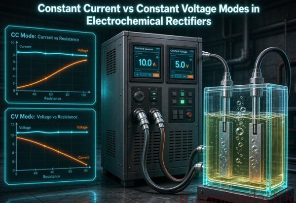
Constant current is the control mode that matches the physics
Since current sets thickness and voltage is a consequence, most plating processes want the rectifier in constant current mode. You set the amps, and the supply raises or lowers its voltage to hold them as the bath changes. Anodizing is the clearest case: the oxide grows, the resistance rises, and the supply walks its voltage up to keep the current flat. Constant voltage mode lets the current drift down as the load changes, which produces a thinner coating than the ampere hour calculation predicted.
Constant voltage still has a place in electrolytic cleaning and some etching steps, where the process is defined by the potential rather than by a deposit. But if the goal is a stated thickness on a stated area, constant current with an ampere hour preset is the control scheme that matches Faraday law.
Ripple is a current specification, not a voltage one
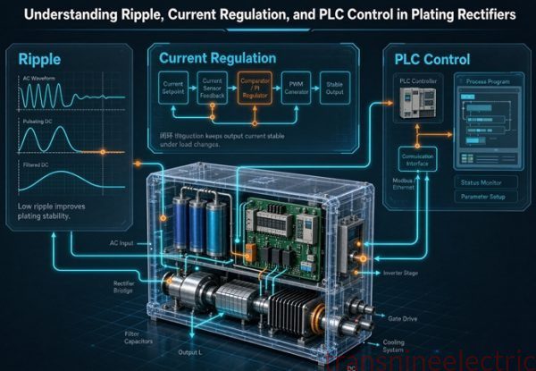
Ripple is the remaining AC wobble on the DC output, expressed as a percent of average current. It matters because every bath has a preferred current density window. When the ripple peak pushes the current above the window you burn the high points. When the trough drops below it the deposit goes porous. The tighter the chemistry, the narrower the window.
The published guidelines cluster tightly. Bright or decorative nickel and decorative chrome want 5 percent or less. Precious metals want 2 to 5 percent or less. General copper tolerates 5 to 10 percent. Basic zinc may be fine up to 10 percent. Hard anodizing wants 3 percent or less, and a precision IGBT unit advertises under 1 percent RMS at rated current. A phase controlled thyristor rectifier typically sits at 5 to 10 percent ripple, which is why a shop can buy an SCR unit for a bright nickel line and then wonder why the finish varies. The supply met the current and voltage numbers and missed the third one.
The ripple frequency itself is arithmetic you can check. A six pulse rectifier on 60 Hz produces 360 Hz ripple, and on 50 Hz it produces 300 Hz. A twelve pulse unit gives 720 Hz and 600 Hz respectively. Higher pulse count does not remove ripple, it moves it to a frequency that is easier to filter. Ask for the ripple percentage at the amperage you will actually run, not at full scale in a data sheet.
Ripple by topology and finish
Put the finish requirement and the topology next to each other and the choice usually makes itself.
| Finish | Ripple limit | Typical topology that meets it | Ripple frequency to filter |
|---|---|---|---|
| Decorative chrome | 5 percent or less | Twelve pulse thyristor or IGBT | 720 Hz at 60 Hz |
| Bright nickel | 5 percent or less | IGBT or filtered SCR | 720 Hz at 60 Hz |
| Precious metals | 2 to 5 percent | Switchmode or IGBT | Higher switching frequency |
| Hard anodize | 3 percent or less | IGBT with output filter | Higher switching frequency |
| General copper | 5 to 10 percent | Six pulse SCR | 360 Hz at 60 Hz |
| Basic zinc | up to 10 percent | Six pulse SCR | 360 Hz at 60 Hz |
A phase controlled thyristor stack typically sits at 5 to 10 percent ripple, which meets the bottom two rows and may miss the top four. Switchmode and IGBT units are advertised under 5 percent and, on precision models, under 1 percent. That is why an SCR unit is a sensible cost effective choice for a heavy zinc or copper line and a questionable one for bright decorative work. The finish sets the ripple limit; the topology either meets it or it does not.
Voltage catalogue step after headroom
Once you have the end of cycle cell voltage and the headroom, pick the next standard rating. The common plating rectifier outputs are 6, 8, 12, 15, 18 and 24 V for low voltage work.
| Cell voltage at worst point | With 20 percent headroom | With 25 percent headroom | Standard unit to order |
|---|---|---|---|
| 6 V | 7.2 V | 7.5 V | 8 V |
| 8 V | 9.6 V | 10.0 V | 12 V |
| 9 V | 10.8 V | 11.3 V | 12 V |
| 12 V | 14.4 V | 15.0 V | 15 or 18 V |
| 18 V | 21.6 V | 22.5 V | 24 V |
| 24 V | 28.8 V | 30.0 V | 30 V special |
The 12 V cell is the awkward one. Twenty five percent headroom lands exactly on 15 V, so an 18 V unit gives comfortable room but a 15 V unit may be enough if your end of cycle voltage is on the low side. This is a conversation to have with the rectifier maker using your actual bath data, not a rule to apply from a table.
The transformer behind the rectifier
Low voltage, high current plating is a strange electrical load. A 12 V, 1000 A rectifier is only 12 kW of DC power, which sounds like a small appliance by industrial standards. But the current is enormous for that power level, and that is exactly what drives the transformer design. The transformer’s job is to step the 480 V or 400 V plant supply down to a secondary voltage that the bridge can turn into those 12 volts, while carrying a current waveform the distribution transformer was never designed for.
Why a 48 kW load needs a 63 kVA transformer
Start with the sizing formula a rectifier transformer maker publishes. The AC apparent power is the DC power divided by three things multiplied together: rectifier efficiency, the form factor of the circuit, and the fundamental power factor. The form factor is the ratio of RMS AC current to average DC current, and it is the number most buyers never ask about. For a six pulse bridge at full firing angle it is about 1.05, and the power factor is about 0.95. Their product is 0.9975, close to one, which is why the result looks almost like the DC power until you add the margins.
Work the plating example. A 24 V, 2000 A DC output is 48,000 W. Divide by 0.97 efficiency, 1.05 form factor and 0.95 power factor and you get 49.6 kVA of AC before any margin. Add 10 percent for harmonic stray losses and you are at 54.6 kVA. The catalogue choice is 63 kVA. Someone who looked only at the 48 kW DC power and ordered a 50 kVA distribution transformer would be short by 9.1 percent even before the harmonics are counted, and the unit would run hot.
The same arithmetic on a 12 V, 1000 A rectifier gives 12.4 kVA base, which is why small plating supplies often sit on a 15 kVA transformer. Note that the voltage label on the rectifier is the DC output, not the transformer secondary. The secondary has to be higher to cover thyristor firing angle, commutation overlap and source impedance.
The low voltage paradox
Push the current to the extreme and the shape of the problem changes. A 12 V, 10,000 A cell is 120 kW, which is still a modest industrial load. But the six pulse line current is 0.8165 times the DC current, about 8,165 A per phase. The secondary line to line voltage needed to make 12 V DC at zero firing angle is Vdc times pi divided by three times the square root of two, which is 8.89 V. In practice the transformer secondary is built for 10 to 14 VAC so there is room for overlap notches and regulation.
At 8,000 A per phase, conductor cross section stops being a cable question and becomes a bus bar question, with 1,000 to 2,000 kcmil copper per phase and bolted joints torqued to the manufacturer’s figure. This is why low voltage rectifier transformers are built with double star windings and interphase reactors rather than as a scaled down distribution transformer. The voltage is tiny, the current is enormous, and the thermal problem sits in the joints and the windings.
Where the volts actually go in a low voltage bus
At 12 V, a loss that would be trivial on a 480 V feeder becomes a large fraction of the output. A plated steel bus bar 10 feet long carrying 8000 A dissipates real power, and that power is lost twice over: once as heat in the bus and again as voltage the rectifier must make up. The transformer secondary voltage is already only 10 to 14 V, so a one volt bus drop is a significant slice.
| Current per phase | Bus resistance | Voltage drop at that current | Power lost as heat |
|---|---|---|---|
| 1000 A | 0.00005 ohm | 0.05 V | 50 W |
| 4000 A | 0.00005 ohm | 0.20 V | 800 W |
| 8000 A | 0.00005 ohm | 0.40 V | 3,200 W |
| 8000 A | 0.00010 ohm | 0.80 V | 6,400 W |
The table uses Ohm law and I squared R with a representative bus resistance; replace it with your measured value before design. The point is the scaling. Doubling current quadruples the heat. Doubling resistance doubles both the drop and the heat. At 8000 A a resistance of 0.0001 ohm eats 6,400 W and 0.8 V of a roughly 9 V secondary, close to 9 percent of the available voltage. That is why the rectifier maker’s advice to keep leads short and contacts clean is not housekeeping, it is a voltage budget item. A loose bolted joint at this current is both a fire risk and a process fault.
Contact resistance is a current problem
The bus table also explains the maintenance advice that appears in every plating rectifier manual. At 1000 A a contact resistance of 0.00005 ohm drops 0.05 V and makes 50 W. The same contact at 8000 A makes 3,200 W in a small area. Oxidation on a copper joint raises that resistance, so a joint that was fine at commissioning can become a hot spot after months in an acid fume environment. Thermographic scans of high current joints are standard practice for a reason. Keep the joints clean, torque them to specification, and recheck them on a maintenance interval, because the voltage you lose there is voltage the bath never sees.
Efficiency is money you can count
The rectifier topology changes the operating cost more than most buyers expect. One manufacturer compares an oil cooled SCR unit at 75 percent efficiency with a water or air cooled IGBT unit at 90 percent on the same 1000 A, 12 V output. Running 6,300 hours a year, the SCR unit draws 100,800 kWh and the IGBT unit 84,000 kWh. The difference is 16,800 kWh a year, or 16.67 percent of the SCR consumption. That is not a claim about brand quality. It is arithmetic from two efficiency figures, and it shows why the question is not just what the rectifier costs to buy.
The same source claims the IGBT unit is about one sixth the volume of the SCR unit for the same DC output. We report that as a vendor claim and do not use it in any calculation. Efficiency percentages, ripple figures and power factor numbers are all published on data sheets and can be checked. Volume ratios and price claims without a model number cannot.
Energy cost scales with current, not with voltage
The 16,800 kWh figure above is for one 12 V, 1000 A unit on 6,300 hours a year. Scale it and the operating cost argument gets clearer. The input power is DC power divided by efficiency, so a lower efficiency hurts most where current is high and the line runs long.
| Rectifier load | DC power | At 75 percent efficiency | At 90 percent efficiency | Saved per year at 6,300 h |
|---|---|---|---|---|
| 12 V, 500 A | 6 kW | 50,400 kWh | 42,000 kWh | 8,400 kWh |
| 12 V, 1000 A | 12 kW | 100,800 kWh | 84,000 kWh | 16,800 kWh |
| 8 V, 2000 A | 16 kW | 134,400 kWh | 112,000 kWh | 22,400 kWh |
| 24 V, 2000 A | 48 kW | 403,200 kWh | 336,000 kWh | 67,200 kWh |
Every figure is DC power divided by the stated efficiency, multiplied by 6,300 hours. The 24 V case saves 67,200 kWh a year, which is four times the saving of the 12 V 1000 A case because it moves four times the DC power. Notice the voltage is the DC output rating; the saving comes from the product of volts and amps. A buyer comparing two quotes on purchase price alone is ignoring a figure that repeats every year the line runs. Multiply the saved kWh by your local tariff to put it in the same currency as the quotation.
The spec line most people forget
A rectifier transformer carries non sinusoidal current. Harmonic currents raise eddy and stray losses in the windings, clamps and tank, so its load loss under real rectifier duty is higher than a sinusoidal factory test would suggest. That is the reason for the 10 to 20 percent harmonic margin in the sizing formula and the reason a standard distribution transformer of the same kVA is not a substitute. Put the pulse count, the form factor, the power factor and the harmonic margin on the transformer line of the RFQ, not just the kVA.
Five things to cross off a quotation
These five showed up in the pages we read or in the arithmetic we believe is missing from them. Each one is checkable in a minute.
| Claim or omission | What the arithmetic says | Consequence |
|---|---|---|
| One 28 row table gives the current for my process | The same 600 L chrome tank is 1500 A by volume and 1000 A by area, a 1.5 times gap | Under or over sizing by 500 A depending on which column you trust |
| A/dm² and ASF are interchangeable | 1 A/dm² is 9.2903 ASF. Chrome at 100 to 200 ASF is 10.76 to 21.53 A/dm² | A current density off by a factor of nine |
| Gold deposits 2.45 g per Ah | That is the trivalent number. Cyanide gold is monovalent at 7.35 g per Ah | A threefold error in precious metal thickness |
| Trivalent chromium gives 0.323 g per Ah | That is the hexavalent number with six electrons. Trivalent needs three and gives 0.6467 | Wrong deposition time and wrong ampere hour preset |
| The rectifier is 12 V, so the transformer is 12 V | At zero firing angle the secondary needs 8.89 V for 12 V DC; in practice 10 to 14 VAC for overlap | A secondary that cannot reach the required DC under load |
Two of those are unit errors. Two are chemistry errors. One is a misunderstanding of what a rectifier voltage rating means. None of them needs a standard to catch.
The source ledger
Here is the evidence ledger for this article. L1 means a primary or near primary document we could read. L2 means a named manufacturer or consultant page with a traceable derivation. L3 means a number we report as a claim but do not use as a requirement.
| # | Source | Grade | What we took | What we did not take |
|---|---|---|---|---|
| 1 | Electroplating reference chapter on Faraday laws | L1 | Equivalent weights, thickness conversion, zinc 0.4555 um/min example | No vendor recommendation |
| 2 | Faraday calculation pages with atomic mass and density tables | L1 | M times 3600 over nF, g/Ah for seven metals | No catalogue ratings |
| 3 | University lecture on deposition from aqueous solutions | L1 | Anode polarization, hydrogen evolution, throwing power by bath class | No equipment data |
| 4 | ScienceDirect papers on trivalent chromium efficiency | L1 | Hydrogen evolution as the dominant competing reaction | No plant sizing data |
| 5 | 28 row process current density and voltage table | L2 | Process values quoted in the table above | Bath chemistry detail |
| 6 | US rectifier maker, area method and ripple guide | L2 | 40 ft² at 25 ASF, headroom, finish ripple limits | Price and brand claims |
| 7 | Plating equipment maker, volumetric method | L2 | A/L figures, 600 L bright nickel 180 A example | The claim it replaces area method |
| 8 | Anodizing consultant guide | L2 | 1.4 safety factor, 60 to 100 V, 3 percent ripple | Cost percentages |
| 9 | IGBT supply data sheet, 60 V 500 A | L2 | Under 1 percent ripple, 30 kW rating | Marketing claims |
| 10 | Rectifier transformer sizing guide | L2 | S equals Pdc over eta kf cosφ, 63 kVA example | Delivery claims |
| 11 | Efficiency comparison on a 1000 A 12 V unit | L2 | 100,800 versus 84,000 kWh, 16,800 kWh saved | One sixth volume claim |
| 12 | Published cost, saving and payback percentages on ranking pages | L3 | Reported as claims only | Not used as requirements |
A copy paste RFQ block
Fifteen lines. Paste them into the enquiry and make every supplier answer each one. The first six settle the process, the next five settle the electrical numbers, and the last four settle the proof.
- State the process and the metal, including the bath chemistry name and supplier.
- State the bath operating temperature range and the allowed tolerance.
- State the largest rack or barrel load, with the exposed part area in dm² or ft².
- State the bare rack area that will carry current and the shape complexity factor used.
- State the required current density in A/dm² or ASF and the source of that number.
- State the target coating thickness, the significant surface, and the minimum thickness point.
- State the calculated current before margin and the headroom percentage applied.
- State the cell voltage at the start and at the end of the cycle, with the larger one marked.
- State the voltage headroom and the resulting rectifier voltage rating.
- State the control mode and whether an ampere hour preset is required.
- State the maximum ripple percent and the current at which it must be met.
- State the rectifier topology, the pulse count and the input phase and voltage.
- State the transformer kVA calculation including efficiency, form factor, power factor and harmonic margin.
- State the cooling method and the enclosure protection against acid or alkali fumes.
- State the test report, the ripple measurement point, the calibration interval and the warranty scope.
Ten facts that belong in different columns
A process number without a condition is not a specification. A standard number without an edition is not a citation. Three things that look similar do three different jobs: a published bath value, a supplier recommendation, and a number you calculated for your own rack. Keep them apart.
| # | Item | Value | Interval or basis | What it is not |
|---|---|---|---|---|
| 1 | Faraday constant | 96,485 C per mol | Basis of every g/Ah figure | Not a rectifier setting |
| 2 | Decorative chrome current density | 10 to 20 A/dm² | 40 to 55 C bath | Not the hard chrome value |
| 3 | Hard chrome current density | 30 to 45 A/dm² | 55 to 60 C bath | Not a voltage rating |
| 4 | Nickel equivalent | 1.095 g per Ah | At 100 percent cathode efficiency | Not the deposit at 95 percent |
| 5 | Hexavalent chromium equivalent | 0.323 g per Ah | Six electrons per atom | Not the trivalent value |
| 6 | Chromium cathode efficiency | 12 to 25 percent | Depends on bath and current density | Not a rectifier loss |
| 7 | Unit conversion | 9.2903 ASF per A/dm² | One dm² is 0.107639 ft² | Not a rounding convenience |
| 8 | Six pulse ripple frequency | 360 Hz at 60 Hz | Pulse count times line frequency | Not the ripple percentage |
| 9 | Rectifier transformer example | 54.6 kVA before catalogue rounding | 24 V times 2000 A with margins | Not equal to 48 kW DC |
| 10 | Date of this article | November 16, 2026 | 1,564 days after August 2022, carried over from earlier work | Not a standard publication date |
Rows 6 and 10 carry the most caution. Cathode efficiency is a property of the bath at a given current density, temperature and additive package, and no rectifier data sheet can guarantee it. The date in row 10 is this article’s research date, not the publication date of any standard cited here. We did not re verify the edition dates of IEEE 519, AMS 2469 or MIL A 8625 for this piece, and none of them changes a Faraday calculation.
Bring this to the specification meeting
The whole answer in one place
If you have five minutes, say this. Current comes from surface area times the current density of the bath, then add headroom. Forty square feet at 25 ASF is 1000 A, and 15 percent margin takes you to 1150 A and a 1200 A unit. Thickness follows Faraday law: one ampere hour deposits 1.095 g of nickel or 0.323 g of chromium at full efficiency, and at 13 percent cathode efficiency the real chromium number is about 0.042 g. Voltage is not a target, it is what the bath needs at the worst point in the cycle, so use the end of cycle voltage for anodizing and add 20 to 25 percent headroom. Decorative chrome at 7 to 9 V lands on a 12 V supply after margin; hard anodize at 50 to 130 V is a different class of machine. Ripple is a current specification measured at the amperage you run, and bright nickel wants 5 percent or less. The transformer is sized from DC power divided by efficiency, form factor and power factor: 24 V at 2000 A ends at 54.6 kVA after harmonic margin, so you order 63 kVA. Put the process, the area, the current density, the end of cycle voltage, the ripple limit and the transformer assumptions on six separate lines.
That is the whole article in one paragraph. Everything else here is the evidence for one of those sentences.
What actually costs money is what sits between the lines. A 600 L chrome tank is 1500 A by the volumetric rule and 1000 A by the area rule. A US ASF table and a supplier A/dm² table describe the same chrome process with numbers that look unrelated until you multiply by 9.2903. Hexavalent and trivalent chromium differ by a factor of two in grams per ampere hour. A phase controlled rectifier at 5 to 10 percent ripple can quietly fail a bright nickel finish that met every current and voltage number. A 48 kW DC load needs a 63 kVA transformer. Six of these are document failures, not chemistry failures, and every one is catchable with a line on an RFQ before the order is released.
Twelve numbers worth keeping
| Number | What it decides |
|---|---|
| 9.2903 | ASF per A/dm², the conversion that reconciles the US and supplier tables |
| 1000 A | 40 ft² times 25 ASF, before margin |
| 1150 A and 1200 A | 1000 A plus 15 percent, and the catalogue choice |
| 1500 A versus 1000 A | The 600 L chrome tank by volume versus by area |
| 1.095 and 0.323 g/Ah | Nickel and hexavalent chromium equivalents at full efficiency |
| 0.042 g/Ah | Chromium at 13 percent cathode efficiency |
| 24.75 times | Nickel versus chromium mass for the same 1000 Ah |
| 17.08 um/Ah/dm² | Zinc thickness per ampere hour per square decimetre |
| 0.4555 um/min | Zinc growth at 2.0 A/dm² and 80 percent efficiency |
| 8.56 Ah | Nickel required for 10 um on 10 dm² at 95 percent efficiency |
| 49.6 and 54.6 kVA | Rectifier transformer before and after 10 percent harmonic margin |
| 16,800 kWh | Annual saving going from 75 to 90 percent efficiency at 12 V 1000 A |
Keep 9.2903 for the moment a supplier quotes ASF and your bath sheet quotes A/dm². Keep 1000 and 1150 A for the current conversation. Keep both chrome numbers for the two method argument. Keep the equivalents and 24.75 for the why chrome is slow conversation. Keep 0.4555 and 8.56 for the thickness and cycle time conversation. Keep the two kVA figures for the transformer order and 16,800 kWh for the operating cost conversation.
Those numbers fit on one page of a bid review, and each one is recomputable from figures printed in this article. If you have a bath data sheet, a drawing with the rack area, two quotations and a nameplate photo, send them over. We will tell you which current method each supplier used, whether the voltage covers the end of the cycle, whether the ripple limit fits the finish, and which of the fifteen RFQ lines still need an answer before you release the order. Start here.
FAQ
Which comes first, the amps or the volts?
The amps. Current sets deposit thickness by Faraday law and comes from surface area times current density. Voltage is whatever the bath needs to push that current. Size current first, then pick a voltage rating with 20 to 25 percent headroom above the end of cycle requirement.
How do I calculate rectifier amps for a plating rack?
Multiply the exposed surface area by the bath current density. Forty square feet at 25 ASF gives 1000 A. Add 10 to 20 percent margin, so a 1150 A requirement lands on a 1200 A unit. Count both sides of sheet metal and the bare rack area, or the result will be low.
What does one ampere hour deposit?
It depends on the metal. One Ah deposits 1.095 g of nickel, 1.186 g of copper, 1.220 g of zinc and 0.323 g of hexavalent chromium at 100 percent efficiency. Multiply by cathode efficiency for the real mass, and remember chromium runs at about 13 percent.
Why does chrome need more current than nickel?
Hexavalent chromium needs six electrons per atom, so its equivalent is 0.323 g per Ah against nickel’s 1.095. Most current goes to hydrogen instead of metal at roughly 13 percent efficiency. For the same 1000 Ah, nickel deposits about 24.75 times more mass.
What voltage does decorative chrome need?
The bath draws 7 to 9 V at 40 to 55 C. Add 20 to 25 percent headroom and the requirement is 8.4 to 11.3 V, so a 12 V rectifier is the normal choice. The voltage rating is a ceiling, not the value you set the process to run at.
What voltage does hard anodizing need?
Published ranges are 40 to 75 V, 50 to 130 V and 60 to 100 V depending on alloy and coating. Size from the end of the cycle when the oxide is thickest. A 12 V 500 A unit is 6 kW; a 60 V 500 A unit is 30 kW at the same current.
How many ASF is 20 A/dm²?
185.81 ASF. One A/dm² is 9.2903 ASF because one dm² is 0.107639 ft². Decorative chrome quoted as 100 to 200 ASF is 10.76 to 21.53 A/dm², which matches the 10 to 20 A/dm² process table.
What is cathode efficiency and where do I get it?
It is the fraction of current that actually deposits metal, and the rest goes to hydrogen or side reactions. Nickel runs 93 to 97 percent, zinc 90 to 98 percent, hard chrome 12 to 25 percent. Get it from your bath supplier’s data sheet, not from a rectifier catalogue.
How long does 10 micrometres of nickel take?
On 10 dm² at 95 percent efficiency, 10 um of nickel needs 8.56 Ah. At 4 A/dm² that is 40 A, so the cycle takes about 12.8 minutes. Use an ampere hour preset rather than a timer if the current drifts during the run.
What ripple does bright nickel need?
5 percent or less, measured at the current you will actually run. General copper tolerates 5 to 10 percent, basic zinc up to 10 percent, precious metals 2 to 5 percent, and hard anodize 3 percent or less. A six pulse SCR unit at 60 Hz has 360 Hz ripple.
Why is my 48 kW plating line ordered with a 63 kVA transformer?
Because 24 V at 2000 A is 48 kW of DC, but the AC apparent power is 48 divided by 0.97 efficiency, 1.05 form factor and 0.95 power factor, which is 49.6 kVA. Add 10 percent harmonic margin for 54.6 kVA and the catalogue step is 63 kVA.
Can I use the litres-of-bath method instead of surface area?
You can, but check both. The same 600 L chrome tank is 1500 A at 2.5 A/L and 1000 A at 100 A/dm² on 10 dm² of work, a factor of 1.5. Volume limits what the chemistry can carry; area sets what the work needs. Use the larger figure and verify the bath can take it.
What should the RFQ say?
Fifteen lines: process and chemistry, temperature, largest load and area, bare rack area, current density and its source, thickness target, current with headroom, start and end voltage, voltage headroom of 20 to 25 percent, control mode, ripple limit at the running current, topology and pulse count, transformer kVA assumptions, cooling and enclosure, and the test report.