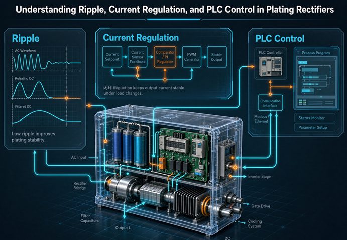
In a plating rectifier, ripple is the unwanted AC left in the DC output, current regulation is how tightly the unit holds your set current as the bath changes, and PLC control is what lets it follow your line’s ramp recipes and alarms automatically. Miss any one and deposit thickness drifts, rejects climb, and chemistry is wasted.
At a glance
- Plating deposit thickness is set by current × time (Faraday’s law) — so the current has to stay put.
- Ripple under 5% is fine for most plating; bright nickel, hard chrome, and PCB work usually want under 2–3%.
- Current regulation of ±1% is the common baseline; ±0.5% is the precision tier.
- PLC control turns the rectifier into a line citizen: recipes, soft start, amp-hour dosing, alarms, remote setpoint.
- Most lines talk over 4–20 mA, 0–10 V, RS-485 Modbus, Profibus, or EtherNet/IP.
The short version
Most people shop a plating rectifier by amps and volts. That’s the easy part. The part that actually bites you later is the quality of the DC and how the box behaves on a real line. Three things separate a rectifier that just makes DC from one that makes repeatable DC:
- Ripple — the leftover AC wobble in your “DC.” Too much of it and the deposit gets grainy, brittle, or striped.
- Current regulation — how well the unit holds your set amperage when the bath fights back (resistance changes, temperature drifts, parts go in and out).
- PLC control — whether the rectifier can take orders from your line controller instead of needing a human at the knob for every rack.
Get those three right and the salt-spray test stops being where you find out the coating was bad. Get them wrong and you find out at the salt-spray test — after the parts are already shipped.
Why plating is a current-control problem first
Faraday’s law in one line
The amount of metal laid down in electroplating is, to a first approximation, a direct function of current × time. Push more amps, or push them longer, and more metal lands on the part. That’s it. The voltage is just the means to push the current through the bath.
What happens when the current wanders
Here’s the trap: as a rack drops into the tank, the effective resistance changes. As the bath warms up over a shift, it changes again. If your rectifier is holding voltage steady but the current is free to move, the deposit thickness moves with it — and you won’t see it until the finish is measured or the part fails. A plating rectifier is therefore first a current regulator and only incidentally a power supply. The regulation spec is not a nice-to-have; it’s the whole point.
Ripple — the AC you didn’t ask for
What ripple actually is
Perfect DC is a flat line. Real rectifier output is a flat line with a small AC sawtooth riding on top. Ripple is that sawtooth, expressed as a percentage of the DC level (usually RMS). A “5% ripple” unit puts 5 amps of AC wobble on every 100 amps of DC.
Where ripple comes from
A thyristor (SCR) rectifier regulates by firing at an angle in each half-cycle, so its output always carries ripple at multiples of the line frequency. On a 60 Hz supply, a 6-pulse unit puts ripple around 360 Hz; a 12-pulse unit pushes the dominant component to 720 Hz. That’s why multi-pulse transformer windings (covered in our phase-shift write-up) and output filters matter — they knock the ripple down at the source.
A switch-mode (IGBT) rectifier is different. It chops at tens of kilohertz and filters hard, so ripple typically lands at 1–2% or lower. You pay more per amp and the electronics are fussier to service, but the waveform is clean. For precious metals and fine PCB traces, that cleanliness is often worth it.
How much ripple is too much
This is the table most spec sheets skip. The acceptable number depends entirely on what you’re plating:
| Process | Typical ripple target | Why it matters |
|---|---|---|
| Decorative nickel / zinc | Under 5% | Roughness becomes visible above this |
| Bright nickel | Under 2–3% | Grain structure and brightness |
| Hard chrome | Under 1–3% (often <2%) | Avoids “ripple banding” striations |
| PCB / precious metals | Under 1–3% | Fine traces, uniform deposition |
| Anodizing (decorative) | Under 5% | Generally acceptable |
| General functional plating | Under 5% | Baseline for most job shops |
These are typical industry ranges, not absolute limits. Your chemistry and thickness tolerance set the real bar — confirm with your plating engineer before you write the spec.
The hard-chrome “ripple banding” trap
This one deserves its own line. In hard chrome, too much ripple produces ripple banding — visible light-and-dark striations in the deposit where the current density oscillates. It looks like tree rings on the part. Specifying under 3%, and often under 1–2%, is the usual fix. A lot of “my chrome looks weird” calls trace straight back to a rectifier that was bought on price with no ripple number on the datasheet.
Current regulation — holding the setpoint
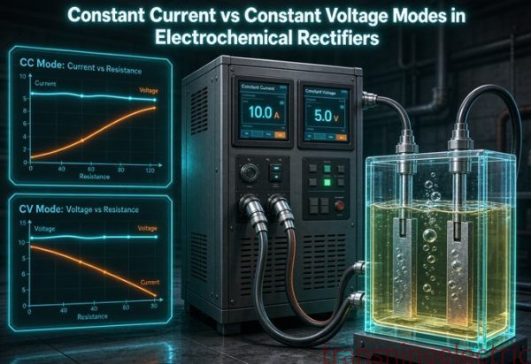
Constant current vs constant voltage (CC vs CV)
Most plating wants constant current (CC): you set the amps, and the rectifier adjusts its voltage to keep that current steady as the load changes. Constant voltage (CV) holds the volts and lets the amps float — fine for a few specialized processes, wrong for almost everything in a plating shop. If a supplier defaults your quote to CV, push back. For plating, CC is the safe assumption unless your process sheet says otherwise.
What ±1% or ±0.5% really buys you
Regulation accuracy tells you how far the actual current can drift from your set point under changing line and load conditions. ±1% is the common industrial baseline and is plenty for most lines. ±0.5% (or better) is the precision tier for precious metals, PCB, and tight-tolerance hard chrome. One catch: that number is usually quoted at rated load. Ask how it behaves at the low end, too, because an SCR unit running at 20% of nameplate can regulate and ripple worse than at 100%.
PLC control — turning a rectifier into a line citizen
What the PLC actually does for you
A bare rectifier is a box with a knob. A PLC-controlled rectifier is a node on your line. Concretely, the PLC lets you:
- Soft start / ramp — ease the current up on immersion so you don’t gas the part or shock the bath.
- Recipes — store a current profile per part type and switch with one command instead of re-dialing.
- Ampere-hour totalizing — count the actual amp-hours through the tank so your chemistry dosing tracks real work, not a guess.
- Alarms and interlocks — over-current, over-temp, phase loss, earth leakage, and line faults get caught and reported.
- Remote setpoint and readback — the line controller sets and verifies output without a person at the panel.
For a job shop running mixed work, recipes and amp-hour totalizing alone usually pay back the PLC option in months through less scrap and tighter dosing.
The interface standards that matter
You don’t need to be a controls engineer to buy this right — you need to match what your line already speaks:
| Interface | Type | What it’s for |
|---|---|---|
| 4–20 mA | Analog | Simple remote setpoint and readback |
| 0–10 V | Analog | Alternative analog control |
| RS-485 Modbus RTU | Digital serial | Recipes, polling, multiple rectifiers |
| Profibus DP | Digital fieldbus | Older European lines |
| EtherNet/IP | Digital fieldbus | Modern Industry 4.0 lines |
| HMI touchscreen | Local panel | Operator control and recipe storage |
If your main line controller is a Siemens or Rockwell PLC, say so up front — that decides whether Profibus or EtherNet/IP is the natural fit. As this guide notes, a rectifier the PLC can’t talk to is a rectifier you’ll fight with on every changeover.
Remote setpoint and line integration
The practical win is that the line controller becomes the brain. It tells each rectifier when to start (rack in the tank), what current to hold (based on the rack’s area), and when to stop. On a high-speed line doing 8 meters per minute, that real-time response is the difference between consistent coating and edge-burnt parts. The rectifier just has to listen well.
How the three fit together
Here’s the mental model that ties the keyword together: ripple is the purity of your DC, current regulation is the steadiness of your DC, and PLC control is the repeatability of your DC across every rack and every shift. A unit can have low ripple and still drift if the regulation is loose. It can regulate perfectly and still need a human on every part if there’s no PLC. And it can have a great PLC and still make ugly chrome if the ripple number is buried in the fine print. You’re really buying one outcome — deposit that repeats — and these three are the levers.
Common mistakes buyers make
Mistake 1: specifying CV for a plating job
Voltage regulation is cheaper to claim and easier to sell, but plating needs current regulation. If the quote says “CV” by default, ask for CC. Your deposit thickness depends on it.
Mistake 2: ignoring ripple on chrome or PCB
“It’s a rectifier, DC is DC” is a costly assumption. On hard chrome and PCB, ripple shows up as banding or uneven traces. Put a ripple number in the spec or you’ll be debugging the finish later.
Mistake 3: oversizing and living with worse ripple
Buying a 25,000-amp unit to run 10,000 amps “for future growth” sounds safe, but an SCR unit at the low end of its range often regulates and ripples worse. Size to the real load with a sane margin, not to a dream capacity.
Mistake 4: buying a rectifier the PLC can’t talk to
A standalone box with a local knob on a modern automated line means a person walking to every tank. Confirm the communication interface before you buy, not after the panel is wired.
What to put in your RFQ
A spec line that actually gets you the right unit looks like this:
- Process: e.g. hard chrome, bright nickel, PCB copper
- Max DC current / voltage: e.g. 5,000 A at 24 V
- Ripple target: e.g. under 3% (under 2% for chrome)
- Regulation class: e.g. ±1% CC (±0.5% if precision)
- Control mode: CC (constant current)
- Communication: e.g. RS-485 Modbus + 4–20 mA
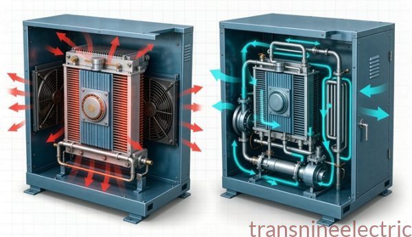
- Cooling: air or water (driven by current and ambient)
- Extras: periodic reverse, amp-hour totalizing, N+1 redundancy
Add your bath and rack area and a good supplier will size it instead of guessing — which usually beats both oversizing and undersizing.
Frequently asked questions
What is an acceptable ripple for a plating rectifier?
For most decorative and functional plating, ripple under 5% of the DC output is fine. Bright nickel, hard chrome, and PCB or precious-metal work usually call for under 2–3%, and some hard-chrome lines want under 1–2% to avoid ripple banding. Above roughly 10% you will see it in the finish as a grainy or striated deposit.
Does a plating rectifier need constant current or constant voltage?
Plating almost always needs constant current (CC). The bath resistance changes as parts enter the tank, temperature shifts, and the deposit builds, so a fixed voltage would let the current wander and the coating thickness would vary. A constant-current rectifier holds the amps while the load changes. Constant voltage (CV) is the right mode only for a few specialized processes where voltage is the controlled variable.
How does a PLC control a plating rectifier?
The PLC sends a setpoint to the rectifier over a standard interface (commonly 4–20 mA or 0–10 V analog, or RS-485 Modbus, Profibus, or EtherNet/IP digital). It triggers soft start or ramp profiles, switches stored recipes per part type, reads back actual current and voltage, runs ampere-hour totalizing for chemistry dosing, and raises alarms on faults. The rectifier stays a line citizen instead of a standalone box.
Why is ripple worse on a thyristor (SCR) rectifier than a switch-mode unit?
A thyristor rectifier regulates by phase-angle firing, so its DC carries an AC ripple at multiples of the line frequency (a 6-pulse unit puts ripple around 360 Hz on a 60 Hz supply; 12-pulse pushes it to 720 Hz). A switch-mode (IGBT) rectifier chops at 20–100 kHz and filters it down, so ripple typically lands at 1–2% or lower. Multi-pulse transformer windings and output filters are the usual ways to cut SCR ripple.
What current regulation accuracy should I specify?
Plus or minus 1% of the set value is the common industrial baseline and is good enough for most lines. If your process is sensitive (precious metals, PCB, hard chrome), ask for plus or minus 0.5% or better. Remember the number is usually stated at rated load; check the low-end behavior too, because regulation and ripple both soften when you run an SCR unit far below its nameplate current.
What control interface should the rectifier have for my line?
Match what your line already speaks. Analog 4–20 mA or 0–10 V covers simple remote setpoint and readback. RS-485 Modbus RTU is the workhorse for recipes, polling, and running several rectifiers together. Profibus DP still appears on older European lines; EtherNet/IP is the modern Industry 4.0 choice. Also confirm a local HMI for the operator. As this guide notes, a rectifier the PLC cannot talk to is a rectifier you will fight with.
What should I put in my RFQ for a plating rectifier?
State the process (e.g. hard chrome), max DC current and voltage, the ripple target (e.g. under 3%), the regulation class (e.g. plus or minus 1% CC), the control mode (CC/CV), the communication interface (e.g. RS-485 Modbus, 4–20 mA), cooling (air or water), and any extras like periodic-reverse, ampere-hour totalizing, or N+1 redundancy. Giving the bath and rack area helps the supplier size it instead of guessing.