If you are comparing rectifiers and the spec sheet says “CC/CV,” you have probably hit the same confusion every buyer hits. Salespeople tend to say “it does both” and move on. But the two modes behave very differently in a real tank, and picking the wrong one shows up as thickness drift, burnt parts, or a batch that fails inspection. This guide breaks down what each mode really does, which one belongs on your process, and how to specify a unit so you are not the one paying for the lesson.
The one rule that decides almost everything
Before we compare modes, lock in a single fact, because it explains roughly 80% of the decision. Electrodeposition is governed by Faraday’s law of electrolysis:
m = M × I × t × η / (n × F)
where m is the mass deposited, M the metal’s molar mass, I the current, t the time, η the current efficiency, n the electrons transferred per ion, and F the Faraday constant (96,485 C/mol, often rounded to 26.8 Ah/mol). Notice what is missing: voltage. Voltage is the push; current is what actually moves metal.
That has a practical consequence. If you want a predictable deposit, you control the current and the time. Hold the amps steady and your deposition rate is steady, regardless of what the bath resistance does in between. Hold the volts steady instead, and any drift in resistance quietly changes the current, and therefore the thickness.
Quick sense check: at 100% efficiency, one amp-hour deposits about 1.19 g of copper, 1.10 g of nickel, or 4.02 g of silver, but only about 0.32 g of hexavalent chromium, because Cr(VI) needs six electrons per atom. That is why a chrome line needs far more time (or current) for the same mass.
CC vs CV at a glance
| Aspect | Constant current (CC) | Constant voltage (CV) |
|---|---|---|
| What is held steady | Output current (amps) | Output voltage (volts) |
| What floats | Voltage, within a compliance ceiling | Current, up to the current limit |
| Governing limit | Maximum voltage (compliance) | Maximum current (current limit) |
| Controls deposition rate | Yes, directly (via amp-hours) | Indirectly, and only while resistance is stable |
| Reaction to rising bath resistance | Raises voltage to keep amps fixed | Current falls as I = V / R |
| Typical use | Rack/barrel plating, electrowinning, electrolysis, stage 1 of anodizing | Electrocoating, electropolishing, stage 2 of anodizing, current-limited supplies |
| Main risk if misapplied | Hits voltage ceiling and silently stops regulating | Thickness drifts as temperature or area changes |
How each mode actually works
Constant current mode
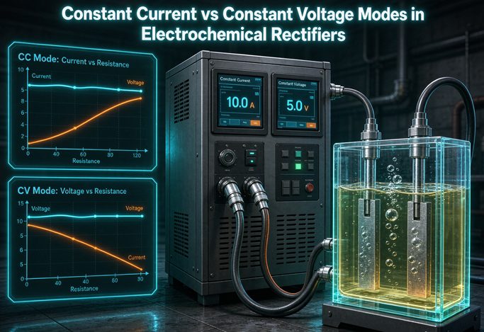
In CC mode the rectifier measures its output current, compares it with the reference you dial in (the “amps” setpoint), and continuously adjusts output voltage until the measured current matches. It holds that current as long as the voltage it needs stays below the unit’s maximum, called the compliance voltage. Think of it as a current source that will push whatever voltage is necessary, within limits, to keep the same amps flowing.
This is why CC naturally protects thickness. When a rack of parts enters the tank and bath resistance shifts, the loop moves the voltage to compensate, so the current barely blips. The faster the loop, the shorter the blip, and the more uniform the deposit across the rack.
Constant voltage mode
CV mode does the mirror image. It measures output voltage, compares it with your volts setpoint, and adjusts output until the two match. Current is then whatever the load draws, I = V / R, up to the current limit. Once the load tries to pull more than that limit, the supply gives up on holding voltage and drops into CC to protect itself.
CV is genuinely useful when the process wants a fixed electrical potential, or when the growing coating is meant to self-limit. Electrocoating and electropolishing are the classic cases: the film or the dissolution reaction is potential-dependent, so pinning the voltage is the whole point.
The crossover point, without the mystery
Every CC/CV supply has a boundary between the two modes. It is set by the critical (or compliance) resistance:
Rc = Vset / Ilimit
If the load resistance RL is greater than Rc, the supply runs in CV: voltage is held at setpoint and current stays below the limit. If RL falls below Rc, it runs in CC: current is held at the limit and voltage drops below setpoint.
Worked example: set 30 V and a 5 A limit, so Rc = 6 Ω. Attach an 8 Ω bath and you are in CV, drawing 30/8 = 3.75 A. Drop to 4 Ω (more parts, warmer bath, higher conductivity) and 30/4 would be 7.5 A, above the limit, so the unit crosses into CC and holds 5 A at 20 V. Understanding this line is the difference between “it does both modes” and actually knowing what your rectifier is doing at 2 a.m. on a production run.
Why bath resistance is the real decision variable
Here is the question that cuts through the marketing: does the resistance of your load stay roughly constant during the cycle, or does it move a lot?
In a rack plating line with a fixed part area and a well-controlled bath, resistance is fairly stable, so either mode can hold the setpoint. CC still wins because it ties deposition directly to amp-hours. In processes where resistance climbs or falls significantly, the choice matters much more:
- Rising resistance (oxide thickening in anodizing, paint film building in electrocoating): under CV, current would collapse as the layer grows. Under CC, voltage climbs to push the same current, keeping growth rate steady until a voltage ceiling is reached.
- Falling resistance (parts added, bath heated, concentration increased): under CV, current surges and can burn parts. Under CC, voltage simply backs off and the current stays put.
- Changing part area (continuous strip, mixed loads): the ideal is true constant current density, where the supply adjusts current as area changes. If that is not available, CC is right when area is fixed; when area varies widely, some operators accept CV as a compromise. There is no free lunch here, and a supplier who promises otherwise is selling a fantasy.
Honest caveat: no mode compensates for bad current distribution. Throw power, rack contact resistance, and part geometry still decide whether the recess gets half the coating the edge gets. A rectifier holds the setpoint; it cannot rewrite physics inside the tank.
Which mode for which process
| Process | Usual mode | Why | Typical voltage |
|---|---|---|---|
| Rack / barrel plating (Zn, Ni, Cu, decorative Cr) | CC | Fixed area; steady amps give steady thickness and current density | 6–12 V |
| Hard chrome plating | CC, low ripple | Thickness control and efficiency are current-driven; ripple must stay low | 8–24 V |
| Precious metal / PCB plating | CC, very low ripple | Tight thickness tolerance, fine grain; ripple under ~2% | 6–12 V |
| Electrowinning / electrorefining | CC | Output mass is proportional to current; many cells in series | Varies, often low per cell |
| Chlor-alkali / water electrolysis | CC | Hydrogen or chlorine output tracks current (Faraday) | Varies by cell stack |
| Aluminum anodizing (Type II / hard coat) | CC → CV crossover | CC grows a uniform film; CV caps voltage to stop burning | 0–20 V / 0–60 V |
| Electrocoating (electrophoretic painting) | CV | Film is potential-driven and self-limiting as resistance rises | 0–500 V range typical |
| Electropolishing / electrocleaning | CV | Requires a controlled potential window for selective dissolution | Varies |
| Micro-arc oxidation (MAO / PEO) | Pulsed, CC-controlled | Needs high voltage breakdown and controlled current density | Up to hundreds of volts |
Values are typical industry ranges, not universal limits. Confirm against your bath chemistry and process data sheet before specifying.
The anodizing contradiction, settled
If you have been googling this, you have probably found conflicting answers. One supplier says “anodizing must be constant current.” Another says “use constant voltage for anodizing.” Both are partially right, which is exactly why the advice feels useless.
Here is what actually happens in an aluminum anodizing tank. At the start, the part is bare and conductive. You want a specific current density (for sulfuric acid Type II, often in the range of roughly 10–20 ASF) to grow the barrier and porous oxide layer evenly. That calls for CC: hold the amps, let voltage be whatever it needs to be.
As the oxide thickens, it is an insulator, so cell resistance climbs and the voltage rises steadily to keep the same current. Left unchecked forever, the voltage would climb until the coating burns, pits, or heats the part. So the rectifier has a voltage ceiling. When the rising voltage reaches it, the unit automatically crosses over to CV: voltage now holds at the ceiling, and the current naturally tapers off as the film finishes growing. The result is a uniform, self-limited film with no thermal damage.
So the correct answer is a two-stage CC-to-CV profile, and a rectifier with automatic, clean crossover is what you want. Ask the supplier to show you the crossover behavior and where you set that ceiling. If they cannot explain it, keep shopping.
Buyer tip: hard coat anodizing runs colder and at higher current density, and the voltage ceiling is higher (hard coat units are often specified around 0–60 V, versus 0–20 V for standard sulfuric anodizing). Do not reuse a standard anodizing setpoint on a hard coat line.
What to look for on the spec sheet
Two rectifiers can both claim “CC/CV” and behave nothing alike. These are the lines that separate them.
Regulation accuracy
Traditional SCR (thyristor) phase-controlled units typically land around ±1–2%. High-frequency switch-mode units are commonly ±0.5%, and precision designs claim ±0.1%. For decorative work the difference may not matter; for semiconductor lead frames or precious metal plating it directly affects yield.
Ripple, and how it was measured
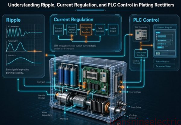
Ripple is the residual AC sitting on your DC. General industrial plating can tolerate a few percent; hard chrome, precious metals, and semiconductor work often want under 2%. But a single percentage is meaningless on its own. Always ask at what load and at what ripple frequency it was measured. The electrode surface has a double-layer capacitance; at low ripple frequencies that capacitance has time to discharge between cycles, so the effective potential follows the instantaneous current. At high frequencies it does not, and the deposit stays closer to the average. That is why a high-frequency unit can produce a denser, finer deposit than an SCR unit with the same stated ripple number.
Loop response speed
In an SCR rectifier the control loop can only update once per half cycle of the mains. A high-frequency unit can update every switching cycle, a difference of roughly two orders of magnitude. When a rack drops into the tank and resistance changes almost instantly, the slow unit lets the current dip before correcting; the fast one catches it. That brief dip is exactly where thickness variation across the rack begins.
Compliance voltage, ramping, and amp-hour integration
- Compliance voltage: the voltage ceiling a CC unit will allow. If bath resistance pushes the required voltage above it, the unit stops holding current. Make sure it comfortably covers your worst-case resistance.
- Soft start / ramp: lets you ease current up at the start to avoid shocking the workpiece and fixtures. Standard on decent anodizing units.
- Amp-hour / amp-minute integrator: the practical tool for Faraday-based thickness control and batch-to-batch repeatability.
- Communications: RS485 / Modbus RTU, 0–10 V or 4–20 mA inputs, and increasingly Ethernet or Profibus for PLC and SCADA integration and traceability.
Five mistakes that quietly wreck batches
- Trying to control thickness with voltage. Thickness follows amp-hours. An amp-hour integrator plus CC will beat a voltmeter every time.
- Ignoring compliance voltage. A CC unit whose voltage ceilings out mid-cycle is not actually holding current. Verify the ceiling against your highest-resistance condition.
- Comparing ripple numbers without measurement conditions. Load and frequency change the story. Ask for both.
- Buying with zero headroom. Size current from area × current density, then add 20–30%. Undersizing is a far more common failure than oversizing.
- Assuming “auto CV/CC” means it handles your process. Automatic crossover is a tool, not a process recipe. Get the setpoints and the transition behavior in writing.
RFQ checklist: copy this into your next inquiry
The fastest way to get a useless quote is to ask for “a rectifier, 1000 A.” Give the supplier these inputs and you will get a unit that fits the tank:
- Process type (rack plating, hard chrome, anodizing, electrowinning, electrolysis, electrocoating, etc.)
- Bath chemistry and your process data sheet
- Required DC current range and voltage range, and how each varies during the cycle
- Control modes needed: CC, CV, pulse, reverse pulse, ramp, multi-stage profile
- Duty cycle and the current/voltage ramp profile
- Ripple limit, plus how it should be measured
- Mains supply voltage, frequency, phase, and available short-circuit level
- Harmonic limits at the point of common coupling (for example, IEEE 519 targets)
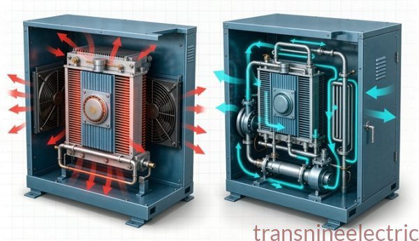
- Cooling (forced air or water) and cooling-water quality or ambient conditions
- Installation environment: corrosive atmosphere, IP rating, altitude
- DC busbar route and distance to the cells
- Metering, data logging, and communications protocol
- Quantity and spare-parts expectations
Standards worth naming in the inquiry include IEC 60146 for semiconductor power converters and IEEE 519 where grid harmonics are governed. Confirm the current editions with your supplier before contract signature.
FAQ
Which mode should I use for electroplating, constant current or constant voltage?
For most rack and barrel electroplating, use constant current. Deposited metal mass follows Faraday’s law, meaning it is proportional to current × time, so holding the amps steady holds your deposition rate and thickness steady even as bath resistance drifts. As explained above, that is why CC is the default on a plating line.
Is anodizing done in constant current or constant voltage mode?
Both, in sequence. Start in constant current to grow the oxide layer at a controlled current density, then let the rectifier cross over to constant voltage once it hits the set voltage ceiling. That two-stage CC-to-CV profile grows a uniform film and then caps voltage to prevent burning.
What is the crossover point between CV and CC?
It is the load resistance where the supply stops regulating voltage and starts regulating current. It equals the set voltage divided by the set current limit (Rc = Vset / Ilimit). Above Rc the unit runs in CV; below it, in CC.
What is compliance voltage and why does it matter in CC mode?
Compliance voltage is the maximum voltage the rectifier will allow while trying to hold a set current. If bath resistance rises enough that the needed voltage exceeds this ceiling, the supply can no longer hold the current and effectively falls out of CC. Always check it on a CC unit.
Why does my plating thickness vary even with a constant voltage power supply?
Because thickness follows amp-hours, not volts. Under constant voltage, current equals voltage divided by bath resistance, so any change in temperature, concentration, or part area changes the current and therefore the deposition rate. An amp-hour integrator and CC operation make thickness repeatable.
How much ripple is acceptable on an electrochemical rectifier?
General industrial plating tolerates a few percent; precious metals and semiconductor work usually call for under 2%. Always ask at what load and ripple frequency the number was measured, because frequency changes how the deposit forms even at the same measured percentage.
How do I size a rectifier for a plating tank?
Size by current first: total amps equal the parts’ total surface area times the required current density, then add a 20–30% margin. Voltage is usually modest, around 6–12 V for most immersion baths. 1 ASD equals 1 A/dm².
What information should I send when requesting a rectifier quote?
Send the process type, required DC current and voltage range, how they vary, the control modes needed, duty cycle and ramp profile, mains supply and harmonic limits, cooling and installation conditions, ripple limits, communications protocol, and quantity. The checklist above is copy-ready.