A Canadian building runs on 600Y/347 V because 600 V is the highest voltage that still counts as low voltage under the Canadian code, and 347 V is its line to neutral. One transformer lights the building, turns the motors, and brings out a neutral. The 25 kV delta primary is the utility’s three wire habit.
| kVA | Primary amps at 24,940 V | 150 percent fuse threshold | Secondary amps at 600 V | 125 percent conductor | Fault current at 600 V, 5.75 percent |
|---|---|---|---|---|---|
| 500 | 11.57 | 17.36 | 481.1 | 601.4 | 8,367 |
| 750 | 17.36 | 26.04 | 721.7 | 902.1 | 12,551 |
| 1,000 | 23.15 | 34.72 | 962.3 | 1,202.8 | 16,735 |
| 1,500 | 34.72 | 52.09 | 1,443.4 | 1,804.2 | 25,102 |
| 2,000 | 46.30 | 69.45 | 1,924.5 | 2,405.6 | 33,470 |
| 2,500 | 57.87 | 86.81 | 2,405.6 | 3,007.0 | 41,837 |
| 3,000 | 69.45 | 104.17 | 2,886.8 | 3,608.5 | 50,204 |
Nothing in that table is a rule of thumb. Every column is one division, and the divisions are the subject of this article, because the Canadian answer to “why this configuration” is not a tradition. It is a set of equipment boundaries that happen to land on 600 and 347, and a set of code rules that are different from the ones a US reader will bring to the page.
The configuration in three numbers
A nameplate on one of these units reads something like 2,500 kVA, 24940 V delta, 600Y/347 V, 5.75 percent, Dyn1, 65 degree rise, ONAN. Five of those fields are familiar to anyone who buys transformers. Two of them are not, and they are the two that explain the whole practice.
24,940 is the real primary voltage
There is no 25 kV distribution system in Canada. There is a 25 kV class, and inside that class the nominal voltage is 24.94 kV. EPCOR’s interconnection requirements list its three distribution levels as 4.16, 13.86 and 24.94 kV, and then note that these are “commonly referred to as 5 kV, 15 kV, and 25 kV.” The label rounds, the nameplate does not.
That matters at the purchase order. A transformer wound for 25,000 V on a 24,940 V system runs 0.24 percent low, which is invisible. But a unit wound for 24,940 and installed on a system that is actually 25,000 runs 0.24 percent high, and if the utility’s regulator is also holding the feeder at the top of its band, that error stacks with everything downstream. Write the actual number you were given by the utility, not the class.
The current on that winding is small enough to be a rounding error in the design. Three phase full load current is kVA times 1,000 divided by the square root of three times voltage, which at 24,940 V is 0.0231 amps per kVA. A 2,000 kVA unit draws 46.3 amps. A 2,500 kVA unit draws 57.9 amps. Those are numbers you would expect on a residential service, not on a transformer feeding a plant.
The reason is the 24940 figure itself. It is exactly twice 12,470, which is the line-to-line voltage of the 12.47 kV system that most Canadian utilities also run. Two half windings per phase, connected in series, give 24,940. Connected in parallel, they give 12,470. That is where the dual voltage nameplate comes from, and it is why so many Canadian units carry 24940/12470 on the high side instead of a single number.
600 and 347 are the same winding
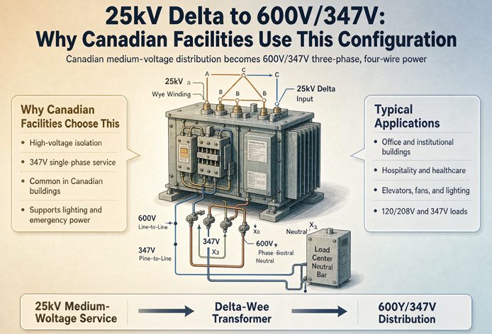
The secondary is a wye. Three coils meet at a star point, that star point is brought out as X0, and the result is two voltages from one winding. Line to line is 600 V. Line to neutral is 600 divided by the square root of three, which is 346.4, and the nominal is written 347.
This is the entire trick, and it is worth being explicit about what it buys. A single four wire secondary serves two different classes of load without a second transformer. The 600 V line-to-line feeds motors, chillers, air handling units, elevators, and anything with a three phase nameplate. The 347 V line-to-neutral feeds lighting. Not a 347 to 120 transformer in between, not a separate lighting panel fed from a separate transformer, just three phase conductors and a neutral doing both jobs.
Every commercial building in Canada is wired this way, and every Canadian electrician reads 347 V the way a US electrician reads 277 V. Same idea, one voltage class up.
Why the nameplate says Dyn1
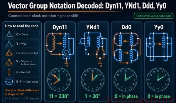
D is a delta primary. y is a wye secondary. n is a neutral brought out. 1 is the clock position, meaning the secondary line-to-neutral voltage lags the primary line-to-neutral voltage by 30 degrees.
The 30 degrees is not optional and it is not a preference. A delta winding’s line voltage is a coil voltage, and a wye winding’s line voltage is the vector difference of two coil voltages 120 degrees apart, so the act of going from delta to wye rotates the output by 30 degrees. The only question is which direction, and North American practice puts the low side lagging. IEC practice often puts it leading, which is clock 11 and is written Dyn11. Both are the same transformer with the leads brought out differently, and the difference matters the day someone tries to parallel two units from different suppliers. If you want the notation itself decoded, including why clock 10 does not exist, that is a separate subject. For this configuration, remember only that Dyn1 is what a Canadian utility expects to see, and a Dyn11 unit is not interchangeable in a paralleled lineup.
Why 600 V and not 480 V
The honest answer is not “because Canada.” Canada and the United States share a 60 Hz grid, share transformer factories, and share most equipment standards. The divergence is one rung on a ladder, and once you see the ladder the choice looks less like a national habit and more like the only option.
600 volts is the top rung of the low voltage ladder
Equipment standards define a low voltage world and a medium voltage world, and the border between them sits at 600 V. Dry type transformers are listed to UL 1561 up to 600 V and to UL 1562 above 601 V. Molded case circuit breakers are built in a 600 V class. Cable rated 600/1000 V is a commodity; cable above that is shielded medium voltage cable with semiconductive layers, stress control and a completely different installation trade.
Then there is the code itself. The Canadian Electrical Code puts installations above 750 V into Section 36, which brings its own requirements for clearances, guarding, and work by qualified high voltage personnel. A 600Y/347 V system has a maximum voltage to ground of 347 V, so nothing in the building distribution crosses that line. The 25 kV service does, and that is fine, because it stops at one piece of equipment. Everything downstream of the transformer terminals is ordinary low voltage work under the ordinary sections of the code.
Put those two facts together and the logic is clean. 600 V is the highest distribution voltage available in Canada that keeps the entire building inside the low voltage equipment world and inside the low voltage sections of the code. A design that went to 690 V would need medium voltage cable, medium voltage terminations and medium voltage people to serve the same loads. IEC countries use 690 V precisely because their low voltage ceiling is 1,000 V. Canada’s ceiling is 600 V, so 600 V is the top of the ladder, and there is nothing between it and the next world.
That is also why you will not find a 600 V to 690 V transformer in a Canadian plant. There is no equipment to feed.
The conductor arithmetic, 40 percent less copper
At 600 V, one kVA costs 0.9623 amps. At 480 V the same kVA costs 1.2028 amps. Divide one by the other and you get exactly 1.25, which is not a coincidence, it is 600 divided by 480.
So a 600 V system carries 80 percent of the current for the same load. The naive conclusion is 20 percent less copper. The real answer is better, because conductors come in discrete sizes and the 20 percent lands you two rungs down the ladder rather than one.
| Transformer | At 480 V, 125 percent of FLA | Conductor at 480 V | At 600 V, 125 percent of FLA | Conductor at 600 V | Copper saved |
|---|---|---|---|---|---|
| 1,000 kVA | 1,503.5 A | 3 sets of 1,000 kcmil, 3,000 kcmil | 1,202.8 A | 3 sets of 600 kcmil, 1,800 kcmil | 40 percent |
| 1,500 kVA | 2,255.3 A | 6 sets of 500 kcmil, 3,000 kcmil | 1,804.2 A | 6 sets of 350 kcmil, 2,100 kcmil | 30 percent |
| 2,000 kVA | 3,007.0 A | 6 sets of 1,000 kcmil, 6,000 kcmil | 2,405.6 A | 6 sets of 600 kcmil, 3,600 kcmil | 40 percent |
Hold the number of conduits constant, which is how the decision actually gets made, and the conductor size is what changes. On a 1,000 kVA unit that is 1,000 kcmil dropping to 600, with the same three raceways, the same three pulls, and the same labor. On a 2,000 kVA unit it is 6,000 kcmil of copper becoming 3,600.
The 1,500 kVA row is the odd one at 30 percent, and it is worth knowing why, because it is the row most likely to be designed. At 480 V the ampacity lands at 2,255 A, which is four sets of 700 or six sets of 500, and at 600 V it lands at 1,804 A, which is six sets of 350. The ratio of current is still 1.25, but the ladder does not cooperate at that particular rung, so the saving is smaller than at the sizes either side of it. If someone tells you 600 V always saves 40 percent on copper, they have only checked two rows.
There is a second, quieter saving. Parallel conductor sets need a minimum size of 1/0 AWG under Article 310 in the US and Rule 12-108 in Canada, so the number of sets is capped at the bottom by the smallest legal parallel conductor and at the top by 1,000 kcmil, the largest single conductor in common supply. At 600 V you sit further from that 1,000 kcmil ceiling, which is why a 2,000 kVA unit can be built with six moderate sets instead of six very large ones.
What it does to the switchboard
Here is where the higher voltage pays a dividend that surprises people, because the intuition runs the wrong way. Lower voltage means higher current, and higher current means higher fault current for the same transformer. So 600 V is gentler on the gear, not harsher.
Fault current at the secondary terminals is full load current divided by per unit impedance, which at 5.75 percent is 17.39 times full load current. Multiply that by the amps per kVA and you get the fault current per kVA of transformer.
| Gear class | Maximum kVA at 600 V, 5.75 percent | Maximum kVA at 480 V, 5.75 percent | Extra kVA at 600 V |
|---|---|---|---|
| 10 kA | 598 | 478 | 25 percent |
| 22 kA | 1,315 | 1,052 | 25 percent |
| 42 kA | 2,510 | 2,008 | 25 percent |
| 65 kA | 3,884 | 3,107 | 25 percent |
A 22 kA switchboard carries 1,315 kVA of transformer at 600 V, and 1,052 kVA at 480 V. That is 25 percent more transformer behind the same board, at every gear class, for the same reason as the conductor saving.
The practical version of that table is a margin question. A 1,000 kVA unit at 600 V produces 16,735 amps of fault current, which leaves 5,265 amps of headroom under a 22 kA board. The same 1,000 kVA unit at 480 V produces 20,918 amps, which leaves 1,082 amps. Motor contribution eats 1,082 amps without trying. A plant with a few hundred connected horsepower will push a 480 V board over 22 kA and force a 42 kA section, and the identical plant at 600 V will not.
That is the real reason a Canadian designer does not fight for 480 V. Not the transformer price, which is close. The switchboard class, which is not.
Why 347 V is the number that decides the building
Most explanations of this configuration spend their words on 600 V and treat 347 as a footnote. It is the other way round. 600 V decides the motors. 347 V decides how many panels, circuits and breakers the building needs, because lighting is the load that spreads across every square foot.
Lighting without a second transformer
At 347 V, a 20 amp lighting circuit at 80 percent loading carries 5,552 volt-amperes. At 277 V, the US equivalent, the same circuit carries 4,432. At 120 V it carries 1,920.
| Circuit | Usable VA at 80 percent | Circuits for 75 kW of lighting | Relative circuit count |
|---|---|---|---|
| 20 A at 347 V | 5,552 | 14 | 1.00 |
| 20 A at 277 V | 4,432 | 17 | 1.21 |
| 20 A at 120 V | 1,920 | 40 | 2.89 |
Fourteen circuits instead of seventeen is a modest saving. Fourteen instead of forty is the difference between one lighting panel and three, and between a 600 V to 120 V transformer and no transformer at all. That is the comparison that matters, because the second transformer is not just its purchase price, it is a room, a feeder, a breaker, a heat load, and a piece of equipment that has to be maintained for thirty years.
The equipment exists as a standard category rather than a special order, which is the part buyers worry about. UL 1993 covers self-ballasted lamps and lamp adapters from 120 to 347 V. CSA C22.2 No. 250.570 covers track lighting systems rated 347 V and 40 A. Lighting controls listed to UL 773A are rated to 347 V. A Canadian electrical wholesaler stocks 347 V luminaires the way a US wholesaler stocks 277 V ones.
The 120 V load you still have to serve
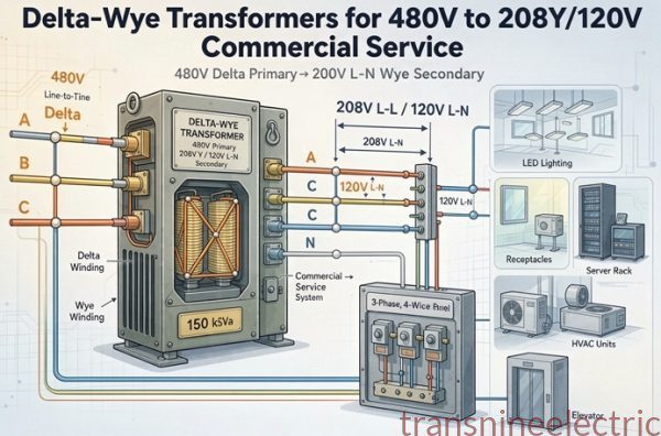
Every Canadian building still has a 600 to 208Y/120 V transformer in it, or a 600 to 120/240 V single phase unit for a small one. You cannot put a convenience receptacle on 347 V, and you cannot put a computer room on it either. The 347 V winding feeds lighting and fixed equipment, and that is the end of its usefulness.
The usual split puts 5 to 15 percent of the building load on that second transformer: receptacles, office equipment, the IT closet, fire alarm, security, anything with a cord cap.
| Second transformer | Primary amps at 600 V | Secondary amps at 208 V | Typical load served |
|---|---|---|---|
| 75 kVA | 72.2 | 208.2 | One floor of receptacles in a small building |
| 112.5 kVA | 108.3 | 312.3 | Office area, 30 to 40 workstations |
| 150 kVA | 144.3 | 416.4 | Office plus a small server room |
| 225 kVA | 216.5 | 624.5 | Full office floor with kitchen loads |
| 300 kVA | 288.7 | 832.7 | Office tower floor, or a data closet with growth |
So the accurate description of the architecture is two transformers and three usable voltages, not one transformer that does everything. The 25 kV to 600Y/347 V unit is the main. The 600 to 208Y/120 V unit is the one that makes the building usable by people rather than by machines. A designer who forgets the second one has a building where the lights work and nothing can be plugged in.
Where 347 V stops
Three limits are worth knowing before the panel schedules are drawn.
The first is that 347 V is a lighting and fixed equipment voltage, not a motor voltage. Motors on a 600 V system are nameplated 575 V, not 600, and the ratio is the same one US designers already know: 460 divided by 480 is 0.958, and 575 divided by 600 is 0.958. The utilization voltage convention is identical in both countries. Only the system voltage moved.
The second is that a 347 V circuit is a line-to-neutral circuit fed from a solidly grounded wye, so a line-to-ground fault on it is a real fault with real current, cleared by the branch breaker. That is an advantage over an ungrounded system, and it is the reason the 600 V side is grounded even though the 25 kV side is not. The two sides of the same transformer have completely different grounding philosophies, and that is normal.
The third is the neutral itself. In a building with a lot of electronic lighting drivers, the third harmonic current on the neutral adds arithmetically across the three phases, so a neutral sized at 100 percent of the phase conductor can be fully loaded while the phases are not. A 200 percent neutral is cheap insurance on a lighting-heavy panel, and it costs almost nothing at the ordering stage.
Why the primary is delta
Now the other end. The utility side of this transformer is a delta, and the reasons are mostly the utility’s, not yours.
Three wires instead of four
A 25 kV delta feeder is three conductors. No neutral, no fourth wire, no neutral grounding at every transformer along the way. On a long rural or industrial feeder that is real money per mile, and it is the reason Canadian distribution practice leaned this way in the first place.
There is an operational reason too. On an ungrounded delta, a single line-to-ground fault does not interrupt service. The lights stay on, the plant keeps running, and a detection system tells somebody to go find the fault. For a sawmill, a mine, or a paper machine, that continuity is worth more than the cost of the wire.
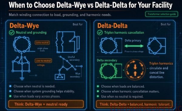
The consequence at your transformer is that there is no primary neutral to connect to. The delta winding is a closed loop with no external star point, so the transformer cannot return zero sequence current to the utility even if it wanted to. That is a feature from the utility’s point of view, because a customer’s unbalanced secondary load does not show up as zero sequence on their feeder. It is also why the secondary neutral is stable, because the primary delta circulates the zero sequence current internally and cancels the ampere turns. The mechanism is worth understanding in its own right, but for this configuration the takeaway is simpler: the missing primary neutral is what makes the secondary neutral behave.
The dual voltage winding
Look closely at a Canadian nameplate and you will often see 24940/12470 instead of a single high side voltage. Those are two half windings per phase, six coils in a delta, brought out so they can be connected in series for the 25 kV class or in parallel for the 12.47 kV class.
The commercial value is inventory. One spare unit covers two system voltages, and a used unit with that nameplate can move between provinces and between utilities without being rewound. It is common enough that a 2,000 kVA, 24940/12470 delta, 600Y/347 V dry type unit sitting on a resale lot is not an unusual sight. That is a signature of the configuration, not a sign that something went wrong.
Two things to check when you use one. Reconnecting from series to parallel doubles the primary current, so the primary fuse and the conductor ampacity have to be re-evaluated, and the tap settings start over. And the impedance in the parallel connection is roughly a quarter of the series value, because impedance scales with the square of turns, so the fault current at the secondary quadruples for the same kVA. That last point catches people who move a unit from a 25 kV site to a 12.47 kV site and reuse the old coordination study.
Where delta stops being free
A delta primary cannot do three things, and each one shows up as a project constraint.
It cannot serve a single phase load from the primary. There is no neutral, so a 25 kV to 14.4 kV single phase tap is not available from the same winding. If the site needs single phase high side power for a small transformer, it comes from a separate single phase unit connected phase to phase, or not at all.
It cannot be the grounding source for the 25 kV system. If the utility wants a grounded 25 kV system they will supply 25GrdY/14.4 instead of 25 kV delta, and then the primary is a wye and the whole ungrounded discussion in the next section disappears. Both configurations exist in Canada, sometimes on the same street, and the nameplate tells you which one you have. A unit ordered for a grounded wye primary and installed on a delta system, or the reverse, has a winding connected for the wrong voltage class, and it will not survive energization.
It cannot be paralleled with a wye primary unit. Different vector group, different zero sequence behavior, and in most cases a different clock number.
The practical instruction is one line on the RFQ: state the primary connection as the utility described it, and attach the utility’s service letter. Not “25 kV.” Not “25 kV class.” The connection, the nominal voltage, and whether the source is grounded.
What the delta costs you on the primary
The ungrounded primary is the part of this configuration that a US buyer is least prepared for, because almost nothing in US commercial practice is ungrounded above 600 V. Four costs follow from it, and they are all predictable once you know to look.
An ungrounded system has to be watched
Canada permits ungrounded systems, and the code is specific about what comes with the permission. Rules 10-400 and 10-402 of the Canadian Electrical Code set the conditions: ground fault detection, maintenance by qualified persons, and a continuous, clearly labelled visual or audible alarm when a ground fault occurs. The alarm is not optional and it is not a nice-to-have. It is the substitute for the fault current that a grounded system would have used to trip something.
The physics explains why the alarm is the whole safety case. On a 25 kV delta there is no deliberate connection to earth, so a single line-to-ground fault has no metallic return path. The only current that flows is the capacitive charging current of the system’s own cables. For 25 kV cable, a working figure is around 60 nanofarads per mile per phase, which at 14.4 kV to ground gives about 0.33 amps per mile per phase, or roughly 1 amp per mile for a three phase run. A three mile loop with a single ground fault draws around 3 amps.
Three amps will not trip a 25 kV feeder. It will not even show up on a clamp meter held around a three conductor cable, because the three phase currents cancel and the residual is small. It will heat nothing and trip nothing, and the plant will run for months with a phase intermittently arcing to ground. That is the deal the utility made: continuity in exchange for a fault that has to be hunted with a pulsing detector.
There is a second half to that deal, and it is the one that hurts. With one phase already grounded, a second ground fault on a different phase is a phase-to-phase fault through earth. That fault has a full metallic path, it draws the transformer’s full through-fault current, and it is violent. The window between the first fault and the second is the entire value of the detection system.
The 24.94 kV that appears on the healthy phases
During a single line-to-ground fault on an ungrounded system, the two healthy phases rise to the full line-to-line voltage above ground. Not a little above nominal. The full 24,940 volts, which is 1.73 times the normal 14.4 kV line-to-ground stress.
Everything on the primary side is selected for that number rather than for the normal one. The cable insulation, the transformer’s high side BIL, the surge arrester rating, the clearance distances, all of it. This is the single most consequential fact about an ungrounded delta, and it is the reason a 25 kV delta service is not simply a 25 kV grounded service with one wire removed.
For the arresters it means the rating has to cover line-to-line voltage continuously, not line-to-neutral, which moves the arrester two or three steps up the standard rating ladder compared to what a grounded 25 kV system would use. For the transformer it means the high side BIL is set by the insulation coordination study, not by the nominal voltage, and 125 kV at the 25 kV distribution class is the floor rather than the answer if the site is exposed or the utility specifies more.
Cable insulation, 260 mils or 345
Medium voltage cable is sold in insulation levels, expressed as a percentage of the rated voltage to ground. The percentage is a statement about how long a ground fault is allowed to persist, not about the normal operating voltage.
| Insulation level | 25 kV cable wall | Ground fault duration assumed | Use on this configuration |
|---|---|---|---|
| 100 percent | 260 mils | Cleared in about a minute | Only if the source is grounded and the protection is fast |
| 133 percent | 345 mils | Up to about an hour | The default for an ungrounded delta |
| 173 percent | 345 mils at the next voltage class | Longer than an hour | Rare, and usually handled by buying 35 kV cable |
On an ungrounded 25 kV delta you buy 133 percent, which is 345 mils. The fault can persist indefinitely by design, so the 100 percent cable that assumes a one minute clearing time is the wrong product even though the voltage rating on the label looks the same.
The cost is not just the insulation. A thicker wall grows the outside diameter of the whole assembly, and conduit fill goes with the square of that diameter.
| Conductor | Cable OD at 260 mil | Cable OD at 345 mil | Cross section increase |
|---|---|---|---|
| 2 AWG | 0.812 in | 0.982 in | 46 percent |
| 1/0 AWG | 0.895 in | 1.065 in | 42 percent |
Forty odd percent more cross section on the same conductor is the difference between three cables in a 4 inch conduit and three cables that need a 5 inch, and it changes reel lengths, pull tensions and the size of every handhole. It also changes the price per foot by more than the insulation thickness ratio, because the semiconductive layers and the jacket grow with the diameter too.
One small mercy. A 25 kV cable at 133 percent and a 35 kV cable at 100 percent are the same 345 mil wall. Utilities know this, manufacturers build both on the same line, and the price difference between them is smaller than the numbers on the labels suggest. If a supplier quotes 35 kV cable for a 25 kV job because it is what they stock, the electrical result is acceptable and the only question is termination hardware.
The zig-zag option
A plant that wants the continuity of an ungrounded system but not the hunting can add a grounding transformer on the 25 kV bus. A zig-zag unit creates a neutral point that does not exist in the delta, and a resistor between that neutral and ground turns the system into a resistance grounded one.
What that buys is a defined fault current. Instead of 3 amps of charging current that nothing can measure reliably, a ground fault draws a known current set by the resistor, a relay sees it, and the response is a decision rather than a surprise. The resistor is usually sized so the fault current is a small multiple of the system charging current, which keeps the fault detectable without making it destructive.
What it costs is a transformer, a resistor, a relay, and the space for all three, plus a change to the grounding philosophy that has to be reflected in the single line and in the operating procedures. On a plant with a handful of 25 kV transformers and a maintenance department that will actually respond to an alarm, it is often the right call. On a single 1,000 kVA unit serving a warehouse, plain detection with an alarm is usually enough.
The protection arithmetic almost nobody does
This is the section that separates a Canadian submittal from a translated US one, because the rule that governs a 25 kV transformer is not the rule most articles quote.
CEC 26-250 is not CEC 26-254
Two rules in Section 26 look similar and apply to completely different equipment.
Rule 26-254 covers dry type transformer circuits rated 750 V or less. It sets primary overcurrent protection at not more than 125 percent of rated primary current, allows the next higher standard rating where 125 percent does not land on one, and permits the primary device to be omitted when the secondary device is set at not more than 125 percent of rated secondary current and the primary feeder device is at not more than 300 percent.
Rule 26-250 covers power and distribution transformer circuits rated over 750 V. It sets the primary device at not more than 150 percent of rated primary current for fuses, and not more than 300 percent for breakers. Subrule 4 allows the individual primary device to be omitted where the secondary device is within the values of Table 50 or the unit has manufacturer coordinated thermal overload protection, provided the primary feeder device is also within Table 50.
A 25 kV to 600Y/347 V transformer is over 750 V on its primary. Rule 26-250 applies. Rule 26-254, the 125 percent rule that every Canadian guide quotes, does not.
That is a 25 percentage point difference in the fuse size, and it is the difference between a unit that energizes cleanly and one that trips the primary fuse every time the utility recloses. It also explains a recurring argument in Canadian plants, where an electrician trained on 600 V dry types applies 125 percent to a 25 kV unit, the fuse nuisance trips, and the fix is to move up to the 150 percent the rule always allowed.
A 46 amp primary
Take a 2,000 kVA unit at 24,940 V. Full load current is 46.30 amps.
Fifteen percent headroom on that is 69.45 amps. The next standard E rated fuse above it is 80 amps.
An 80 amp fuse protecting two megawatts of transformer is the 25 kV side in one line. It is smaller than the service fuse on a suburban house, and it is the reason the primary compartment of one of these units is a small box with three cables and a fuse holder rather than a switchgear lineup.
The breaker version has more room. Three hundred percent of 46.30 is 138.9 amps, so a 125 amp breaker frame fits, and a 150 amp frame fits if the long time setting is dialed down below 138.9. What you cannot do is install the breaker and leave it at its frame rating, because the rule is about the setting, not the label.
| kVA | Primary amps at 24,940 V | 150 percent, fuse maximum | 300 percent, breaker maximum |
|---|---|---|---|
| 500 | 11.57 | 17.36 | 34.72 |
| 750 | 17.36 | 26.04 | 52.09 |
| 1,000 | 23.15 | 34.72 | 69.45 |
| 1,500 | 34.72 | 52.09 | 104.17 |
| 2,000 | 46.30 | 69.45 | 138.90 |
| 2,500 | 57.87 | 86.81 | 173.62 |
| 3,000 | 69.45 | 104.17 | 208.35 |
Read that table as a set of ceilings rather than recommendations. The fuse column is a maximum that the code permits, and the next standard fuse rating above it is what actually goes in the holder. The breaker column is a maximum setting, and a breaker set above it is a code violation even if the frame is correctly sized.
The 45 percent window between inrush and fault
Here is the piece of arithmetic that decides the impedance on the purchase order, and it takes two numbers.
The first is inrush. The Appendix B note that accompanies the transformer protection rules expects the primary device to carry 12 times rated current for 0.1 second, and 25 times for 0.01 second, without operating. That is the energization pulse, and it is not a fault, so the device has to sit through it.
The second is the through-fault current. A transformer’s fault current is its full load current divided by its per unit impedance, so at 5.75 percent the primary sees 17.39 times full load current when there is a bolted fault on the secondary.
The ratio between those two numbers is the entire protection design. At 5.75 percent it is 1.45, which is a 45 percent window. At 7.5 percent it is 1.11, which is an 11 percent window. At 8 percent it is 1.04, which means the fuse cannot reliably tell a fault from an energization, and the design has no margin at all.
| Impedance | Through fault, times FLA | Ratio to the 12 times inrush assumption | Available window |
|---|---|---|---|
| 4.5 percent | 22.22 | 1.85 | 85 percent |
| 5.0 percent | 20.00 | 1.67 | 67 percent |
| 5.75 percent | 17.39 | 1.45 | 45 percent |
| 6.5 percent | 15.38 | 1.28 | 28 percent |
| 7.0 percent | 14.29 | 1.19 | 19 percent |
| 7.5 percent | 13.33 | 1.11 | 11 percent |
| 8.0 percent | 12.50 | 1.04 | 4 percent |
On the 2,000 kVA unit with an 80 amp fuse, the numbers become concrete. Inrush is 12 times 46.30, which is 555.6 amps, or 6.95 times the fuse rating, and the fuse must hold that for a tenth of a second. A bolted secondary fault puts 805 amps through the primary, which is 10.06 times the fuse rating, and the fuse must clear that. A fuse that holds 6.95 times and clears 10.06 times is doing real work, and it only has a 45 percent gap to work in.
This is the argument for ordering 5.75 percent impedance rather than the 7.5 percent that a US dry type catalogue might default to. It is not about fault current, where lower impedance is worse. It is about whether the primary device can distinguish the two events at all. Lower impedance widens the window, at the cost of a higher fault current on the 600 V side and a larger gear class. That trade is the real impedance decision, and it has three corners rather than two.
Why the trade has three corners
The three corners are the fuse window, the 600 V gear class, and voltage regulation.
Lower impedance widens the fuse window and raises the fault current, so it buys protection margin and costs gear. Higher impedance narrows the window and lowers the fault current, so it saves gear and risks nuisance tripping on energization. And impedance also shows up as voltage drop under load, because the series impedance that limits fault current is the same impedance that drops volts when current flows, so a high impedance unit sags more at full load on a feeder that is already at the bottom of its voltage band.
| Impedance | Fuse window | Fault current, 2,000 kVA at 600 V | Gear class needed | Regulation at full load |
|---|---|---|---|---|
| 4.5 percent | 85 percent | 42,767 A | 65 kA | Best |
| 5.75 percent | 45 percent | 33,470 A | 42 kA | Good |
| 7.5 percent | 11 percent | 25,661 A | 42 kA | Poorer |
The middle row is why 5.75 percent is the number on most Canadian units at this size. It gives the fuse a workable window, it keeps the fault current inside a 42 kA board, and it keeps regulation acceptable. Below 5.75 you pay for gear you do not need. Above it you start buying a fuse problem.
Sizing the 600 V side
The secondary side is where the arithmetic is familiar to anyone who has sized a US service, with one number changed and one rule that is Canadian.
Conductors at 125 percent
Rule 26-256 requires the conductors supplying a transformer to have an ampacity of not less than 125 percent of the rated primary current, and the secondary conductors to have an ampacity of not less than 125 percent of the rated secondary current. That is the same 1.25 factor the National Electrical Code uses, and it applies to the conductor rather than to the device.
On a 1,500 kVA unit, secondary current is 1,443.4 amps, so the conductor has to carry 1,804.2 amps. Six sets of 350 kcmil copper at 75 degrees gives 1,860 amps, which clears it with 56 amps to spare, and uses 2,100 kcmil of copper per phase. Four sets of 700 kcmil also clears it at 1,840 amps with 2,800 kcmil, which is fewer conduits and 33 percent more copper.
| Option for 1,804 A | Sets | Ampacity | Total copper | Conduits |
|---|---|---|---|---|
| 350 kcmil | 6 | 1,860 A | 2,100 kcmil | 6 |
| 500 kcmil | 5 | 1,900 A | 2,500 kcmil | 5 |
| 700 kcmil | 4 | 1,840 A | 2,800 kcmil | 4 |
| 1,000 kcmil | 4 | 2,180 A | 4,000 kcmil | 4 |
Which row is right depends on labor, not on copper. Four pulls of 700 in four conduits is less labor than six pulls of 350 in six, and on a short run inside a switchgear room the labor difference usually wins. On a long underground run, the copper wins. The point is that the table has four legitimate answers and the choice is a cost question, which is not something the code decides for you.
The device ladder
The secondary device is sized at 125 percent of rated secondary current and rounded up to a standard rating. On the 1,500 kVA unit, 125 percent is 1,804.2 amps, so the device is 2,000 amps. That is 138.6 percent of full load current, which sounds generous until you notice the transformer is then loaded to 72 percent at its rating, which is exactly where a distribution transformer wants to sit.
The same overshoot appears at every size, because the standard rating ladder is coarse relative to the gaps between transformer sizes. A 2,000 kVA unit at 600 V needs 2,405.6 amps and gets a 2,500 amp device, which is 129.9 percent. A 1,000 kVA unit needs 1,202.8 and gets a 1,250 amp device, which is 129.9 percent as well. The overshoot is not a design choice, it is the ladder.
The 22 kA line at 1,315 kVA
A 1,500 kVA unit at 600 V produces 25,102 amps of fault current at 5.75 percent, which is over the 22 kA class and into 42 kA. The line sits at 1,315 kVA.
That is the cliff in this configuration, and it lands right between two standard sizes. A 1,000 kVA unit sits at 16,735 amps, comfortably inside 22 kA. A 1,500 kVA unit sits at 25,102, which is 14 percent over. There is no 25 kA gear class to absorb that, so the next step is 42 kA and the switchboard price moves accordingly.
The practical consequence is that the 1,000 to 1,500 kVA step is the most expensive size increase in the Canadian ladder, because it crosses a gear class as well as a transformer size. A project that could live with 1,200 kVA of capacity and does not have a 1,200 kVA standard size in front of it will often take the 1,000 kVA unit and a second one later rather than the 1,500 and the 42 kA board.
One Canadian rule makes that decision harder, and it is worth knowing before you try to buy headroom. Rule 26-258 ties the continuous load on the transformer secondary to the rating of the circuit, by reference to Rule 8-104. In plain terms, the calculated continuous load cannot exceed the rating of the circuit the transformer sits in, which is set by the device and the conductor. Buying a bigger transformer does not create load headroom unless the device and the conductors are sized for it too. On this side of the border, the transformer is part of a circuit rather than a standalone reservoir of capacity.
The voltage band is not symmetric
US designers arrive with ANSI C84.1 Range A in their heads, which is plus or minus 5 percent at the service. Canada’s standard is a different shape, and the difference is not academic on a 600 V system.
550 to 625
CSA CAN3-C235-19, Preferred Voltage Levels for AC Systems from 0 to 50,000 V, sets the 347/600 V wye band as follows. Normal operating range is 318 to 360 volts line to neutral, and 550 to 625 volts line to line. Extreme operating range is 306 to 367 and 530 to 635.
| Nominal | Normal minimum | Normal maximum | Deviation | Extreme minimum | Extreme maximum |
|---|---|---|---|---|---|
| 600 V line to line | 550 V | 625 V | minus 8.33 to plus 4.17 percent | 530 V | 635 V |
| 347 V line to neutral | 318 V | 360 V | minus 8.36 to plus 3.75 percent | 306 V | 367 V |
Read the deviation column. It is not plus or minus 5. It is minus 8.33 and plus 4.17, which is a band that allows twice as much sag as it allows rise. That is deliberate. The standard assumes the voltage will fall as it moves through the customer’s own distribution, so it gives the utility room at the bottom and holds a tighter lid at the top.
The consequence is that 550 volts at the service entrance is a legal, normal, everyday condition on a Canadian 600 V system. Not a fault, not an emergency, not something the utility has to fix. A plant at the end of a long rural 25 kV feeder can sit there for years.
84 percent torque at the bottom
Torque in an induction motor varies with the square of the applied voltage. At 550 volts, a 575 V motor sees 95.7 percent of its nameplate voltage, and the torque available is 0.957 squared, which is 91.5 percent. Relative to the 600 V system nominal, the number is 550 over 600 squared, which is 0.840.
Either way of counting, the answer is that the bottom of the normal band costs a motor somewhere between 8 and 16 percent of its torque, depending on which voltage you call nominal. At 625 volts the same motor has 108.5 percent of nominal torque and starts to saturate, which wastes a little energy and heats the core a little, but does not damage anything.
This is why Canadian 600 V designs specify 575 V motors with a 1.15 service factor and why nobody picks a motor sized exactly at its load. The band does the derating for you, whether you planned for it or not.
What taps can and cannot fix
A distribution transformer of this size comes with a de-energized tap changer, usually plus or minus 2 by 2.5 percent, which is plus or minus 5 percent in four steps. The taps are on the primary, so a 5 percent buck tap reduces the primary turns by 5 percent and raises the secondary voltage by 1 divided by 0.95, which is 5.26 percent.
The band allows the service to sit 9.09 percent low, which is the boost needed to bring 550 volts back to 600. The standard tap range covers 5.26 of that 9.09, which is 58 percent of the worst case.
So taps handle the ordinary drift and do not handle the bottom of the band. If the utility’s service letter says the site runs at the low end, or if the plant is at the end of a long feeder, specify a wider tap range. Plus or minus 4 by 2.5 percent gives plus or minus 10 percent, which covers the whole band with room to spare.
One ordering trap on the way. CSA C802.1 excludes transformers with a tap range greater than 20 percent from its efficiency table. A plus or minus 4 by 2.5 percent range is 20 percent total and stays inside. A plus or minus 5 by 2.5 percent range is 25 percent total and takes the unit out of the table you were counting on for compliance. If you need a very wide tap range, that conversation has to happen before the efficiency claim is made, not after.
Efficiency: which table Canada actually enforces
A US buyer assumes the federal table applies, because in the US it does. In Canada there are two tables and they have different legal standing, which changes what goes in a submittal.
C802.1 is voluntary, C802.2 is not
Liquid filled distribution transformers in Canada are covered by CSA C802.1, Minimum efficiency values for liquid-filled distribution transformers. The current edition is C802.1:23, the third, and it supersedes the 2013 and 2000 editions. Its scope is single phase units from 10 to 833 kVA and three phase units from 15 to 3,000 kVA, insulation class 34.5 kV and less, with a low voltage winding of 600 V or less.
The legal status is the part that surprises people. In Canada the liquid filled table has historically been applied through a voluntary agreement between Natural Resources Canada and the Canadian Electricity Association rather than as a regulated minimum, and provincial utilities write it into their procurement specifications instead. The practical effect is that almost every utility bought unit meets it, because the utility is the buyer. The formal effect is that a private developer buying a liquid unit for a industrial site is not staring at the same legal requirement a US buyer faces under 10 CFR 431.
Dry type transformers are the opposite. CSA C802.2 sets the values, and they are made mandatory through the Energy Efficiency Regulations administered by NRCan, covering single phase units from 15 to 833 kVA and three phase units from 15 to 7,500 kVA, with a primary of 35 kV or less and a secondary of 600 V or less. That table has force.
So the compliance question on a 25 kV to 600Y/347 V unit is not “what kVA is it.” It is “liquid or dry.” Get that backwards and the submittal cites a table that does not bind the product.
One piece of good news. The 2023 edition of C802.1 recalculated its individual values so that they reflect the minimum averages required by 10 CFR 431, and its preface says so. The two tables have converged on the numbers even though they have not converged on the legal mechanism. A unit built to the US table is now very close to the Canadian one, and the remaining difference is in how compliance is proven rather than in the watts.
Where 600 V sits in the scope
The scope boundary is a low voltage winding of 600 V or less, and a 600Y/347 V secondary sits exactly on it. Not above it, not below it. A 600 V unit is in scope.
Three exclusions are worth knowing because this configuration can trip them.
The first is a low voltage winding with a nominal line current of 4,000 amps or more at base kVA. At 600 V that is 4,157 kVA, and at 480 V it is 3,326 kVA. So the higher voltage pushes the exclusion up by 831 kVA of headroom, which means a 4,000 kVA unit at 600 V stays inside the table while the same unit at 480 V would not.
The second is a tap range greater than 20 percent, which is the trap described earlier. A wide tap range can take a unit out of the efficiency table.
The third is special impedance. If the utility asks for something outside the normal range for fault current reasons, the unit may no longer be a standard product for efficiency purposes, and the conversation with the supplier changes.
Read the table at 50 percent, not at full load
Both the Canadian and the US tables publish efficiency at 50 percent of rated capacity. That is not where the transformer runs, it is where the standard decided to measure, and the choice reflects the fact that distribution transformers spend most of their lives at part load.
The practical consequence is that a unit sitting at 99.0 percent at 50 percent load will not be at 99.0 percent at full load. It will be lower, because load loss rises with the square of the current while core loss stays flat. So a compliance claim is a claim about one operating point, and a design that meets the table at 50 percent can be a percent worse at 100. That is normal and permitted. It is also why the loss evaluation in a utility tender uses a capitalized loss formula rather than the table value, because the table tells you whether you may sell the unit and the loss formula tells you what it costs to own.
A worked example, 1,500 kVA
Here is the whole design in one table, with every number traceable to a division. The load is a 1,500 kVA mixed industrial building: 600 V motors and HVAC, 347 V lighting, and a 225 kVA second transformer for the 120 V loads.
| Item | Value | Where it comes from |
|---|---|---|
| Transformer | 1,500 kVA, 24,940 V delta to 600Y/347 V, Dyn1 | Load calculation and utility service letter |
| Primary full load current | 34.72 A | 1,500,000 divided by 1.732 times 24,940 |
| Primary protection ceiling, fuse | 52.09 A | 150 percent per CEC 26-250 |
| Fuse selected | 60 A E rated | Next standard rating above 52.09 |
| Through fault on primary | 603.9 A | 34.72 divided by 0.0575 |
| Inrush on primary | 416.6 A for 0.1 s | 12 times 34.72 |
| Fuse sees inrush at | 6.94 times its rating | 416.6 divided by 60 |
| Fuse sees fault at | 10.06 times its rating | 603.9 divided by 60 |
| Secondary full load current | 1,443.4 A | 1,500,000 divided by 1.732 times 600 |
| Conductor ampacity required | 1,804.2 A | 125 percent per CEC 26-256 |
| Conductors selected | 6 sets of 350 kcmil, 1,860 A | 2,100 kcmil of copper per phase |
| Secondary device | 2,000 A | Next standard rating above 1,804.2 |
| Device as a percent of full load | 138.6 percent | 2,000 divided by 1,443.4 |
| Fault current at 600 V | 25,102 A | 1,443.4 divided by 0.0575 |
| Gear class required | 42 kA | 25,102 exceeds the 22 kA class |
| Second transformer | 225 kVA, 600 to 208Y/120 V | 216.5 A primary, 624.5 A secondary |
| Line to neutral voltage | 347 V | 600 divided by 1.732 |
Now the six decisions in order, because the order is the part that gets skipped.
Start with the load, not the transformer. Calculate the demand, apply 125 percent for the continuous portion, and convert to kVA at 600 V. A 1,100 kW demand at 0.92 power factor is 1,196 kVA, which with the continuous adder lands near 1,400, and the standard size above that is 1,500.
Check the gear class next, before anything else is priced. 1,500 kVA at 5.75 percent is 25,102 amps, which is over 22 kA. If the project cannot absorb a 42 kA board, the answer is a 1,000 kVA unit now and a second one later, and finding that out after the switchboard is released is expensive.
Then set the primary protection. 150 percent of 34.72 is 52.09, and the fuse is 60 amps. Check the inrush and fault multiples against the fuse curve you actually intend to buy, because 6.94 and 10.06 are the two numbers that decide whether the fuse works.
Then the secondary conductors and device. 1,804.2 amps of required ampacity, 2,000 amp device, and a conductor set that clears both. Six sets of 350 is the lean choice on copper and four sets of 700 is the lean choice on labor.
Then the voltage. Take the utility’s service letter, find the expected primary voltage, and decide whether the standard plus or minus 5 percent tap range covers it. At 550 volts secondary the answer is no, and the tap range becomes a specification item rather than a default.
Then the code path. Primary over 750 V, so Rule 26-250 governs protection and Section 36 governs the installation. Secondary at 600Y/347, so the ordinary low voltage rules govern everything downstream. Two different worlds meeting at one set of terminals, and the drawings should show the boundary clearly.
The voltage drop nobody budgets for
One number that does not appear on any nameplate but decides whether the building works. A transformer’s regulation at full load depends on the resistance and reactance split inside its impedance, not just on the impedance magnitude. For a 5.75 percent unit at this size, a representative split is 1.2 percent resistance and 5.62 percent reactance.
At full load and 0.9 power factor, that gives a regulation of about 3.6 percent. Put that on top of a service sitting at the normal minimum of 550 volts and the secondary arrives at 530 volts at full load, which is the extreme minimum of CAN3-C235-19 to within a volt.
So the bottom of the normal band plus full load equals the absolute floor of the standard. A building in that position has no margin left, and the first thing that complains will be a motor starter or a chiller control board, not the lighting. The fixes are a lower impedance unit, a wider tap range set to boost, or a service upgrade conversation with the utility. All three are cheaper before the transformer is ordered.
Five things that go wrong on these projects
These are the failure modes that show up repeatedly, in roughly the order they cost money.
Ordering 480Y/277 out of habit. A specification template copied from a US project produces a 480Y/277 V unit, and then the 575 V motors do not exist in the catalogue, the 347 V luminaires are the wrong voltage, and the whole distribution design has to be redone. The primary can be identical and the secondary is not interchangeable.
Forgetting the 120 V transformer. The 347 V winding feeds lighting and nothing with a cord cap. A building with no 600 to 208Y/120 V unit has working lights and no receptacles, no IT closet, and no fire alarm panel supply. The second transformer is 5 to 15 percent of the load and 100 percent of the usability.
Applying the 125 percent rule to a 25 kV primary. Rule 26-254 is for dry types at 750 V or less. A 25 kV unit falls under Rule 26-250, where the fuse allowance is 150 percent. Sizing at 125 percent produces a fuse that nuisance trips on energization, and the usual field fix is to keep replacing fuses rather than to read the rule.
Buying 260 mil cable for an ungrounded delta. The 100 percent insulation level assumes a ground fault is cleared in about a minute. On an ungrounded system it is not cleared at all, so the cable has to be 133 percent, which is 345 mils. The voltage rating on the label looks identical, which is why the mistake gets made.
Wiring the ground fault relay to trip. On an ungrounded 25 kV system the code wants detection and a labelled alarm, and the operational intent is continuity. A relay wired to trip the main turns every transient into an outage, and the first response is to disable the relay, which removes the only protection the system has.
What to put on the RFQ
Most of the bad outcomes above are specification failures, so the fix is a purchase order that says what you actually need. These are the fields that matter on this configuration, in the order a factory reads them.
| Field | What to write | Why it matters here |
|---|---|---|
| Primary voltage and connection | 24,940 V, 3 phase, 3 wire, delta, ungrounded | Confirms the class and the grounding philosophy |
| Primary source grounding | Utility 25 kV delta, ungrounded, or state 25GrdY/14.4 | Changes the winding, the BIL and the arrester |
| BIL | 125 kV minimum, or per the utility specification | Set by the insulation coordination study |
| kVA and basis | 1,500 kVA, demand plus 125 percent continuous | The only field the load calculation owns |
| Secondary | 600Y/347 V, 4 wire, X0 brought out and fully rated | The 347 V lighting depends on it |
| Neutral rating | 100 percent, or 200 percent for a lighting heavy panel | Third harmonic current adds on the neutral |
| Vector group | Dyn1 | Decides what it can parallel with |
| Impedance | 5.75 percent, with the tolerance stated as a number | Sets the fuse window and the gear class |
| Tap range | Plus or minus 2 by 2.5 percent, or wider for a low site | Covers 5.26 percent of a 9.09 percent band |
| Cooling and rise | ONAN, 65 degree rise, or AN for dry type | Sets the loading and the life |
| Efficiency basis | CSA C802.1 for liquid, CSA C802.2 for dry | Two different tables with different force |
| Enclosure | Pad mounted dead front, loop feed, per CSA C227.4 | The Canadian distribution standard for this product |
| Primary protection | Bay-O-Net with ELSP backup, or state the breaker | The 150 percent allowance depends on the device type |
| Ground fault detection | Alarm, not trip, on the ungrounded primary | Rules 10-400 and 10-402 expect an alarm |
| Marking | CSA label, and the connection diagram before shipment | The label is what the inspector looks for |
Two lines deserve their own sentence. The primary source grounding line is the one that most often goes missing, and it is the one that decides whether the whole ungrounded discussion applies at all. And the impedance tolerance deserves a number rather than a nominal, because a unit arriving at 5.2 percent instead of 5.75 changes the fault current and the fuse window at the same time.
The bottom line
This configuration is not a Canadian quirk. It is what you get when you take the highest voltage that still counts as low voltage, put a neutral on it, and feed it from a utility that saves a wire by running delta.
The three decisions that follow from it are all arithmetic rather than taste. 600 V instead of 480 saves 30 to 40 percent of the secondary copper and 25 percent of the gear class for the same kVA. 347 V instead of 277 gives 25 percent more lighting load per circuit and removes a transformer from the building. A 25 kV delta primary costs you an ungrounded system, which costs you 345 mil cable, an alarm you have to maintain, and a primary fuse that has to work inside a 45 percent window.
If you are holding a service letter and a load calculation for a Canadian building and want a second read on the kVA, the impedance, or whether the primary is really delta, start here and send the utility letter, the single line, and the demand calculation. The useful answer needs those three, and it takes about a day.
FAQ
What is 600Y/347 V?
A four wire three phase system with 600 volts line to line and 347 volts line to neutral. The 347 comes from 600 divided by the square root of three, which is 346.4 and is written 347 as a nominal value. It is the standard commercial and industrial distribution voltage in Canada, the way 480Y/277 V is in the United States.
Why does Canada use 600 V instead of 480 V?
Because 600 V is the highest voltage that stays inside the low voltage equipment world. Dry type transformers are listed to 600 V under UL 1561, breakers come in a 600 V class, and the Canadian Electrical Code moves installations above 750 V into Section 36. A 600Y/347 V system has a maximum of 347 V to ground, so the whole building stays low voltage while 25 kV does not.
Is 347 V the same as 277 V?
No. They are the same idea at different voltages. 277 is 480 divided by 1.732, and 347 is 600 divided by 1.732. A 347 V luminaire cannot be fed from a 277 V system, and a 277 V luminaire on a 347 V circuit will fail. The equipment standards cover both, but the products are different catalogue items.
Why is the primary delta and not wye?
Because the utility is supplying three wires rather than four. A delta feeder has no neutral conductor and no neutral grounding at each transformer, which is cheaper per mile, and a single line-to-ground fault does not interrupt service. The customer side consequence is that the transformer has no primary neutral to connect to, which is why the primary protection and the grounding rules are different.
What does 24,940 V on the nameplate mean?
It is the actual nominal voltage of the 25 kV class. The class label rounds to 25 kV, but Canadian utilities run 24.94 kV, and some units are nameplated 24940/12470 to show that the primary winding can be reconnected in series for 25 kV or in parallel for the 12.47 kV system.
What size fuse protects a 2,000 kVA 25 kV transformer?
Full load current at 24,940 V is 46.3 amps. Rule 26-250 permits a primary fuse up to 150 percent of that, which is 69.45 amps, so the next standard E rated fuse above it is 80 amps. The breaker allowance is 300 percent, which is 138.9 amps, so a 125 amp frame fits and a 150 amp frame fits only with the setting turned down.
Can I use a 480Y/277 V transformer in Canada?
Only if the loads are 480 V loads. A Canadian building is built around 575 V motors and 347 V luminaires, and neither will run on 480Y/277. Importing a US unit also puts you outside the CSA certification the inspector will look for, and outside the efficiency table that applies to the product.
Do I still need a 600 to 208Y/120 V transformer?
Yes, unless the building has no receptacles, no office equipment and no fire alarm panel. The 347 V winding feeds lighting and fixed equipment, and nothing with a cord cap. The second transformer usually carries 5 to 15 percent of the load, and a 225 kVA unit covers about 624 amps at 208 V.
What insulation level does 25 kV cable need?
133 percent, which is a 345 mil wall, when the source is an ungrounded delta. The 100 percent level, at 260 mils, assumes a ground fault is cleared in about a minute, and on an ungrounded system it is not cleared at all. The thicker wall grows the cable diameter by 42 to 46 percent, which changes conduit size and pull tension.
What is the normal voltage range on a 600 V system in Canada?
CSA CAN3-C235-19 gives 550 to 625 volts line to line, and 318 to 360 volts line to neutral, as the normal operating range. That is minus 8.33 to plus 4.17 percent, which is asymmetric on purpose. Extreme range is 530 to 635 volts. A 575 V motor at 550 V has about 91 percent of its nameplate torque.
Why 5.75 percent impedance and not 7.5?
Because the primary fuse has to tell a fault from an energization. A transformer’s through-fault current is 1 divided by its impedance, so 5.75 percent gives 17.39 times full load current against a 12 times inrush assumption, which is a 45 percent window. At 7.5 percent the window is 11 percent, and at 8 percent it is 4 percent, which is not a design.
Does the US DOE efficiency rule apply to a Canadian unit?
Not as the governing rule. Canada uses CSA C802.1 for liquid filled units, applied through a voluntary agreement and provincial utility procurement, and CSA C802.2 for dry type units, which is mandatory under the NRCan Energy Efficiency Regulations. The 2023 edition of C802.1 was recalculated to reflect the 10 CFR 431 minimum averages, so the numbers are close, but the citation is different.