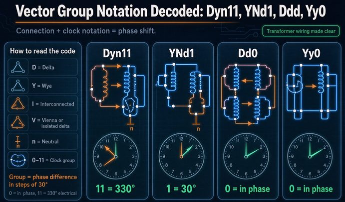
Dyn11, YNd1, Dd0 and Yy0 are four clock readings, not four designs. The capital letter is the high side, the lowercase is the low side, the n is a neutral brought out to a bushing, and the number is a 30 degree step that was decided in the winding shop. Two units with different numbers on one bus carry 4.5 times rated current.
The four symbols, side by side
Start with the thing that actually differs between them, because it is not the letters. All four are three-phase, all four are two-winding, and three of the four are things you can buy off a shelf this month. What separates them is which winding has the neutral, and whether the number is odd or even.
| Symbol | High side | Low side | Neutral | Clock | Low side vs high side | Where you meet it |
|---|---|---|---|---|---|---|
| Dyn11 | delta | star | low side, lowercase n | 11 | 30 degrees ahead (330 behind) | 480Y/277 and 400/230 distribution, worldwide |
| YNd1 | star | delta | high side, capital N | 1 | 30 degrees behind | generator step-up, North America |
| Dd0 | delta | delta | none on either side | 0 | in phase | industrial three-wire, twelve-pulse pairs |
| Yy0 | star | star | none written | 0 | in phase | three-wire only, rare as written |
Two of the four are odd and two are even. Two bring a neutral out and two do not. And in the first two rows the neutral is on opposite sides of the transformer, which is the whole reason one is a distribution unit and the other is a step-up unit.
That table is also where the first argument starts, because the last row is a notation problem. Yy0 has no n. That means neither neutral is brought out to a terminal, and a transformer with no brought-out neutral cannot supply a four-wire service at all. The group that actually runs on distribution systems is Yyn0, with the lowercase n. One letter is the entire product, and it is missing from a lot of drawings.
The letters, once
D and d are delta. Y and y are star, which IEC calls star and North America calls wye, same thing. Z and z are zigzag, which is two half windings per phase on different limbs. Capital is the higher voltage winding, lowercase is the lower, and that holds regardless of which side the power flows through. A step-up transformer still writes its high side first, so a generator step-up is YNd and not Dyn, even though the generator is the source.
N and n are the neutral brought out. Nothing else. That point gets its own section below because it is the most expensive misreading in the whole notation.
The trailing number is the phase displacement in units of 30 degrees, measured from the high side to the low side on a clock face where the high side sits at twelve.
The letter a, and the one group that reads zero
There is one more letter in the standard that almost never appears in a catalog, and it means autotransformer. A symbol like YNa0 is a star connected autotransformer with the neutral brought out, and the a tells you the two windings share turns instead of being separate.
Autotransformers come with clock numbers of 0 or 6 and almost nothing else, because the two windings are the same copper. There is no separate secondary to displace, so there is no angle to choose. Which means a YNa0 and a Dyn11 are not variations on a theme. One is a two-winding transformer with galvanic isolation, and one is a single winding with a tap. The fault current, the impedance, and the isolation all differ, and the notation says so with one lowercase letter that is easy to read past.
If a nameplate has an a in it and the purchase order does not say autotransformer, stop and check. Autotransformers do not isolate, and the classic failure is an autotransformer specified where isolation was required, discovered when somebody tries to establish a separately derived system on the low side and finds there is no separation to establish.
The thirty degrees is geometry, not a convention
Most explanations treat the 30 degree offset as a rule someone chose. It is not. It falls out of the two connections, and once you see it you stop expecting to be able to fix it at the terminals.
Take a 480Y/277 winding. Phase A to neutral is 277 volts at zero degrees. The line-to-line voltage from A to B is the vector difference of two 277 volt phasors 120 degrees apart, which is 480 volts, and its angle is plus 30 degrees from the phase A phasor. The square root of three and the 30 degrees are the same fact stated twice. You cannot have the magnitude without the angle.
Now take a delta. The winding sits directly across two line terminals, so the line-to-line voltage is the winding voltage with no factor and no rotation. If that winding is on the same limb as the star winding above, its voltage is at zero degrees.
star  : 277 V phase at 0 deg  ->  480 V line at +30 deg
delta : 277 V winding at 0 deg ->  277 V line at   0 deg
difference in angle   = 30 deg
difference in magnitude = 1.7321
Put one of each in the same transformer and the low side is going to sit 30 degrees away from where the high side would have put it. That is not a manufacturing choice. It is what the two connections do.
Which gives a rule you can use as a check. Any transformer with a delta on one side and a star on the other is displaced by an odd multiple of 30 degrees, so its clock number is odd. Any transformer with the same connection on both sides is displaced by a multiple of 60, so its clock number is even. A zigzag behaves like a star for this purpose when it is paired with a delta, and like a delta when it is paired with a star, so Dzn gives even numbers and Yzn gives odd.
There is exactly one degree of freedom left after the geometry, and it is which side of the 30 degrees you land on. That is, plus 30 or minus 30. The factory picks it with winding polarity and terminal order, and it is fixed before the tank is closed.
Which leads to the sentence that matters for anyone replacing a unit: you cannot change the clock number by re-landing cables. Swapping two low side cables rotates all three phases by 120 degrees, which moves the number by four hours and also reverses the phase rotation. It does not give you the other 30 degrees. It gives you a different transformer with the wrong rotation.
Lead or lag: the argument that is not one
Here is the sentence that generates more confusion than anything else in this subject, and it appears on the same page twice, in opposite directions, on one of the better ranked references.
Dyn11 means the low side leads the high side by 30 degrees. Dyn11 also means the low side lags the high side by 330 degrees. Both are true statements about the same transformer.
The arithmetic is one subtraction. Eleven hours times 30 degrees is 330 degrees. A full turn is 360. The difference is 30. So “330 behind” and “30 ahead” are the same position on the circle, the way minus 30 and plus 330 are the same angle.
| Clock | Displacement | Same thing said the other way |
|---|---|---|
| 0 | 0 | in phase |
| 1 | 30 behind | 330 ahead |
| 2 | 60 behind | 300 ahead |
| 3 | 90 behind | 270 ahead |
| 4 | 120 behind | 240 ahead |
| 5 | 150 behind | 210 ahead |
| 6 | 180 behind | anti-phase |
| 7 | 210 behind | 150 ahead |
| 8 | 240 behind | 120 ahead |
| 9 | 270 behind | 90 ahead |
| 10 | 300 behind | 60 ahead |
| 11 | 330 behind | 30 ahead |
The standard defines the number as a lag. IEC 60076-1 sets the high side phasor at twelve and reads the low side phasor clockwise, and clockwise is behind. So eleven means the low side phasor sits at the eleven o’clock position, which is 330 degrees clockwise from twelve, which is 30 degrees short of a full turn.
Where people go wrong is not in the arithmetic. It is in writing “Dyn11 means the low side lags by 30 degrees.” That sentence is internally consistent, sounds right, and describes a different transformer. Dyn1 is the one that lags by 30. Dyn11 lags by 330. The number 11 and the number 30 are not interchangeable, and a relay setting or a commissioning note that swaps them will send a technician looking for a fault that is not there.
So the rule to carry: the number is always a lag. If you want to say “leads”, do 360 minus the number times 30 first, and say the result out loud. Nobody gets 330 wrong. Plenty of people get “Dyn11 lags 30” wrong.
One more wrinkle worth knowing before the next section. The clock number is defined for positive phase sequence with the high side terminals taken in alphabetical order. Reverse the rotation and the same physical unit measures 30 degrees the other way. That is a statement about the reference, not about the iron. It also means two units that both say Dyn1 are compatible with each other in either rotation, while a Dyn1 and a Dyn11 are never compatible, because the 60 degrees between them survives the reversal.
The number is defined against the terminal marking
A detail that bites anyone reading two standards at once. The displacement is defined relative to terminal designations, and the two standards designate terminals differently.
| Convention | High side lines | High side winding ends | Low side lines | Low side winding ends |
|---|---|---|---|---|
| IEEE C57.12.70 | H1, H2, H3 | H1-H2, H2-H3, H3-H1 | X1, X2, X3 | X1-X2 and so on |
| IEC 60076-1 | 1U, 1V, 1W | 1U1-1U2 | 2U, 2V, 2W | 2U1-2U2 |
| Older IEC and much of Asia | A, B, C | A-X, B-Y, C-Z | a, b, c | a-x, b-y, c-z |
IEEE C57.12.00 states the displacement as the low side at X1 lagging the high side at H1 by 30 degrees. In IEC language the same sentence is written against 1U and 2U. Both describe a position on the same clock, and a unit built to one convention can be described correctly in the other, but the labels on the hardware will not match a drawing done in the other system.
That matters because the three voltmeter check later in this article is done phase to phase, and the person holding the meter has to know which bushing is X1 on a unit marked 2U1. The mapping is one to one, it is on the connection diagram, and it is not on the transformer.
Odd and even: a parity check that catches typos
Because the parity follows from the connection, it works backwards as a proofreading tool, and almost nobody uses it that way.
If the symbol has five characters and the last two are 10, the symbol is wrong. Dyn10 cannot exist. Neither can YNd12, Dd11, or Yy7. The number has to be in the right parity for the letter pair, and the parity is set by whether the two sides are the same family.
| Letter pair | Parity | Real examples | Impossible |
|---|---|---|---|
| Yy, Dd, Dz | even | Yy0, Dd0, Dd6, Dzn0 | Dd5, Yy11 |
| Dy, Yd, Yz | odd | Dyn11, Dyn1, YNd5, Yzn11 | Dyn0, YNd6 |
This catches more real mistakes than you would expect, because the errors are usually transcription errors between a datasheet, a purchase order, and a nameplate. A buyer retyping YNd11 as YNd1 is not a parity error and will not be caught this way, but a buyer retyping Dyn11 as Dyn12 will be caught in under a second.
The parity rule also answers a question that comes up in every review: why can I not have a Dyn0? Because a delta and a star cannot be in phase. The 30 degrees is built into the windings. If you want zero displacement you need the same connection on both sides, which is Yy0 or Dd0.
The 30 degrees is invisible to every load
Worth saying plainly, because it saves a lot of unnecessary worry. A 30 degree displacement does not affect anything fed from a single transformer.
A three-phase induction motor does not know where zero degrees is. It responds to phase sequence and magnitude, and a 30 degree rotation of all three phases is indistinguishable from a rotation of the reference the motor is measured against. A rectifier does not care. A panelboard does not care. A power meter does not care, beyond the phase angle it reports for power factor, which will read 30 degrees off if it was commissioned against a different reference.
The displacement becomes visible only where two sources meet. That is a short list, and every item on it is a place where somebody has to know the number before the breaker is closed.
| Interface | Why the angle matters | What goes wrong |
|---|---|---|
| Two transformers in parallel | the low side voltages have to coincide | circulating current, 4.5 per unit at 30 degrees |
| Closed transition transfer | both sources must be in phase at the make | current spike at the make, main trips |
| Differential protection | the shift has to be compensated in the relay | 51.8 percent slope, operates at any load |
| Generator synchronising | the unit shift is part of the angle the synchroscope sees | out of phase close, or a refusal to close |
| A tie breaker with a synch check element | the element compares two voltage angles | somebody defeats the element to get the plant running |
| Negative sequence directional | the shift reverses in negative sequence | element sees a forward fault as reverse |
Everything outside that table runs identically on a Dyn11 or a Dyn1, which is why both exist and why nobody notices the difference until two units have to share a bus. It is also why a plant can run for twenty years on a mixed set of vector groups and discover the problem on the day somebody closes a tie for the first time.
One arithmetic note that follows from the same idea. The shift is multiplied by the harmonic order, so a 30 degree fundamental displacement is 150 degrees at the fifth harmonic and 210 at the seventh. That is why the clock number alone does not predict how two harmonic-rich sources will combine, and why harmonic cancellation is designed from the rectifier topology and not from the vector group.
Why Dyn1 exists at all
This is the part that makes the whole subject look arbitrary, and it is not. Two standards bodies settled on opposite defaults.
IEEE C57.12.00 fixes the displacement for standard North American units. With standard terminal markings, delta-delta and wye-wye units have no displacement, and for delta-wye and wye-delta units the low side line-to-neutral voltage at terminal X1 lags the high side at H1 by 30 degrees in positive sequence, whichever winding is the delta. Read that as a requirement, not a description. In IEC terms, a standard North American substation transformer is Dyn1, and a standard step-up transformer with a grounded wye high side is YNd1.
IEC 60076-1 defines how to write the symbol. It does not tell you which one to build. So a European or Asian factory, left to its own convention and the natural way of closing a delta, produces 11. Not because 11 is better. Because nothing told it to produce 1.
| Market | Governing document | Distribution unit | Step-up unit | Note |
|---|---|---|---|---|
| North America | IEEE C57.12.00 | Dyn1 | YNd1 | the 30 degree lag is a requirement |
| Europe, Asia, Africa, Middle East | IEC 60076-1 | Dyn11 | YNd11 | both directions permitted |
| Germany, Austria | DIN and VDE practice | Dyn5 | YNd5 | historical, regionally codified |
The consequence is a specific and recurring procurement failure. Dyn11 is the most common three-phase distribution transformer in the world by unit count, so it is the default in most datasheets, most catalogs, and most of the internet. It is not the default in North America. A specification that says “standard vector group” means two different things on two continents, and the number itself is never ambiguous, which is exactly why the ambiguity hides.
If you are buying in the United States or Canada and the existing plant is Dyn1, writing Dyn11 on the purchase order is not a rounding error. It is a different unit that will not parallel with anything you own.
YNd1 and YNd11: same iron, sixty degrees apart
The step-up pair gets its own section because the 60 degrees between them is larger than the 30 that most people worry about, and because the substitution question comes up constantly when a generator transformer fails.
| Symbol | Standard and region | Low side | Difference from the other |
|---|---|---|---|
| YNd1 | IEEE, North America | 30 behind | reference |
| YNd11 | IEC, Europe and Asia | 30 ahead | 60 from YNd1 |
| YNd5 | DIN and VDE, Germany and Austria | 150 behind | 120 from YNd1 |
All three do the same job for the generator, which is to keep zero-sequence current out of the stator. The delta on the low side gives that current a closed loop inside the transformer, so an external ground fault on the high side circulates in the delta instead of passing through the generator windings. That part is identical in all three, and it is the reason a step-up transformer is YNd rather than YNy in the first place.
The difference is only the clock number, and the clock number is 60 degrees between the two you will actually encounter.
Sixty degrees is not a labeling preference. It is the difference between two units whose secondaries cannot be connected together, and it is not recoverable at the terminals. A published paper on substituting large power transformers in generating stations puts it plainly: it is normally not possible to substitute a unit with vector group 11 for one with vector group 1, or the reverse. Not difficult. Not expensive. Not possible, short of a phase-shifting transformer or a rewind.
There is one escape that gets mentioned in that paper and is worth knowing, because it explains a lot of confusion. A standard Dy1 unit with the phase sequence externally reversed on both sides is equal to Dy11 in behavior. That sounds like a loophole and it is not one for a substitution, because reversing rotation on both sides of an existing plant means every motor in the building turns backwards.
The n does not mean grounded
Six of the sources on the first page of this query say some version of “Dyn11 provides a grounded neutral” or “provides a defined earth reference.” That is not what the letter means, and the misreading costs money.
The lowercase n means the neutral point of the low side star is brought out to a bushing. It is a statement about a terminal, not about a connection to earth. A Dyn11 transformer with the neutral bushing sitting in free air, connected to nothing, is still a Dyn11. A YNd1 with a resistance grounded high side neutral is still a YNd1. The symbol does not change when you change the grounding.
Grounding is a system design decision made by somebody else, usually the utility or the plant engineer, and it has four common answers: solid, low resistance, high resistance, or ungrounded. The transformer has to be built to survive whichever one applies, which is a matter of neutral insulation level and not a matter of the vector group.
Where this goes wrong in practice is at the boundary between the two. Someone reads Dyn11 on a datasheet, concludes the neutral is grounded, designs a four-wire service off it, and then discovers one of two things at commissioning. Either the neutral bushing is there with no grounding conductor specified, or the unit was built with reduced neutral insulation because the designer assumed it would be solidly grounded, and the system turns out to require resistance grounding with a higher neutral voltage during a fault.
The second one is the expensive version. Reduced neutral insulation is a legitimate cost saving on a solidly grounded unit and a liability on anything else, and the vector group does not tell you which one you have.
The same logic applies to the capital N on YNd1. It means the high side neutral is brought out. On a generator step-up transformer that bushing is usually solidly grounded, sometimes impedance grounded, and occasionally left available for a grounding transformer downstream. The symbol covers all three.
Corner grounded delta
A delta winding can be grounded at one corner, and the result is still written Dd0. The symbol does not record it.
Corner grounding appears on industrial systems because it gives a ground reference with no neutral at all. It also makes a single line to ground fault look like a line to line fault to the overcurrent protection, which trips faster and at a lower current. The cost is that the two ungrounded phases sit at full line voltage above ground, so every conductor, bushing and device on those phases needs line to line insulation instead of line to ground.
Buying a Dd0 for a corner grounded system means buying a delta with a specific insulation coordination, and the five characters do not say which one you got. It has to be on the drawing.
Center tapped delta
The same silence applies to a center tapped delta, which is the high leg or stinger arrangement. It is also written Dd0, or sometimes as a delta with a note, and it delivers 120 volts from two corners to the center tap and 208 volts from the third. The symbol does not record the tap.
That is the more dangerous of the two omissions. A center tapped delta looks like a 240 volt delta on the nameplate and delivers 208 volts on one leg, and the load that gets landed on the wrong leg is usually a control transformer or a starter coil that fails within minutes of energization.
What a wrong number costs on a shared bus
Now the part that the ranking pages either skip or get wrong by a factor of seventeen.
When two transformers are paralleled and their low side voltages are not in phase, the difference between those voltages drives a current around the closed loop formed by the two secondaries. The loop contains only the two leakage impedances, so the current is large. The driving voltage for a displacement of delta is the vector difference of two equal magnitudes, which is twice the sine of half the angle.
I_circ (per unit) = 2 * sin(delta / 2) / (z1 + z2)That denominator is the entire story, and it is the thing the wrong answers omit. A 30 degree displacement produces 0.518 per unit of driving voltage. Divide that by two impedances of 5.75 percent each, which is 0.115 per unit, and the circulating current is 4.50 per unit. Not 51.8 percent. Not 25.9 percent. Four and a half times rated current, continuously, with no load on the bus.
| Displacement | Driving voltage, pu | Circulating current, pu | Amps on 1,000 kVA at 480 V | Force, times rated |
|---|---|---|---|---|
| 30 degrees | 0.5176 | 4.50 | 5,414 | 20.3 |
| 60 degrees | 1.0000 | 8.70 | 10,459 | 75.6 |
| 120 degrees | 1.7321 | 15.06 | 18,116 | 226.8 |
| 180 degrees | 2.0000 | 17.39 | 20,918 | 302.5 |
Two things in that table are worth pausing on.
The first is the last row. Seventeen point three nine per unit is exactly the bolted fault current for a 5.75 percent unit, one over 0.0575. That is not a coincidence. Two per unit of driving voltage across two impedances of Z is one over Z in the loop, which is the same expression as a fault across one of them. A 180 degree mismatch is a bolted fault through both transformers, permanently, with the breakers closed.
The second is the force column, which is the current squared. At 30 degrees the windings see twenty times rated electromagnetic force. At 60 degrees it is seventy six times. Transformers are built to take the forces of a through fault at their terminals, which for this impedance is 302 times rated, so none of these numbers exceeds the mechanical design. That is the uncomfortable part. A 30 degree mismatch does not destroy the transformer in one cycle. It heats it, and the protection takes its time.
Change the impedances and the numbers move, but not much. Two units at 6 percent give 4.31 per unit at 30 degrees. A 5.75 and a 6.5 give 4.23. The table is not sensitive to the impedance spread; it is sensitive to the angle.
The smaller unit takes the bigger multiple
Mix sizes and the arithmetic gets worse for the little one, which is not obvious from the nameplate.
A 1,000 kVA and a 500 kVA unit, both at 5.75 percent on their own base, paralleled with 30 degrees between them. On a 1,000 kVA base the second unit’s impedance is 0.115 and the sum is 0.1725, so the circulating current is 3.00 per unit of the 1,000 kVA rating, which is 3,609 amps. Against the 500 kVA unit’s own full load current of 601 amps, that same 3,609 amps is six times its rating.
| Pairing | Circulating current | On the large unit | On the small unit |
|---|---|---|---|
| 1,000 + 1,000, both 5.75% | 5,414 A | 4.50 pu | 4.50 pu |
| 1,000 + 500, both 5.75% | 3,609 A | 3.00 pu | 6.00 pu |
| 1,000 + 250, both 5.75% | 2,166 A | 1.80 pu | 7.20 pu |
A 250 kVA unit in parallel with a 1,000 at 30 degrees sees seven times its rated current. It will not survive the afternoon, and the larger unit will look fine while it happens, which is a difficult thing to explain to whoever sized the pair.
Why the protection does not tell you
This is the question that gets asked after the fact, and the answer is that the differential relay is working correctly when it does nothing.
The circulating current is a real power transfer between two transformers. Current leaves one secondary and enters the other, and in each transformer the high side current rises to match, so ampere-turns balance on both sides of both units. Each differential zone sees a balanced through-current of four and a half times rated. There is no differential current to see, because nothing is faulted. The relay is doing exactly what it was built to do.
The instantaneous element does not see it either, because 4.5 times is below the six to ten times pickup that a transformer main is usually set at to ride through inrush.
Which leaves the time-overcurrent element, and it does operate. The problem is what it looks like when it does. Two transformers, both energized, tie closed, no load, and four and a half times rated current flows for a few seconds until the long-time element times out. The plant saw a main breaker trip with nothing connected. The natural diagnosis is a bad breaker or a bad relay, and the natural first response is to raise the setting.
That is how a two-minute arithmetic error becomes a destroyed transformer. The second close is at a higher setting, the current flows longer, and the winding that was merely hot is now damaged.
| Relay element | Sees | Acts |
|---|---|---|
| Transformer differential | balanced through-current | holds, correctly |
| Instantaneous overcurrent | 4.5 pu, below pickup | holds |
| Time overcurrent | 4.5 pu | trips in seconds, no load on the bus |
| Winding temperature | rising | alarm, then trip, if fitted |
The 30 degrees in the relay settings
Even when the vector group matches, the number has to get into the protection, and there are two places it can go wrong.
The first is the setting itself. A digital relay is told the vector group and compensates in software. Give it clock 1 when the unit is clock 11 and the error is not 30 degrees, it is 60, because the relay rotates the wrong way. An uncompensated 30 degrees produces a differential quantity of 0.518 per unit with a restraint of 1.0, which is a slope of 51.8 percent. Any relay set at 25 or 40 percent slope operates. At 60 degrees the differential quantity is 1.0 per unit, the slope is 100 percent, and the relay operates at any load at all, including no load.
| Displacement seen by the relay | Differential quantity, pu | Slope on an average restraint | Result |
|---|---|---|---|
| 15 degrees | 0.261 | 26.1% | marginal, trips on some settings |
| 30 degrees | 0.518 | 51.8% | trips on any normal slope |
| 60 degrees | 1.000 | 100.0% | trips at no load |
The second is where the current transformers sit. On a Dyn11 the high side is the delta, so the line current and the winding current differ by the square root of three. On a 1,000 kVA 12.47 kV unit the line current is 46.3 amps and the current inside the delta is 26.7 amps. Current transformers in the line see 46.3. Current transformers inside the delta see 26.7, and the relay has to be told to put the 1.732 back. Forget it and the differential sees a 42 percent mismatch at full load, which is right at the boundary where some slope settings operate and some do not. That is the worst place for an error to live, because it produces intermittent trips that nobody can reproduce.
Something the vector group does to fault analysis
One more consequence that does not show up in any of the ranking pages. The 30 degree shift reverses in negative sequence.
Positive sequence current crossing a Yd transformer shifts by plus 30 degrees. Negative sequence current crossing the same transformer shifts by minus 30. That is why symmetrical component fault analysis treats the two networks with opposite rotations, and it is why a negative-sequence directional element has to be told the vector group. Get it wrong and the element sees a forward fault as reverse. On a transformer with a 11 group and a relay configured for 1, both the magnitude and the direction of every negative-sequence quantity are wrong.
Dd0 and Yy0: the two that are not distribution transformers
Neither of these belongs on a four-wire service, and both have a legitimate job.
Dd0 has no neutral anywhere, which is not a defect in a three-wire industrial system. It blocks zero sequence in both directions, so neither side sees the other’s ground faults, and it is the group that can keep running on two units in open delta if one fails. It is also half of a twelve-pulse rectifier.
That last point is worth a paragraph because it is the clearest demonstration that the clock number is a tool and not a label. A twelve-pulse rectifier needs two three-phase supplies 30 degrees apart, so that the fifth and seventh harmonics from one bridge cancel the fifth and seventh from the other. Dd0 puts the low side at zero degrees. Dy11 puts it at 330, which is 30 degrees the other way. Put them on the same core, fed from one primary, and you have 30 degrees and a twelve-pulse unit. Two Dd0 secondaries give zero degrees between them, which is a six-pulse unit with twice the copper and no cancellation at all. The same letters, a different number, and the harmonic performance is the entire difference.
Yy0 is the one to be careful with, and the caution starts with the spelling.
| Written | Neutral brought out | Can supply four-wire | What it actually is |
|---|---|---|---|
| Yy0 | neither side | no | three-wire star-star, rare |
| Yyn0 | low side | yes, if grounded | the distribution unit people mean |
| YNyn0 | both sides | yes | transmission and autotransformer ties |
A Yy0 with no neutral cannot feed a 120 volt load. If a drawing says Yy0 and the intent was a 480Y/277 service, the drawing is wrong by one letter and the purchase order will follow it.
Even as Yyn0, the star-star connection has a zero-sequence problem that a delta does not. There is no closed path for zero-sequence current inside the transformer, so it has to return through the tank, and the zero-sequence impedance ends up several times the positive-sequence value. The practical result is neutral displacement under single-phase load, and a third harmonic voltage in the phase-to-neutral waveform because the magnetizing triplen has nowhere to go.
| Single-phase load | Dyn11, neutral shift | Yyn0, neutral shift | Yyn0 in volts on 277 |
|---|---|---|---|
| 20 percent | 0.38 percent | 3.83 percent | 10.6 V |
| 30 percent | 0.57 percent | 5.75 percent | 15.9 V |
| 50 percent | 0.96 percent | 9.58 percent | 26.5 V |
Those numbers assume a zero-sequence impedance ten times the positive-sequence value for the star-star, which is typical for a three-limb core and would be worse without a delta path. The delta-wye column is close to the positive-sequence value because the delta closes the loop.
That table is the reason a star-star distribution transformer is usually a star-star with a delta tertiary, which brings us to the parentheses.
The letter in the parentheses
A symbol like YNyn0d5 has a fifth element, and it is a real winding.
The d5 is a delta connected stabilising tertiary, and the 5 is its clock number relative to the high side. It is usually rated at a third of the main kVA, it is sometimes brought out to bushings and sometimes buried inside the tank, and it exists to give zero-sequence and triplen current somewhere to circulate so the star-star connection behaves itself.
It is also invisible in most of the documentation a buyer sees. A datasheet that says YNyn0 and a nameplate that says YNyn0d5 describe two different transformers, and the difference matters for harmonics, for unbalanced load, and for whether the unit has a spare winding you could use for station power.
Three questions to ask, and none of them are answered by the vector group alone:
- Is there a tertiary at all. A star-star without one is a different product from a star-star with one.
- What is it rated. One third of the main kVA is common practice, not a rule. A tertiary rated at a sixth will run out of circulating current capacity at a lower triplen content.
- Is it brought out. A buried tertiary cannot be used, tested, or loaded. A brought-out one can, and it changes the termination arrangement and the price.
What the vector group does not tell you
The symbol is five characters. It is a complete description of one thing and a silent omission of about a dozen others, and buyers routinely treat it as a summary of the whole unit.
Not in the symbol:
- percent impedance, which sets the fault current and the load sharing
- voltage ratio, beyond the connection
- kVA rating
- cooling class, and whether it is ONAN, ONAF, or dry type
- tap range and tap steps
- basic impulse level
- no-load and load losses
- sound level
- terminal and bushing arrangement
- whether the neutral is grounded
- whether a tertiary exists
- the impedance angle, which matters for paralleling as much as the magnitude
Two units both stamped Dyn11 can differ in every one of those. The vector group tells you they are in phase and have the same shape of connection. It tells you nothing about whether they can share a load.
One related point that surprises people: taps do not move the clock number. An off-circuit tap changes the number of turns, so each 2.5 percent step moves the ratio by 2.5 percent, but the phase displacement is set by the connection and does not move at all. A Dyn11 stays Dyn11 on every tap position. What taps do change is the paralleling arithmetic, because two units on different tap positions have different no-load voltages and will circulate current for that reason instead of for an angle reason.
That distinction matters at commissioning, because a ratio mismatch and an angle mismatch look similar on a voltmeter and have completely different fixes.
What to write on the purchase order
Five characters are not a specification. Here is what has to be on the order in addition to the symbol, because these are the things that make two units with the same vector group incompatible anyway.
| Field | Why it is on the list | What happens without it |
|---|---|---|
| Vector group, five characters | the phase relationship | a unit 60 degrees away arrives |
| Percent impedance and tolerance | load sharing and fault current | one unit overloads at 94 percent of bank rating |
| Tap range and step size | ratio matching at commissioning | circulating current from a ratio error |
| Neutral insulation level | the grounding method | reduced insulation on a resistance grounded system |
| Tertiary, if any, and its rating | zero sequence and station power | a buried winding nobody can use |
| Terminal marking convention | which bushing is X1 | cables landed to the wrong phase |
| Phase rotation convention | the clock number is defined against it | every angle measured afterwards is meaningless |
Two rows get left off more than the rest. Impedance gets left off because the supplier will pick one and it will be close. Neutral insulation gets left off because nobody thinks about it until the grounding study is finished, which is normally after the order is placed.
An order that reads “1,000 kVA, 12.47 kV to 480Y/277, Dyn11, 5.75 percent, plus and minus two 2.5 percent taps, neutral insulation rated for line to neutral only, no tertiary, H1 to X1 marking” is a specification. An order that reads “Dyn11” is a wish.
Commissioning: three checks
The vector group on the nameplate is a claim. These are the three things that verify it, in the order they have to be done.
First, the nameplate match. Both units, both sides, all five characters. This is necessary and it is not sufficient, because nameplates get stamped from the wrong drawing and because a unit can be internally reconnected after the nameplate is fitted.
Second, phase rotation, on both sides. This comes before any angle measurement, because the clock number is only defined for positive sequence. If the rotation is reversed on one side, every angle you measure afterwards is meaningless and the transformer will look wrong when it is right. A rotation meter on the high side and on the low side, recorded, before anything else.
Third, three voltmeters across the open tie. With both transformers energized and the tie breaker open, measure the voltage between corresponding phases on the two sides of the open breaker. Three readings, all of them zero, is the only pass.
| Displacement | Reading on each of the three phases | As a fraction of 480 V |
|---|---|---|
| 0 degrees | 0 V | 0 |
| 30 degrees | 248.5 V | 51.8 percent |
| 60 degrees | 480.0 V | 100 percent |
| 120 degrees | 831.4 V | 173 percent |
| 180 degrees | 960.0 V | 200 percent |
All three readings equal is the signature of a pure displacement, because a phase shift rotates all three phases by the same amount. Unequal readings point somewhere else, usually at a ratio difference or at one phase landed wrong, and the fix is different.
A 60 degree mismatch reads a full 480 volts on each phase with both transformers energized and nothing connected. That is the most common wrong-pair signature in the field, and it is also the one that gets misdiagnosed as a ratio problem, because 480 volts is a number people recognize.
A replacement that cannot be made to work
Put the pieces together on a real scenario, because the arithmetic is more persuasive than the rule.
A plant in Ohio runs two 1,000 kVA, 12.47 kV to 480Y/277 units in parallel. Both are stamped Dyn11, imported years ago on a project specification that came from Europe. One fails. The local supplier quotes a stock unit, correctly built to IEEE C57.12.00, which makes it Dyn1.
Six characters differ. The voltages match, the kVA matches, the impedance is within a tenth of a percent, and the two units are 60 degrees apart.
From the table above, 60 degrees is 8.70 per unit of circulating current, which on this rating is 10,459 amps, with 75.6 times rated force in both windings. Nothing needs to be calculated beyond that. The tie cannot be closed.
The options are narrower than they look.
- Order a Dyn11 unit. Correct, and it costs the lead time, which for a 1,000 kVA dry type is weeks to months depending on the factory. This is the answer most of the time.
- Run the new unit on its own bus section with the tie open and interlocked. Works, and it means the plant no longer has N+1 capacity. It has two half-plant feeds, and a fault on one takes out half the building.
- Install a phase shifting transformer ahead of the new unit. Technically possible, rarely economic at this rating, and it adds a device that can fail.
What is not on the list is re-landing cables, swapping two phases on one side, or asking the factory to “change the vector group.” None of those produce 60 degrees.
The unit itself is not defective. A Dyn1 is exactly the right transformer for a North American system built to C57.12.00. The mistake was made on the purchase order, years of lead time before the failure, and it only becomes visible when two units have to share a bus.
Six things that go wrong
These are the ones I see repeatedly, roughly in order of how much they cost.
- “Dyn11 means the low side lags by 30 degrees” in a commissioning note. It lags by 330. The note sends a technician to look for a 30 degree error that is not there, and the real setting gets changed to compensate for a fault that does not exist.
- A Yy0 ordered for a four-wire service. The missing n means no neutral terminal, so there is no 277 volt output and the unit is a three-wire star-star. The drawing and the purchase order both said Yy0, so nobody catches it until the service is installed.
- A Dyn1 substituted for a Dyn11 because the kVA and voltage matched. Covered above. The 60 degrees is not negotiable and it is not visible on a datasheet that lists only kVA, ratio, and impedance.
- Current transformers landed inside the delta without the 1.732. The relay sees a 42 percent mismatch at full load, which sits right at the slope boundary and produces trips that come and go with load.
- A main breaker tripping at no load, diagnosed as a breaker problem. The circulating current is real and the differential relay was right to hold. Raising the setting converts a nuisance trip into a burned winding.
- A tertiary assumed because the datasheet said YNyn0. The nameplate says YNyn0d5, the tertiary is buried, and the station power feed that was designed around it has nowhere to connect.
Every one of these is a reading error on five characters, and every one of them is checkable before the order is placed.
FAQ
What does Dyn11 mean in plain English?
High side is delta, low side is star with the neutral brought out, and the low side voltage sits 330 degrees clockwise from the high side, which is the same as being 30 degrees ahead of it. The 11 is a clock position, not a ratio and not a percent.
Is 11 a lead or a lag?
Both, and that is not a contradiction. Eleven times 30 is 330, so the low side lags by 330 degrees, which is 30 degrees short of a full turn and therefore 30 degrees ahead. The standard defines the number as a lag. If you write “lags by 30” you have described Dyn1.
Can a Dyn11 and a Dyn1 be paralleled?
No. They are 60 degrees apart. At 5.75 percent impedance each, that drives 8.70 times rated current around the loop with no load connected, and nothing in the protection package is set to catch it before the windings heat. There is no cable rearrangement that closes 60 degrees.
Why is Dyn11 more common than Dyn1?
Because most of the world builds to IEC 60076-1, which specifies how to write the symbol but not which one to build, and the natural way of closing a delta gives 11. IEEE C57.12.00 does specify, and it requires the low side to lag by 30 degrees, which is 1. Unit count favors 11. North American practice favors 1.
What does the lowercase n mean?
The neutral point of the low side star winding is brought out to a terminal. It says nothing about whether that terminal is grounded, what it is grounded through, or what the neutral insulation is rated for. Those are system design decisions that the vector group does not record.
Does Dyn11 mean the neutral is grounded?
No. A Dyn11 with the neutral bushing connected to nothing is still a Dyn11. Grounding is decided by the system design, and the transformer is built to suit it, usually by adjusting the neutral insulation level. Buying on the assumption that n means grounded is how reduced insulation ends up on a resistance grounded system.
What is YNd1 used for?
Generator step-up, mostly in North America. The high side is star with the neutral brought out so it can be grounded at the transmission voltage, and the low side is delta so zero-sequence current from an external ground fault circulates inside the delta instead of passing through the generator stator. YNd11 does the same job in IEC markets, 60 degrees away.
Can Yy0 be used for a four-wire service?
No, and the reason is the missing n. Yy0 has no neutral brought out on either side, so there is no terminal for a 277 volt load. The group that runs on four-wire distribution is Yyn0. If a drawing says Yy0 and the intent was a four-wire service, the drawing is wrong by one letter.
What is Dd0 used for?
Three-wire industrial systems where no neutral is needed, and as half of a twelve-pulse rectifier. Dd0 puts the low side at zero and Dy11 puts it at 330, so pairing them produces the 30 degrees that cancels the fifth and seventh harmonics. Two Dd0 secondaries give zero degrees between them and cancel nothing.
How much current flows if the vector groups do not match?
Take twice the sine of half the angle, divide by the sum of the two per unit impedances. Thirty degrees is 0.518 divided by 0.115, which is 4.5 times rated. Sixty degrees is 8.7 times. One hundred eighty degrees is 17.4 times, which is exactly the bolted fault current for a 5.75 percent unit.
Why did my differential relay not trip?
Because there was no differential current. The circulating current is a real power transfer between the two transformers, so the high side current rises to match the low side in each unit and ampere-turns balance. The relay sees a balanced through-current of four and a half times rated and correctly holds. The time overcurrent element is the one that eventually operates.
Can I change the vector group in the field?
No. The clock number is set by winding polarity and terminal order inside the tank. Swapping two low side cables rotates all three phases by 120 degrees and reverses the phase rotation, which does not produce the other 30 degrees. A unit built to one clock number has to be replaced by a unit built to the same one.