A 480 V to 208Y/120 V commercial transformer is sized by three numbers, and only one of them comes from the load. The other two are the fault current at the 208 V bus and the federal efficiency floor. Get the kVA right and those two wrong, and the panelboard you bought is the wrong class.
| kVA | Primary amps at 480 V | 125 percent device | Secondary amps at 208 V | 125 percent device | Fault current at 208 V, 5.75 percent |
|---|---|---|---|---|---|
| 15 | 18.0 | 25 A | 41.6 | 60 A | 724 A |
| 30 | 36.1 | 50 A | 83.3 | 110 A | 1,448 A |
| 45 | 54.1 | 70 A | 124.9 | 175 A | 2,172 A |
| 75 | 90.2 | 125 A | 208.2 | 300 A | 3,621 A |
| 112.5 | 135.3 | 175 A | 312.3 | 400 A | 5,431 A |
| 150 | 180.4 | 250 A | 416.4 | 600 A | 7,241 A |
| 225 | 270.6 | 350 A | 624.5 | 800 A | 10,862 A |
| 300 | 360.8 | 500 A | 832.7 | 1,200 A | 14,482 A |
| 500 | 601.4 | 800 A | 1,387.9 | 2,000 A | 24,137 A |
Those fault currents assume an infinite primary bus, which is the conservative case and the one to use for a first pass. The real number is lower and the gap widens with size, which is covered further down and matters more than most people expect.
Everything in that table is one multiplication. The interesting part is what happens when those numbers meet a panelboard catalog, a breaker curve, and a federal rule that changed in 2029 and is already on the books.
It is not a service, and that word decides the grounding
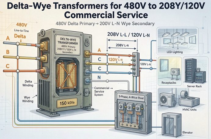
The phrase gets used loosely, so start here. A transformer inside a building that steps 480 V down to 208Y/120 V is not service equipment. Service equipment is what the utility connects to, and it carries a marking that says so. This unit is utilization equipment sitting downstream of the service, and it cannot serve as the service disconnect no matter how it is wired.
That distinction is not pedantry, because it decides which grounding article applies. If this were a service, you would be in 250.24, bonding at the service disconnect and running a grounding electrode conductor to the electrode system. It is not a service, so you are in 250.30, and the secondary is a separately derived system.
What 250.30 asks for
Article 100 defines a separately derived system as premises wiring with no direct connection to the supply conductors of another system, including no solidly connected grounded conductor. A delta primary and a wye secondary share no conductor and no neutral, so the 208Y/120 side is a new system with a new ground reference, even though it sits twenty feet from the gear that feeds it.
Four things have to be true.
The secondary neutral, X0, gets connected to the equipment grounding conductor at exactly one point. That connection is the system bonding jumper, and it lives either at the transformer or at the first disconnecting means, not both.
A grounding electrode conductor runs from that same point to the grounding electrode system.
If the first disconnecting means is in a separate enclosure, a supply-side bonding jumper runs from the transformer to that enclosure, sized from the derived phase conductors under Table 250.102(C)(1).
Downstream of the bonding point, neutral and ground stay separate. The panel neutral bar floats on its insulators, the ground bar bolts to the can, and the green screw that would tie them together stays in the bag.
Two bonds means neutral current divides between the neutral and the equipment grounding conductor, and every metal surface on that feeder carries a share of the return current. That is the failure the code is trying to prevent, and it is the first thing a good inspector looks for.
The jumper size nobody checks
The system bonding jumper and the grounding electrode conductor are both sized from the derived phase conductors, and both tables are one page.
For a 112.5 kVA unit with 600 kcmil copper secondary conductors, Table 250.102(C)(1) puts the bonding jumper at 1/0 copper and Table 250.66 puts the grounding electrode conductor at 1/0 copper. Same answer from both tables, which is a useful coincidence to remember.
Now the part that surprises people. For 1 AWG phase conductors the jumper is 6 AWG, and for 1/0 phase conductors it is still 6 AWG. Not 2 AWG, not 8 AWG. Two of the wiring guides that rank for this topic give 2 AWG for 1 AWG conductors and 8 AWG for 1/0 conductors, which are wrong in opposite directions, and both are published as installation instructions. The table takes thirty seconds to read and it is the difference between a red tag and a passed inspection.
One more bonding rule that gets skipped. If the transformer sits in a different building from the service, or if the electrode system at the transformer is separate, the grounding electrode conductor has to be bonded to the metal raceway or cable armor at both ends if that raceway is ferrous. A single-bonded steel conduit around a grounding electrode conductor is a choke, not a conductor, and it will fail a ground loop impedance test even though every connection is tight.
The 480Y/277 primary that has no neutral to land
Most commercial buildings are served at 480Y/277, so the transformer primary is fed from three phase conductors of a grounded wye system. There is no primary neutral to connect, because a delta winding has no star point. The neutral in that 480Y/277 panel stays where it is.
This is where a surprising number of installs go wrong in a small way. Somebody lands the 480 V neutral on an H0 terminal that does not exist, or bonds the transformer enclosure to the neutral bar instead of the ground bar, and the result is a parallel neutral path on the primary side that serves no purpose and creates a code problem.
The rule is simple. The primary gets three phase conductors and an equipment grounding conductor. Nothing else. The 480Y/277 neutral is not part of this circuit and does not belong in that enclosure.
There is a second consequence worth stating plainly, because it is the reason the delta primary exists at all. Because the primary has no neutral and the winding is closed, zero sequence current from the 480 V side cannot cross into the transformer. The 208Y/120 system is isolated from the 480 V grounding in the only way that matters, which is why the secondary can be a new grounded system rather than an extension of the old one.
The disconnect that is not the breaker
NEC 450.14 requires a disconnecting means in the primary circuit for transformers, and it has to be within sight of the transformer or capable of being locked in the open position.
On a lot of jobs the 480 V breaker is in a panel two rooms away and has no lockout provision on the handle. That is a 450.14 violation even though the breaker is a perfectly good overcurrent device, and it shows up as a punch list item at the end of the job when the electrician has already pulled wire.
The cheap fix is a non-fused disconnect within sight, ahead of the transformer. The expensive fix is a lockable breaker operating mechanism on the existing panel, which usually costs more than the disconnect and takes longer to arrive.
Sizing from the panel schedule
The kVA comes from a load calculation, and the load calculation is where most of the argument happens. This section is about the part after the argument, when you have a number and need to turn it into a purchase order.
What the load calculation has to give you
For a new building, Article 220 gives you the method. For an existing building, 220.87 lets you use measured demand instead of a calculated load, and that is almost always the better answer because it is real. The usual form is the maximum demand over a twelve month period from the utility interval data, times 1.25 if you have less than a full year.
That 1.25 is not a safety factor to be argued with. It accounts for the difference between a thirty day window and an annual peak, and removing it because the number looks generous is how buildings end up with a transformer at 98 percent load on the hottest afternoon of the year.
Then 215.2(A)(1) applies to the feeder: conductors and devices sized at 125 percent of the continuous load plus 100 percent of the noncontinuous load. A commercial building is mostly continuous load, so in practice the transformer has to be at least 1.25 times the calculated demand unless you enjoy explaining yourself.
Put those together and a 700 kVA calculated demand wants a 1,000 kVA unit at minimum. That is not a reason to buy 1,500. It is a reason to know which number you are defending, because the transformer is the cheapest part of a service upgrade and the gear downstream is not.
The ladder, and what each size does to your gear
Three phase dry type transformers come in preferred ratings of 15, 30, 45, 75, 112.5, 150, 225, 300, 500, 750 and 1,000 kVA. Anything between those is a custom build with a custom price and a lead time measured in months rather than weeks.
The reason to care about the ladder is not the transformer price. It is that each step changes the device ratio, the fault current, and sometimes the gear class. Here is what the 208 V side looks like at 5.75 percent impedance.
| kVA | Secondary amps | Max secondary device | Device as percent of amps | Fault current, infinite bus | Gear class the fault current forces |
|---|---|---|---|---|---|
| 45 | 124.9 | 175 A | 140.1 | 2,172 A | 10 kA |
| 75 | 208.2 | 300 A | 144.1 | 3,621 A | 10 kA |
| 112.5 | 312.3 | 400 A | 128.1 | 5,431 A | 10 kA |
| 150 | 416.4 | 600 A | 144.1 | 7,241 A | 10 kA |
| 225 | 624.5 | 800 A | 128.1 | 10,862 A | 10 or 22 kA, see below |
| 300 | 832.7 | 1,200 A | 144.1 | 14,482 A | 22 kA |
| 500 | 1,387.9 | 2,000 A | 144.1 | 24,137 A | 22 or 42 kA, see below |
Two sizes on that table are worth their own paragraph, and one is a trap.
The 112.5 kVA row is the last comfortable size for an indoor commercial installation, for a reason that has nothing to do with current. NEC 450.26 requires a vault for a dry type transformer installed indoors and rated over 112.5 kVA, with exceptions for fire resistant construction, sprinkler protection, and listed fire barriers. At 112.5 kVA you are at the line and not over it. At 150 kVA you are in a conversation about the room, the wall rating, and whether the sprinkler contractor has already been paid.
The 225 kVA row is where the fault current question starts, and it is the size most likely to be specified by someone who has not done the arithmetic. More on that below.
The 45 kVA row is the trap, and it has nothing to do with the transformer.
The 45 kVA trap
A 45 kVA unit delivers 124.91 A at 208 V. The next standard breaker size is 125 A. Those two numbers are one tenth of an amp apart, and that gap is the whole problem.
A 125 A main breaker on the panel fed by this transformer is 100.07 percent of the transformer’s rating. Under 210.20 and 215.3, the continuous load on that breaker is limited to 80 percent of its rating, which is 100 A. A hundred amps at 208 V three phase is 36.0 kVA.
You bought 45 and you can use 36 continuously. That is not a code violation and it is not an installation error, it is what happens when the device lands one tenth of an amp above the source rating. If you need the full 45 kVA continuously, the secondary device has to be 175 A, the feeder has to carry 156 A, and the panel main has to match.
A table that pairs a 45 kVA transformer with a 125 A panel is describing a 36 kVA transformer for continuous duty, whether it says so or not. Some of the sizing charts in circulation print the 80 percent column that proves it, and do not seem to notice what the column says.
Overcurrent protection: 125 percent has two exits
Table 450.3(B) covers transformers rated 1,000 V and below. It has two halves, and the half you are in decides how much margin you get.
Primary protection only, the device is capped at 125 percent of primary full load current for transformers with 9 A or more. Primary and secondary protection, the primary device can go to 250 percent and the secondary device is capped at 125 percent.
The 167 percent and 300 percent rows in that table are for transformers under 9 A. At 480 V, 9 A is 7.48 kVA. The smallest three phase unit on the commercial ladder is 15 kVA, so those rows never apply to anything in this article. If you have been staring at a table with six percentage columns wondering which one you are in, you are in the first row or the fourth.
Only two device ratios exist
Here is something you can check against any quote in about a minute. Compute 125 percent of the primary current, then find the next standard rating in 240.6(A). Up to 300 kVA, the answer lands on one of exactly two ratios.
| kVA | Primary amps | 125 percent | Device | Device as percent of amps |
|---|---|---|---|---|
| 15 | 18.04 | 22.55 | 25 A | 138.56 |
| 30 | 36.08 | 45.11 | 50 A | 138.56 |
| 45 | 54.13 | 67.66 | 70 A | 129.33 |
| 75 | 90.21 | 112.76 | 125 A | 138.56 |
| 112.5 | 135.32 | 169.15 | 175 A | 129.33 |
| 150 | 180.42 | 225.53 | 250 A | 138.56 |
| 225 | 270.63 | 338.29 | 350 A | 129.33 |
| 300 | 360.84 | 451.05 | 500 A | 138.56 |
| 500 | 601.41 | 751.76 | 800 A | 133.02 |
Either 129.33 or 138.56, alternating up the ladder, until 500 kVA breaks the pattern at 133.02.
That is not a coincidence and it is not a rounding artifact. Primary current is 1.2028 A per kVA at 480 V, so the 125 percent target is 1.5035 A per kVA, and the standard rating ladder in that range is too coarse for the target to sit anywhere else. The device either clears the target by a hair or by 13.56 percent.
What that means in practice: a 112.5 kVA transformer is protected at 129.33 percent of its own current, which is as close to 125 percent as the code allows, and a 75 kVA transformer is protected at 138.56 percent, which is 13.56 points of protection you did not ask for and cannot use.
The 300 kVA one amp problem
A 300 kVA unit draws 360.84 A at 480 V. Multiply by 1.25 and you get 451.05 A. The standard ratings around that number are 450 and 500, and 451.05 is above 450.
So the device is 500 A, and 500 divided by 360.84 is 138.56 percent. One amp over a 450 A frame buys a 500 A frame, a bigger enclosure, larger lugs, and a heavier feeder, because primary conductors have to carry the device rating rather than the load.
The same thing happens one step down on the secondary side at every other size. A 150 kVA unit needs 520.45 A on the secondary, so the device is 600 A, which is 144.11 percent. A 300 kVA unit needs 1,040.90 A, so the device is 1,200 A, which is 144.11 percent. The overshoot on the 300 kVA secondary is 159 A, and the conductors have to carry all of it.
If you want to see where a design gets expensive, look at the sizes where the 125 percent target lands just above a standard rating. The transformer price is identical across the ladder. The gear on either side of it is not.
The breaker that trips on energization
Energizing a dry type transformer pulls an inrush current that runs eight to twelve times the rated primary current for the first few cycles and decays over a few hundred milliseconds. Twelve times is the number to design against, because energy efficient cores are built close to saturation and the high end of the range is where they land.
Compare that to the instantaneous trip on a thermal magnetic breaker, which on most frames in this size range is fixed around ten times the handle rating.
| kVA | Primary amps | Inrush at 12 times | Instantaneous at 10 times the device | Margin |
|---|---|---|---|---|
| 45 | 54.1 | 650 A | 700 A | 7.8 percent |
| 75 | 90.2 | 1,083 A | 1,250 A | 15.5 percent |
| 112.5 | 135.3 | 1,624 A | 1,750 A | 7.8 percent |
| 150 | 180.4 | 2,165 A | 2,500 A | 15.5 percent |
| 225 | 270.6 | 3,248 A | 3,500 A | 7.8 percent |
| 300 | 360.8 | 4,330 A | 5,000 A | 15.5 percent |
Now look at which rows have the 7.8 percent margin. They are the 129.33 percent rows. The quantization that gave you the tightest possible code-compliant device also gave you the thinnest inrush margin, and the sizes with the generous 138.56 percent device have twice the room.
That is why a 112.5 kVA transformer has a reputation for tripping a 175 A breaker on the first energization and a 150 kVA unit with a 250 A breaker usually does not. It is not the transformer. It is the interaction between a device ratio the code forced and a trip curve nobody adjusted.
The margin is also inside the scatter of both devices. Breaker instantaneous pickup has a tolerance band, inrush varies with the point on the voltage wave where the contacts close, and a unit that held last week can trip this week on the same circuit. A 7.8 percent margin is not a margin, it is a coin flip that usually lands your way.
The 250 percent exit, and what it costs in copper
Table 450.3(B) gives you a way out. Protect the secondary at 125 percent and the primary device can go to 250 percent of primary current.
On a 112.5 kVA unit that is 338.3 A, so a 350 A device. Instantaneous trip at ten times is 3,500 A against an inrush of 1,624 A, which is 116 percent of margin instead of 7.8. The breaker stops being a nuisance.
The cost is on the primary feeder. Conductors have to be protected at their ampacity, so a 350 A device needs 350 A of copper, which is 500 kcmil. The 125 percent design needed 1/0, which a 175 A device can protect under the next size up rule in 240.4(B). You just went from a conductor that pulls through a one inch conduit to one that does not.
There is a cheaper version of the same fix that does not show up in the code table. Use a breaker with an adjustable instantaneous trip and set it above the inrush, or use a frame with a higher fixed magnetic setting. Either one costs less than the copper and keeps you in the 125 percent row, and both require somebody to read the trip curve rather than the catalog page.
The secondary conductor rule nobody prices
There is a piece of this design that gets left out of the quote and shows up in the field, and it starts with a rule most people have never read.
The primary device does not protect this secondary
NEC 240.4(F) says that single phase transformer secondary conductors, other than two wire, and multiphase secondary conductors, other than delta-delta three wire, are not considered protected by the primary overcurrent device.
Read that again with this transformer in mind. A 480 V delta to 208Y/120 V wye is a four wire secondary, so it is not delta-delta three wire, and it is not two wire single phase. The primary breaker does not protect the secondary conductors. Not at any length, not at any rating, not with any allowance.
That leaves two options. Put an overcurrent device at the secondary, or use one of the length allowances in 240.21(C). The allowances are where the arithmetic gets interesting.
41.7 percent
The two allowances that matter in a commercial building are the ten foot and the twenty five foot provisions.
The ten foot allowance lets the secondary conductors run up to ten feet without protection at the transformer, provided their ampacity is at least one tenth of the primary device rating times the primary to secondary voltage ratio, and they terminate in a single device or panelboard.
The twenty five foot allowance raises that floor to one third of the primary device rating times the ratio, requires a single breaker or set of fuses at the far end, and is limited to industrial installations with qualified maintenance.
Here is the part that generalizes, and it is worth doing once so you never have to do it again. Secondary current equals primary current times the voltage ratio, always, because the transformer moves the same kVA. So one third of the primary device times the ratio, with the primary device at exactly 125 percent, equals 1.25 divided by 3, which is 41.67 percent of the secondary full load current.
The ten foot floor is 12.5 percent of secondary current.
Neither number has anything to do with the transformer’s rating. Both scale with the primary device, which means a decision made upstream on the 480 V side sets the minimum copper on the 208 V side.
| kVA | Primary device | Ten foot floor | As percent of secondary amps | Twenty five foot floor | As percent of secondary amps |
|---|---|---|---|---|---|
| 75 | 125 A | 28.8 A | 13.9 | 96.2 A | 46.2 |
| 112.5 | 175 A | 40.4 A | 12.9 | 134.6 A | 43.1 |
| 150 | 250 A | 57.7 A | 13.9 | 192.3 A | 46.2 |
| 225 | 350 A | 80.8 A | 12.9 | 269.2 A | 43.1 |
| 300 | 500 A | 115.4 A | 13.9 | 384.6 A | 46.2 |
A 112.5 kVA unit delivers 312.3 A and the twenty five foot floor is 134.6 A. The floor is 43 percent of what the transformer can produce. It is not sizing the wire. The load is sizing the wire, and the tap rule is only there to keep you from running a 1/0 cable from a 175 A device to a 400 A panel.
When the tap floor actually bites
The floor bites when the panel at the far end is much smaller than the transformer. That is a normal arrangement in a building with one big transformer and several small panels.
Take a 500 kVA unit with an 800 A primary device. The twenty five foot floor is 615.4 A. If the panel at the end of that run has a 400 A main, the conductors still have to be 615.4 A, because the rule is written against the primary device and not against the panel. You are pulling 750 kcmil to feed a 400 A panel, and the reason is a breaker two rooms away.
There is no next size up on these rules either. The allowance in 240.4(B) that lets a 100 A breaker protect 95 A conductors on an ordinary circuit does not apply to a tap, because each tap rule independently requires the terminating device to sit at or below the conductor ampacity.
Canada does not do this at all. CEC Rule 26-256(2)(a) wants 125 percent of rated secondary current at any length, with no length allowance. On a 150 kVA unit that is 520 A of conductor whether the panel is ten feet away or a hundred, which is more copper than the NEC twenty five foot floor requires at any length. If you work on both sides of the border, that difference is worth putting in the design basis memo before somebody copies a detail from the wrong project.
The practical answer for most commercial jobs is to skip the allowance and put a main breaker in the panel, sized to the conductor. It costs one breaker, it removes the length limit, it satisfies 408.36, and it stops the electrician from having to measure conduit with a tape before he can order wire.
Fault current and the 207 kVA line
Fault current on the 208 V side is the transformer’s full load current divided by its per unit impedance. That is the first approximation, it ignores the source, and it is still the right place to start because it tells you the worst case.
At 5.75 percent impedance, a 112.5 kVA unit delivers 312.3 A and faults at 5,431 A. A 300 kVA unit delivers 832.7 A and faults at 14,482 A. Both are one division, and both are the number the gear has to survive.
The arithmetic, and what the source buys you
The source is not infinite, and the difference matters more as the transformer gets bigger. Model the 480 V bus as being fed by a 1,000 kVA utility transformer at 5.75 percent, which puts about 20,918 A of available fault current on that bus. Then run the numbers again.
| kVA | Transformer impedance at 208 V | Fault current, infinite bus | Fault current, real source | Reduction |
|---|---|---|---|---|
| 15 | 0.16585 ohm | 724 A | 713 A | 1.5 percent |
| 45 | 0.05528 ohm | 2,172 A | 2,079 A | 4.3 percent |
| 75 | 0.03317 ohm | 3,621 A | 3,368 A | 7.0 percent |
| 112.5 | 0.02211 ohm | 5,431 A | 4,882 A | 10.1 percent |
| 150 | 0.01659 ohm | 7,241 A | 6,297 A | 13.0 percent |
| 225 | 0.01106 ohm | 10,862 A | 8,867 A | 18.4 percent |
| 300 | 0.00829 ohm | 14,482 A | 11,140 A | 23.1 percent |
| 500 | 0.00498 ohm | 24,137 A | 16,091 A | 33.3 percent |
The source impedance, referred to 208 V, is 0.00249 ohm. At 15 kVA the transformer’s own impedance is sixty six times that, so the source is noise. At 500 kVA the transformer’s impedance is twice the source, so a third of the fault current is being held back by something that is not in the transformer.
That is the whole explanation. Transformer impedance falls roughly with rating, the source impedance does not move, and at some point they are the same order of magnitude. The crossover in this example is around 250 kVA, which is exactly where the gear class decision gets interesting.
Where 10 kA gear stops
A standard panelboard with standard branch breakers is a 10 kA assembly. Most commercial jobs specify it without thinking, because most commercial jobs run 75 or 112.5 kVA transformers and 5 kA of fault current is nowhere near the limit.
Find the line. Ten thousand amps times 0.0575 is 575 A, and 575 A at 208 V is 207.2 kVA. On a stiff bus, a transformer above 207 kVA puts more than 10 kA into a bolted fault.
Add the source and the line moves up, not down, because a softer source holds the current back. Behind the 1,000 kVA utility transformer in the example, the line is 261.3 kVA.
So the honest statement is that the 10 kA line sits between 207 and 261 kVA depending on how stiff the 480 V bus is. A 225 kVA unit is right on it and needs the calculation rather than the rule. A 300 kVA unit is over it either way, at 14,482 A on a stiff bus and 11,140 A behind a real one.
This is why a 225 kVA transformer is the size that most often ends up on gear that cannot take it. It is small enough that nobody expects a problem and large enough that the problem is real. The failure does not show up at commissioning. It shows up when somebody runs a short circuit study for an arc flash label three years later and finds a panelboard with a 10 kA rating and 10.9 kA available.
The gear class ladder at 208 V
Equipment comes in classes, and the classes are the same at every voltage while the kVA they cover is not. At 5.75 percent impedance, here is how much transformer each class covers at 208 V.
| Gear class | Current at that rating | Transformer kVA at 208 V | Transformer kVA at 480 V |
|---|---|---|---|
| 10 kA | 575 A | 207 | 478 |
| 22 kA | 1,265 A | 456 | 1,052 |
| 42 kA | 2,415 A | 870 | 2,008 |
| 65 kA | 3,738 A | 1,347 | 3,107 |
Read the first two columns against the last two. A 22 kA assembly covers 1,052 kVA on the 480 V side of the transformer and only 456 kVA on the 208 V side, because the current is 2.31 times higher for the same kVA. The low voltage secondary is where the gear class runs out first, every time, and it is the side people forget to check because the transformer is the thing they were worried about.
Series ratings and the exact pair
There is a legitimate way to put 10 kA branch breakers on a bus with 14 kA available, and it is a series rated combination. A current limiting main device operates fast enough, and limits current enough, that the downstream breakers never see the full fault. Under 240.86 the combination has to be tested and listed as a pair, marked on the equipment, and applied within the tested let through and the tested voltage.
The word that matters is pair. A 22 kA main and a 10 kA branch breaker from the same manufacturer are not automatically a series combination. The listing is specific to the two catalog numbers, and a substitution during a supply chain problem voids it. If the label does not show both numbers, you have a 10 kA assembly with a 14 kA fault, and the label is the only thing standing between that and an inspector who knows what he is looking at.
Motor load also adds current that the transformer calculation does not include. A running induction motor contributes roughly its locked rotor current for the first cycle, which is about six times its nameplate current, and a panel with 100 hp of connected motor load adds thousands of amps to a bolted fault at the bus. That contribution is why the short circuit study exists and why the first approximation in the table above is a starting point.
Above 300 kVA the conversation changes
Everything up to this point is about gear, wire and arithmetic. At 500 kVA a different set of questions arrives, and they are mostly about space.
A 500 kVA unit delivers 1,387.9 A at 208 V. Add the 125 percent and you need a conductor set good for 1,734.8 A. At 475 A for 750 kcmil copper, that is four sets, in four conduits, with four neutrals and four grounding conductors, landing on a 2,000 A device. The conduit alone is a significant part of the electrical budget, and the bending radius is a significant part of the room.
A busway usually wins at that point. It is not cheaper per foot in material, it is cheaper in labor, and it removes the fill calculations, the derating worksheet, and the argument about whether the neutral counts.
The fault current at 500 kVA is 24,137 A on a stiff bus and 16,091 A behind a real source. The first number needs 42 kA gear. The second needs 22 kA. That is a $30,000 difference in the switchboard, decided by a short circuit study, and it is the single largest line item in the project after the transformer itself.
And the vault question comes back. A 500 kVA dry type indoors is well past the 112.5 kVA line in 450.26, so it needs a vault or one of the exceptions, which means a fire rated room, or sprinklers, or a listed barrier. On a retrofit that room may not exist, and the cost of building it can exceed the transformer.
The neutral, in amperes
The fourth wire is where a 208Y/120 V system differs from every three wire system, and it is also where the arithmetic gets done wrong most often. Two separate effects put current on that wire and they do not combine the way people assume.
Triplen currents add arithmetically
A linear single phase load draws current at the fundamental. Put one on each phase and the three currents are 120 degrees apart, so they cancel at the neutral and the neutral current equals the imbalance, which is zero if the load is balanced.
A switch mode power supply does not work that way. It draws current in short pulses around the voltage peak, and the third harmonic of each phase is in phase with the third harmonic of the other two, because three times 120 degrees is 360 degrees. In phase means they add. Not vector sum, not square root of three, straight addition.
If each phase carries a third harmonic current equal to 33 percent of its fundamental current, the neutral carries three times that, which is 99 percent of the fundamental phase current. The neutral is fully loaded while the phases are at a third of their harmonic content.
| Third harmonic as percent of fundamental | Neutral current as a multiple of phase fundamental |
|---|---|
| 20 | 0.60 |
| 33 | 0.99 |
| 50 | 1.50 |
| 57.7 | 1.73 |
| 70 | 2.10 |
The 1.73 figure that gets quoted everywhere comes from a different case. Two phases loaded at full current and the third at zero, with linear loads, gives a neutral current of 1.73 times the phase current, because that is the vector sum of two equal currents 120 degrees apart. Both numbers are real. They describe different loads, and confusing them is how a neutral gets sized for the wrong problem.
For a commercial office, the harmonic case is the one that matters, and 33 percent third harmonic is not an aggressive assumption. Desktop computers, monitors, LED drivers, and server power supplies all sit in that range or above.
310.15(E) and the 20 percent
The code has a rule for this that costs money the moment you apply it. Under 310.15(E), the neutral of a three phase four wire circuit does not have to be counted as a current carrying conductor where it carries only the unbalanced current from the other conductors. But where the major portion of the neutral load consists of harmonic currents, the neutral counts.
Four current carrying conductors in a raceway get an 80 percent adjustment from Table 310.15(C)(1). Three get 100 percent.
Run it on the 112.5 kVA unit. Secondary current 312.3 A, 125 percent is 390.3 A, so the conductors need 390.3 A of ampacity.
| Conductor | Ampacity at 75 C | Three current carrying conductors | Four current carrying conductors | Four, plus a 40 C room |
|---|---|---|---|---|
| 600 kcmil | 420 A | 420 A | 336 A | 296 A |
| 750 kcmil | 475 A | 475 A | 380 A | 334 A |
| 1,000 kcmil | 545 A | 545 A | 436 A | 384 A |
At three current carrying conductors, 600 kcmil is enough, with 30 A to spare. Count the neutral and the same conductor is 54 A short. Step up to 750 kcmil and you are still 10 A short. A single 1,000 kcmil conductor clears the requirement by 46 A.
Now put the transformer in a mechanical room that runs at 40 C in August, which is where a lot of them end up, and apply the 0.88 correction from Table 310.15(B)(1). The 1,000 kcmil comes out at 384 A. Six amps short of 390.
Six amps is the difference between one conduit and two. That is the real cost of the neutral decision, and it never appears in a transformer quote because it is not part of the transformer.
There is a defensible way to avoid it. If the load is genuinely linear, the neutral carries only imbalance and does not count, so 600 kcmil works and the feeder stays in one conduit. That is a real engineering judgment, but it has to be made against the actual load schedule rather than against a hope, and it has to be documented, because the next tenant will add a server room and nobody will revisit the feeder.
200 percent neutral and K factor
A K rated transformer is built for this load. The K factor is a number that describes how much harmonic current the unit can carry without exceeding its rated temperature rise, with K-1 being linear load, K-4 light, K-13 the usual commercial office number, and K-20 for heavy data or a lot of small drives. UL 1561 is where the rating lives.
The neutral bus on a K rated unit is sized at 200 percent of the phase bus, which handles the arithmetic above without a separate calculation. The core and winding are also built to take the extra eddy current loss that harmonic content produces, which is the part that actually overheats a standard unit.
If the load is offices, specify K-13 and a 200 percent neutral. If the building is a data center or has a lot of VFD driven HVAC, K-20. If the load is motors and resistance heat, K-1 and a 100 percent neutral are correct and anything more is money spent on a label.
One caution on the neutral calculation itself. Article 220.61(B) permits a 70 percent reduction of the neutral load above 200 A on a 208Y/120 system, and on a panel full of computers that reduction is exactly backwards. The reduction assumes the neutral carries only imbalance. The harmonic current it ignores is the current that overheats the conductor.
Efficiency: read the federal table backwards
Every low voltage dry type transformer sold in the United States has to meet a minimum efficiency in 10 CFR 431.196, measured at 35 percent of nameplate load with no load loss at 20 C and load loss at 75 C. The table in force today applies to units manufactured from January 1, 2016 through April 22, 2029. A second table applies from April 23, 2029.
The 35 percent test point is worth pausing on. It is not a compromise or an average of the industry. For a commercial building with a load that peaks in the afternoon and sits at a third of peak overnight, 35 percent is close to the real annual average. For a plant running three shifts at 80 percent, it is optimistic. The federal rule was written for the load profile of the buildings most of these transformers serve.
One equation, two unknowns
The published table gives you efficiency at 35 percent load and nothing else. Total loss at that point is the output times the inverse of efficiency minus one, and it is split between no load loss, which is constant, and load loss, which varies with the square of the load.
Two unknowns, one equation. To get to watts you have to assume a split, and the usual band for dry type distribution units is a load loss three to five times the no load loss. Use four, which sits in the middle, and the numbers come out like this.
| kVA | 2016 floor at 35 percent | 2029 floor at 35 percent | Total loss at 35 percent | Derived no load loss | Derived load loss | Loss per kVA |
|---|---|---|---|---|---|---|
| 15 | 97.89 | 98.31 | 113 W | 76 W | 304 W | 7.54 W |
| 45 | 98.40 | 98.72 | 256 W | 172 W | 688 W | 5.69 W |
| 75 | 98.50 | 98.88 | 400 W | 268 W | 1,073 W | 5.33 W |
| 112.5 | 98.74 | 98.99 | 502 W | 337 W | 1,349 W | 4.47 W |
| 225 | 98.94 | 99.15 | 844 W | 566 W | 2,265 W | 3.75 W |
| 500 | 99.14 | 99.31 | 1,518 W | 1,019 W | 4,075 W | 3.04 W |
Two things fall out of that table that a brochure will not tell you.
The first is that losses per kVA fall by more than half as the unit gets bigger, from 7.54 W per kVA at 15 kVA to 3.04 at 500. Small transformers are less efficient per unit of capacity, always, and that is a physical consequence of surface area to volume rather than a manufacturing choice.
The second is that the step is a fixed percentage rather than a fixed number of watts. At every size in the table, the 2029 floor cuts loss by about 20 percent: 113 W down to 90 W on the 15 kVA unit, 502 W down to 402 W on the 112.5, 1,518 W down to 1,216 W on the 500. The percentage is the policy. The watts follow the kVA, which is why the small end of the ladder saves pocket change and the large end saves real money.
What buying a 2016 unit in 2026 costs
Take the 112.5 kVA size, which is the workhorse of commercial distribution.
A unit built to the 2016 floor loses 502.5 W at the 35 percent test point. A unit built to the 2029 floor loses 401.7 W at the same point. The difference is 100.7 W, and if the transformer sits at that load for all 8,760 hours it saves 882 kWh a year.
At 13 cents a kilowatt hour that is $115 a year, and over thirty years at a 7 percent discount rate the present value is $1,423. At 16 cents it is $141 a year and $1,752 in present value.
That is not a number that changes a purchase decision on a stock unit, and it is not meant to be. The reason to care about the 2029 table is not the electricity. It is that a unit bought in 2027 that only meets the 2016 floor becomes non compliant inventory the day the rule changes, and a building owner who tracks asset performance will notice. If you are buying a transformer for a building you will still own in 2035, ask for the 2029 number and expect to pay a small premium for the core. If you are buying for a tenant fit out with a five year horizon, take the 2016 unit and put the difference into the gear.
Why peak efficiency sits at 50 percent
With a four to one loss split, peak efficiency happens where the load loss equals the no load loss. Load loss at fraction x is the rated load loss times x squared, so the crossover is at the square root of one quarter, which is one half.
Fifty percent load. That is where the curve tops out, and it is the arithmetic behind the old advice to size a transformer for somewhere between 50 and 80 percent of its rating. The advice was right and the reason was usually wrong. It is not that the unit is more efficient when lightly loaded. It is that the loss curve is flat enough that it does not matter, and the flatness has a specific width.
| Load | Efficiency, 112.5 kVA, 2016 floor | Total loss |
|---|---|---|
| 20 percent | 98.29 | 391 W |
| 35 percent | 98.74 | 502 W |
| 50 percent | 98.82 | 674 W |
| 80 percent | 98.68 | 1,200 W |
| 100 percent | 98.52 | 1,686 W |
From 20 percent load to 100 percent load, the efficiency moves by 0.53 of a point. That is the entire range. You cannot buy your way to a meaningfully better number by changing the kVA, and you cannot lose much by picking a size that sits at 60 percent instead of 80.
This is why efficiency is a compliance question and not a sizing question, and why a sales sheet that leads with a fraction of a percent is telling you something true and unimportant.
Voltage, taps, and the 208 V motor
A transformer does not fix voltage. It converts it with a fixed ratio and a tolerance, and everything downstream inherits whatever the primary gives it.
C84.1 in practice
ANSI C84.1 Range A puts service voltage at 114 to 126 V on a 120 V base and 197.6 to 218.4 V on a 208 V base, which is plus or minus five percent. Utilization voltage at the equipment terminals is a narrower band, 110 to 125 V on a 120 V base, because the wiring between the service and the receptacle eats some of it.
A 480 V supply is allowed to sit between 456 and 504 V. Put 456 V into a transformer with no tap adjustment and the secondary delivers 197.6 V, which is exactly at the bottom of the Range A service band and below the utilization band at the far end of a feeder.
That is what the taps are for. A standard stack of two above and two below at 2.5 percent each covers plus or minus five percent, which is the full Range A band on the primary. Setting the taps at minus five percent on a 456 V supply puts 480 V equivalent on the primary winding and 208 V on the secondary.
The taps do not fix a voltage that sags under load. They shift the ratio, and a ratio shift applied to a sagging supply moves the secondary down with it. If the voltage problem is a 40 V drop on a feeder at 3 pm, the answer is a bigger feeder or a different distribution voltage, not a tap change.
On the secondary side, voltage drop is the number to watch. A 150 foot run of 600 kcmil copper at 312.3 A and 0.85 power factor drops 4.54 V, which is 2.18 percent of 208. Add a branch circuit at 3 percent and you are at 5.18 percent from the transformer to the load, just past where most specifications want to be.
The 240 V motor on a 208 V bus
Here is a mistake that gets made on almost every renovation. The existing building has 240 V delta service and a collection of 240 V motors. The new service is 480Y/277 with a 480 to 208Y/120 transformer, because that is what commercial buildings have now. Somebody writes a note that says the motors will be fine at 208.
The voltage tolerance is fine. The torque is not, and the arithmetic is one line.
An induction motor produces torque proportional to the square of the applied voltage. At 208 V instead of 240 V, the ratio is 0.867, and the square is 0.751. The motor keeps 75 percent of its breakdown torque and 75 percent of its starting torque. A motor that was selected with 1.15 service factor and 30 percent margin still runs. A motor that was selected tight, or one driving a loaded conveyor on a cold morning, does not.
The nameplate tolerance argument is where this goes wrong, so make the distinction before somebody else does. A 230 V motor on a 208 V bus is inside the plus or minus ten percent band by a single volt, because 230 times 0.9 is 207. It still loses 18 percent of its torque, because 208 divided by 230 squared is 0.818. The band is about insulation stress and winding temperature. It is not a promise that the motor will deliver its nameplate torque.
NEMA MG 1 nameplates 208 V motors as a distinct rating for exactly this reason, and a 208 V motor is a catalog item, not a custom build. If the load is meaningful, replace the motors or put a 480 to 240 V delta transformer in front of them and keep the 208Y/120 unit for the receptacle and lighting load. Two transformers is usually cheaper than a motor replacement program, and it is always cheaper than the production loss from a conveyor that will not start.
Commissioning: eight readings before you close it up
The meter is the last chance to catch a grounding error before it becomes a service call. These are the readings worth taking, in the order worth taking them, with the number each one should show.
The readings
- H1 to H2, H2 to H3, H3 to H1. All three should read the same, within a volt or two, and should sit between 456 and 504 V. A spread of more than 2 percent between them means the supply is unbalanced or a primary connection is loose.
- X1 to X2, X2 to X3, X3 to X1. All three 208 V, between 197.6 and 218.4. Equal within a volt.
- X1 to X0, X2 to X0, X3 to X0. All three 120 V, between 114 and 126. If these read 208 V instead, X0 is not connected to anything and you are measuring across two windings in series.
- X0 to the enclosure. Zero volts, or very close to it. A reading of 120 V here means the system bonding jumper is missing, and it is the single most valuable reading on this list.
- Phase rotation at X1, X2, X3. Clockwise for ABC. Counterclockwise means swap any two secondary phase conductors, and it costs nothing to fix now and a motor to fix later.
- Turns ratio. The ratio is 480 divided by 208, or 2.3077. Apply 240 V across H1 and H2 and expect 104 V across X1 and X2. A ratio test finds a reversed winding or a mislabeled terminal that a voltage check will not.
- Insulation resistance, primary to ground, primary to secondary, secondary to ground. See the note below, because this is the test that goes wrong.
- Load current on all three phases plus the neutral, with the real load connected. Balanced within 10 percent, and a neutral current that matches what the load schedule predicted. If the neutral is carrying more than the phase current, the load is more nonlinear than the schedule said.
The insulation test that lies
A megohmmeter test on a correctly installed transformer will show a secondary to ground reading of zero megohms, and the electrician will spend an hour looking for a fault that does not exist.
The reason is the system bonding jumper. It connects X0 to the enclosure, the enclosure to the equipment grounding conductor, and the equipment grounding conductor to every piece of building steel in the area. When you test the secondary winding to ground, you are testing it to a conductor that is bolted to one end of that same winding. Zero megohms is the correct answer to a meaningless question.
Lift the bonding jumper and the neutral before the test, test the winding to the isolated enclosure, then restore both connections and torque them to the manufacturer’s value. The torque is not a formality. A bonding jumper that is finger tight will pass a continuity check and fail a ground fault.
The other test that misleads is the voltage check on a delta primary with one open fuse. A delta winding does not lose a phase when one primary conductor opens. The secondary keeps producing three voltages, but they are no longer equal and no longer 120 degrees apart. A quick check on one phase can look perfectly normal while two other phases are sitting at 60 percent of rating and the motors on them are overheating. If the readings in step 2 are not equal, check the primary fuses before you check the transformer.
What goes on the one line
Most of the expensive mistakes in this design are not calculation errors. They are fields that never made it onto the drawing, so the supplier quoted what was in the catalog and the installer built what was in the box.
| Field | What to write | Why it decides money |
|---|---|---|
| kVA and the basis | 112.5 kVA, from 700 A calculated demand times 1.25 | Tells the next engineer whether the number is measured or guessed |
| Impedance | 5.75 percent, and the tolerance as a percentage | Sets the fault current and the unbalance limit |
| Primary device | 175 A, 129.33 percent of 135.3 A | Explains a device that looks oversized to a plan reviewer |
| Secondary device | 400 A, or the panel main if smaller | Decides whether 240.21(C) applies at all |
| Conductors and neutral | 600 kcmil, 100 percent neutral, or 200 percent if K rated | Moves the feeder by two sizes if the neutral counts |
| Panelboard rating | 10 kA, or 22 kA if the study says so | The largest single line item after the transformer |
| Bonding point | Transformer X0, and nowhere else | One location, stated, so nobody adds a second |
| Disconnect | Non-fused, within sight, per 450.14 | A punch list item if it is missing |
| Efficiency level | 2016 table, or the 2029 table | A small premium now against a stranded asset later |
| Ambient and enclosure | 40 C room, NEMA 1, ventilated | A derate that changes the kVA you actually bought |
The impedance line deserves the last word. A transformer quoted at 5.2 percent instead of 5.75 percent is within the manufacturing tolerance and it is a different machine. Fault current goes up by 10 percent, which can push a panelboard over its class. The unbalance a wye secondary can carry goes down, because the neutral shift is proportional to impedance. Neither change shows up on a quote comparison, and both show up in the study.
FAQ
What size transformer do I need for a 480V to 208Y/120V service?
Start with the calculated demand, not the connected load. Add 25 percent for continuous load per 215.2, then round up to a preferred rating: 15, 30, 45, 75, 112.5, 150, 225, 300 or 500 kVA. A 700 A demand at 208 V is 252 kVA, so the answer is 300 kVA, and the next step is checking whether that size forces 22 kA gear.
How many amps is a 112.5 kVA transformer at 208V?
312.3 A. The arithmetic is 112,500 divided by the square root of three divided by 208, which is 112,500 divided by 360.3. On the 480 V primary the same unit draws 135.3 A. Those two numbers drive every device, conductor and grounding decision downstream, and they should match the nameplate before you accept delivery.
What breaker size do I need for a 112.5 kVA transformer?
175 A on the primary, which is 129.33 percent of 135.3 A, the closest the standard rating ladder in 240.6(A) gets to the 125 percent ceiling in 450.3(B). On the secondary the maximum is 400 A, which is 128.1 percent of 312.3 A. A smaller panel main is allowed and common.
Does the primary of a 480V to 208Y/120V transformer need a neutral?
No. The primary is a delta winding with no star point, so there is nothing to connect a neutral to. It gets three phase conductors and an equipment grounding conductor, and that is all. The neutral in the 480Y/277 panel that feeds it stays in that panel. Landing it on the transformer is a common error that creates a parallel neutral path with no purpose.
Where do I bond the neutral and ground on a 480V to 208Y/120V transformer?
At exactly one point: the X0 terminal at the transformer, or the first disconnecting means, never both. That connection is the system bonding jumper, sized from Table 250.102(C)(1). A 600 kcmil secondary takes a 1/0 copper jumper. Bonding at both ends puts neutral current on the equipment grounding conductor and every metal surface on the feeder.
Can I use a 10 kA panelboard with a 225 kVA transformer?
It depends on the source, and the answer is close enough that you have to calculate. At 5.75 percent impedance a 225 kVA unit faults at 10,862 A on an infinite bus and 8,867 A behind a 1,000 kVA utility transformer. The 10 kA line sits between 207 and 261 kVA, so 225 is right on it. A 300 kVA unit is over the line either way and needs 22 kA gear.
Does a 112.5 kVA dry type transformer need a vault?
No. NEC 450.26 requires a vault for a dry type installed indoors and rated over 112.5 kVA, with exceptions for fire resistant construction, sprinkler protection and listed barriers. At exactly 112.5 kVA you are at the line and not over it, which is one reason that size is so common in commercial electrical rooms. A 150 kVA unit starts the conversation.
What impedance should I specify for a 480V to 208Y/120V transformer?
5.75 percent is the usual commercial value, and the tolerance matters as much as the nominal. A unit that arrives at 5.2 percent raises the fault current by about 10 percent and lowers the unbalance the secondary can carry, because neutral shift is proportional to impedance. Ask for the tolerance as a number and check it against the study.
Do I need a K rated transformer for an office building?
If most of the load is computers, LED drivers and electronic ballasts, yes. Those loads put third harmonic current on the neutral, and triplens add arithmetically, so 33 percent third harmonic in each phase puts a neutral current equal to the full phase current. A K-13 unit with a 200 percent neutral is the standard answer for offices, and K-20 for heavy data or drive load.
Can I run 240V motors from a 208Y/120V transformer?
They will turn, and they will lose about 25 percent of their breakdown and starting torque, because torque varies with the square of voltage and 208 divided by 240 squared is 0.751. A motor with generous margin survives. One selected tight, or driving a loaded conveyor, may not start. A 208 V motor is a standard catalog item, and replacing it is often cheaper than the production loss.
Why does my breaker trip when I energize the transformer?
Inrush. A dry type unit pulls eight to twelve times rated primary current for the first cycles, and a thermal magnetic breaker with a fixed instantaneous trip at ten times the handle rating may not ride through it. The sizes with the tightest margin are the ones where the device lands at 129.33 percent of primary current, which is 45, 112.5 and 225 kVA. An adjustable instantaneous trip is the cheapest fix.
Is a 480V to 208Y/120V transformer considered service equipment?
No. It is utilization equipment downstream of the service, and it cannot serve as the service disconnect because it does not carry the marking for that use. The distinction matters because it puts you in Article 250.30 for a separately derived system rather than 250.24 for a service, and the bonding rules are different in ways an inspector will check.