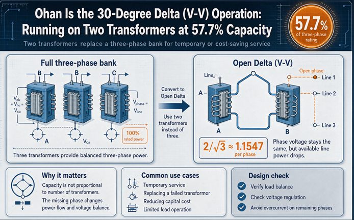
Two 50 kVA transformers wired in open delta deliver 86.6 kVA between them, which is 57.7 percent of the 150 kVA the same three units would deliver closed. The missing 13.4 percent is not a rounding error. It is the price of the 60 degree angle between the two units’ outputs, and it is why the answer is not 66.7 however obvious two thirds looks.
The number itself is not hard to find. Search for open delta and you will get a dozen pages that tell you 57.7 percent, and most of them will also tell you 86.6 percent in the next sentence without explaining how the two numbers relate. That gap is where projects go wrong. A contractor who sizes the service from the two nameplates gets 15 percent more current than the bank can supply. A designer who assumes the two units share load evenly finds one of them at a half power factor and cannot work out why. An electrician who checks the polarity with the closed delta procedure reads 415 volts on a two unit bank that is perfectly correct.
This page works from the geometry outward. Once you have the geometry, every number on this page follows, including the ones that look like typos.
The number is 57.7 percent, and the reason fits in one cosine
Start with the arithmetic everybody agrees on.
Two 50 kVA units in a V carry root three times the rating of one unit. Root three is 1.732, so 86.6 kVA. Three 50 kVA units closed carry three times one unit, so 150 kVA. Divide and you get 0.5774.
That is the whole calculation. What it does not tell you is where 1.732 comes from in a connection that has no wye point and no obvious square root anywhere.
The answer is that the two units’ apparent power outputs are 60 degrees apart. Not 120. Sixty. Each unit delivers 50 kVA, and if you add two 50 kVA vectors that sit 60 degrees apart, you get 86.6, not 100. The vector sum of two equal phasors separated by an angle is twice the cosine of half that angle. Two times cosine of 30 degrees is 1.732.
That single line is the entire derivation, and it explains all the numbers at once:
| What you compare the bank against | Bank capacity | Line current at 240 V | Each unit carries | Verdict |
|---|---|---|---|---|
| Three units’ nameplate, 150 kVA | 150.0 kVA | 360.8 A | 173 percent | 73 percent overload |
| Two units’ nameplate added, 100 kVA | 100.0 kVA | 240.6 A | 116 percent | 15.5 percent overload |
| Root three times one unit, 86.6 kVA | 86.6 kVA | 208.3 A | 100 percent | Correct |
All three rows describe the same two transformers. The percentages differ because the reference differs, and almost every confused conversation about open delta capacity is two people using different rows.
Row one is what happens when a 150 kVA closed bank loses a unit and the plant keeps running. Each of the two survivors now carries 361 amps against a 208 amp winding. That is 73 percent overload, which is a matter of minutes for a distribution transformer with a 65 degree rise. This is why “run it as an open delta until the replacement arrives” is a plan that needs a load shed attached to it.
Row two is what happens when somebody adds 50 plus 50 and gets 100. The bank is loaded to 100 kVA, each unit carries 241 amps, and the overload is 15.5 percent. That will not fail in a minute. It will fail in a year, at the end of a hot summer, and the failure will be blamed on the manufacturer.
Row three is the only one that keeps the windings at nameplate.
Three ways to describe the same bank, three different percentages
The reason this table is worth more than the single number is that the industry quotes five different percentages for this connection, and all five are correct. They are correct in five different frames.
| Percentage | Frame | What it actually says |
|---|---|---|
| 57.7 percent | Against a closed bank of three | How much of the original capacity you kept |
| 66.7 percent | Two of three units, naively | Wrong, and the most common error |
| 86.6 percent | Against the two units installed | How much of your purchase reaches the load |
| 73 percent | Overload if you keep the old load | Why the stopgap has a clock on it |
| 15.5 percent | Overload if you add the nameplates | Why the “100 kVA bank” is not one |
The relationship between the first three is one multiplication. Take 57.7 and divide by 66.7 and you get 0.866. Or take 0.866 and multiply by two thirds, because two units are two thirds of three units, and you get 0.577.
0.866 x (2/3) = 0.577
So 86.6 percent and 57.7 percent are the same fact seen from two directions. One is “what fraction of my metal does useful work.” The other is “what fraction of the old bank did I keep.” Neither is more true. If a supplier quotes you 86.6 percent and a utility engineer quotes you 57.7 percent, they are not disagreeing.
Why 66.7 percent is wrong, and why 86.6 is not a contradiction
Two out of three is 66.7 percent. That is the answer almost everybody gives before they learn otherwise, and it is wrong by 9 percentage points, which on a 150 kVA bank is 13.4 kVA of capacity that does not exist.
The error is a category mistake. Removing one transformer does remove one third of the metal. What it also does is change how the remaining two units relate to each other. In a closed delta, each of the three units carries 57.7 percent of the line current, and the three currents sit 120 degrees apart so that they close on themselves. In an open delta, each of the two units carries the full line current, and their outputs sit 60 degrees apart. The two units are no longer taking turns carrying the load. They are each carrying all of it, at an angle to each other, and the angle is what eats the difference.
Put the two apparent powers on a complex plane. At unity load power factor, one unit sits at plus 30 degrees from the load’s real axis and the other sits at minus 30 degrees. Add them and the imaginary parts cancel while the real parts add to 1.732 times one unit.
| Separation between two equal outputs | Vector sum | In this connection |
|---|---|---|
| 0 degrees | 200 percent | Two identical sources in phase |
| 60 degrees | 173.2 percent | Open delta, the case here |
| 90 degrees | 141.4 percent | Quarter cycle apart |
| 120 degrees | 100 percent | The three line voltages of a balanced set |
| 180 degrees | 0 percent | Exactly opposing |
The 60 degree row is the open delta. The 120 degree row is worth staring at for a moment, because it is what makes the voltage work, and that is the next section.
Where the third phase comes from
Two transformers cannot make three phases. What they can do is make two line-to-line voltages that are 120 degrees apart, and let the load close the triangle. The third voltage is not generated. It is the vector sum of the other two, and it comes out at exactly the right magnitude because of the 120 degree separation.
Take phase A as the reference. The voltage across the first unit runs from A to B. The voltage across the second runs from B to C. Two 240 volt phasors 120 degrees apart.
Add them and the magnitude is 240. Not 415. Not 480. Two times cosine of 60 degrees is 1.0, so two 240 volt phasors 120 degrees apart sum to 240 volts, sitting halfway between them at minus 30 degrees. The load across the open corner A to C sees a correct 240 volt three phase supply.
This is the part that makes open delta useful and the part that makes it confusing, because the same geometry produces both results:
| Quantity | Separation of the two | Cosine factor | Result |
|---|---|---|---|
| Voltage across the open corner | 120 degrees | 2 cos 60 = 1.000 | 240 V, correct |
| Apparent power delivered | 60 degrees | 2 cos 30 = 1.732 | 86.6 kVA, not 100 |
Both rows use the same formula. The angle is different because voltage phasors and apparent power phasors are not the same objects. Voltage across the two units spans 120 degrees. The apparent power each unit delivers sits only 60 degrees from the other, because each unit’s power is measured against its own voltage, and those voltages are already 120 apart.
That is the reason a two unit bank gives you correct voltage and wrong capacity at the same time. There is no fault, no miswiring, and nothing to fix. The voltage is right by construction. The capacity is short by the same construction.
What each transformer actually carries
Here is the sentence that most explanations leave out: in a closed delta, each transformer carries 57.7 percent of the line current. In an open delta, each carries 100 percent of it.
In a closed delta the load current splits three ways through the delta loop, and each winding sees line current divided by root three. In an open delta there is no loop. The two remaining windings are in series with the load around the open corner, so whatever current leaves the bank on a line has to pass through a winding at full value.
The practical consequence is that the same two transformers do more work per amp of line current in the V connection than they did in the delta. They also run hotter for the same load, which is the complaint that brings people to this page in the first place.
| Unit size | Winding amps at 240 V | Open delta bank | Bank line amps | Closed delta bank | Closed line amps |
|---|---|---|---|---|---|
| 25 kVA | 104.2 A | 43.3 kVA | 104.2 A | 75 kVA | 180.4 A |
| 37.5 kVA | 156.3 A | 65.0 kVA | 156.3 A | 112.5 kVA | 270.6 A |
| 50 kVA | 208.3 A | 86.6 kVA | 208.3 A | 150 kVA | 360.8 A |
| 75 kVA | 312.5 A | 129.9 kVA | 312.5 A | 225 kVA | 541.3 A |
| 100 kVA | 416.7 A | 173.2 kVA | 416.7 A | 300 kVA | 721.7 A |
Read the 50 kVA row across. Two of them give 86.6 kVA and 208 amps. The same two plus a third give 150 kVA and 361 amps. The bank line current in the open delta is exactly the winding current of one unit, which is a useful check on any calculation: if your line current exceeds the winding rating of the smaller unit, the bank is not rated for it.
Translated into service hardware: two 50 kVA units support a 200 amp service. Three support a 400 amp service. That is the whole upgrade, and it is why the third transformer is worth more than its nameplate suggests.
The power factor each unit runs at, and the one that reads leading
This is the part of open delta behavior that generates the most service calls, and it is not in most of the published explanations.
Because the two units sit at plus 30 and minus 30 degrees from the load’s real axis, each one runs at a power factor of cosine 30 plus or minus the load’s own angle. At unity load power factor both units run at 0.866. At a load power factor of 0.866, one unit runs at unity and the other at 0.5.
| Load power factor | Unit A angle | Unit A power factor | Unit B angle | Unit B power factor | Unit A real power | Unit B real power |
|---|---|---|---|---|---|---|
| 1.000 | 30.0 lagging | 0.866 | 30.0 leading | 0.866 | 86.6 percent | 86.6 percent |
| 0.950 | 48.2 lagging | 0.667 | 11.8 leading | 0.979 | 66.7 percent | 97.9 percent |
| 0.900 | 55.8 lagging | 0.561 | 4.2 leading | 0.997 | 56.1 percent | 99.7 percent |
| 0.866 | 60.0 lagging | 0.500 | 0.0 | 1.000 | 50.0 percent | 100.0 percent |
| 0.800 | 66.9 lagging | 0.393 | 6.9 lagging | 0.993 | 39.3 percent | 99.3 percent |
| 0.700 | 75.6 lagging | 0.249 | 15.6 lagging | 0.963 | 24.9 percent | 96.3 percent |
Two things fall out of that table.
The first is that at unity load power factor, one unit reads 0.866 lagging and the other reads 0.866 leading. A leading power factor on a transformer that is supplying a lagging plant looks like a miswired current transformer, or a reversed polarity, or a meter problem. It is none of those. It is the geometry. The unit on the leading side is absorbing reactive power rather than delivering it, and it does that because the other unit is delivering more reactive than the load needs. The excess circulates between them.
The second is that the units do not share real power evenly, and the split gets worse as the load power factor falls. At 0.8 load power factor, which is an ordinary motor load, one unit delivers 39 percent of its rating in watts while the other delivers 99 percent. Both carry the same current. Both run at the same temperature. One of them is doing a third of the useful work.
That last point corrects a claim you will find on several pages about this connection. They say the two transformers are loaded unevenly and imply that one gets hot. At balanced three phase load in an open delta, the two winding currents are identical in magnitude, so the two units run at the same temperature. What is uneven is the real power, not the current. If you put a kWh meter on each unit you will see a ratio near two and a half to one at 0.8 power factor, and if you try to work out loading from those kWh readings you will conclude the bank is badly unbalanced when it is perfectly fine.
Hanging single phase load on a two transformer bank
An open delta has three conductors and no neutral, so there is no line to neutral load to hang. The moment you center tap one unit you get a neutral, and then the placement of the single phase load starts to matter by a factor of two.
There are three pairs of conductors. Two of them have a transformer across them. The third, the open corner, does not. A single phase load across a pair with a transformer is carried by that transformer alone, at unity power factor, and 10 kVA of load uses 10 kVA of capacity.
A single phase load across the open corner is different. The current has to go through both units in series, and each unit sees that current at 60 degrees to its own voltage. The result is that each unit carries the full 10 kVA of apparent power while the load only receives 10 kVA of real power. You installed 100 kVA and you are using 20 kVA of it to deliver 10.
| Load placement | Units in the path | Apparent power in each | Total capacity used | Power factor of each unit |
|---|---|---|---|---|
| Across a pair with a transformer | 1 | 10 kVA | 10 kVA | 1.00 |
| Across the open corner | 2 in series | 10 kVA | 20 kVA | 0.50 each |
The rule that follows is short. On a center tapped open delta, hang every 120 volt and every single phase 240 volt load on the center tapped unit, and never across the open corner. The open corner is the pair with no transformer on it, which on a typical pole bank is the pair the utility left empty. It is the one pair where a single phase load doubles its own cost.
The fault current is two numbers, not one
Because the open corner puts two windings in series, a fault across it sees twice the impedance that a fault across a transformer pair sees. The available fault current is not one number for the bank. It is two, and the ratio is exactly two to one.
Work it through for two 50 kVA units at 240 volts with 1.5 percent impedance. The winding impedance in ohms is the voltage squared over the kVA, times the per unit value.
    240 x 240 / 50,000 = 1.152 ohms base
    1.152 x 0.015 = 0.01728 ohms per unit
A line to line fault across a pair with a transformer on it sees 0.01728 ohms, so 240 divided by 0.01728 is 13,889 amps. A line to line fault across the open corner sees both windings in series, 0.03456 ohms, so 6,944 amps.
| Impedance per unit | Ohms per winding | Fault across a transformer pair | Fault across the open corner | Ratio |
|---|---|---|---|---|
| 1.5 percent | 0.01728 | 13,889 A | 6,944 A | 2.00 |
| 2.0 percent | 0.02304 | 10,417 A | 5,208 A | 2.00 |
| 2.5 percent | 0.02880 | 8,333 A | 4,167 A | 2.00 |
Two consequences, and they pull in opposite directions.
For equipment rating, the higher number governs. A breaker or a switchboard on this bank has to interrupt 13.9 kA if the fault lands on the wrong pair, even though the open corner would only deliver 6.9 kA. Sizing from the open corner number is how a panel ends up with a 10 kA rating on a bank that can put out 14.
For protection speed, the lower number is the problem. A breaker with a 10 kA interrupting rating is fine at the open corner and not fine at the other two pairs. And an instantaneous trip unit set from the higher value may not pick up a low level arcing fault at the open corner at all, because that fault has half the current to work with. This is the same shape of problem as a high impedance unit that cannot clear a bolted fault, and it is worth checking on any bank where the two units are not identical, because unequal impedances make the split worse.
Voltage regulation and motor starting on a softer source
The doubled impedance at the open corner is not only a fault current issue. It is a running voltage issue, and it shows up every time a motor starts.
Take the same bank at 1.5 percent per unit on each winding. At three times the bank’s rated current, which is a moderate motor start, the pair with a transformer on it drops 4.5 percent. The open corner drops 9 percent, because both windings are in the circuit and both are at three times rated current.
| Starting current, multiple of bank rating | Drop across a transformer pair | Drop across the open corner |
|---|---|---|
| 2 times | 3.0 percent | 6.0 percent |
| 3 times | 4.5 percent | 9.0 percent |
| 6 times | 9.0 percent | 18.0 percent |
An 18 percent dip on a 240 volt system puts the motor terminal at 197 volts during the start. NEMA MG-1 allows a running motor to operate at plus or minus 10 percent of nameplate, and a start is not steady state, so the motor will usually still accelerate. What it will not do is accelerate quickly. Starting torque falls with the square of the voltage, so an 18 percent dip costs about a third of the starting torque, and a loaded conveyor or a positive displacement pump that was marginal on a closed bank will stall on an open one.
This is why open delta is a poor fit for the largest motor on the site even when the running kVA fits comfortably. Size the bank for the starting current, not the running current, or accept that the biggest motor needs a soft start.
Losses move in opposite directions
There is an economic argument for two transformers that rarely gets made with numbers, and it runs both ways depending on load.
No load loss scales with the number of units, so two units lose a third less than three at idle. Load loss scales with the square of the current in each winding, and in an open delta each winding carries the full line current instead of 57.7 percent of it, so the copper loss goes the other way.
Take a 150 kVA closed bank of three 50 kVA units, and compare it with two of the same units in open delta, at the same delivered load. Use 200 watts of no load loss and 700 watts of load loss per unit, which is typical for a 50 kVA distribution transformer and is an assumption, not a specification.
| Load delivered | Closed bank, three units | Open bank, two units | Difference |
|---|---|---|---|
| 20 kVA | 637 W | 475 W | 162 W less |
| 40 kVA | 749 W | 699 W | 50 W less |
| 46 kVA | 800 W | 800 W | Even |
| 60 kVA | 936 W | 1,072 W | 136 W more |
| 86.6 kVA | 1,300 W | 1,800 W | 500 W more |
The crossover on those assumptions is around 46 kVA, which is 31 percent of the closed bank’s rating and 53 percent of the open bank’s. Below that, two transformers burn less because the no load loss you avoided is bigger than the copper loss you added. Above it, the copper loss dominates and the two unit bank is the more expensive one to run, by 500 watts at full output.
Five hundred watts continuous is 4,380 kWh a year. At ten cents that is about 440 dollars, which is not a reason to choose a connection, but it is a reason not to describe open delta as the cheap option without qualification. It is cheaper to buy and more expensive to run at load.
The copper loss comparison is worth stating exactly, because the ratio is clean. At full open delta output each winding is at 100 percent, so copper loss is two times one squared. At the same 86.6 kVA the closed bank has each unit at 57.7 percent, so copper loss is three times 0.577 squared, which is one. Two against one. The open delta burns exactly twice the copper loss to deliver the same load, and saves one unit’s worth of no load loss, and the two effects land at about 46 kVA on a 50 kVA unit size.
Closing the delta later, and the current that appears first
Every description of open delta mentions that you can add the third unit later. Almost none of them mention what the third unit has to match, and the distinction matters because two different mismatches have two different consequences.
A ratio mismatch produces circulating current. If the third unit’s turns ratio is off by one percent from the other two, the difference appears as a voltage around the closed delta loop, and current flows through all three windings before any load is connected. The magnitude is the mismatch divided by the sum of the per unit impedances.
0.01 / (0.015 + 0.015) = 0.333 per unit
One percent of ratio error, with 1.5 percent impedance on each unit, circulates 33 percent of rated current with the bank sitting at no load. Half a percent gives 17 percent. Two percent gives 67 percent, which will cook the bank in a week.
An impedance mismatch does not circulate current. It makes the units share load unequally, which shows up as voltage unbalance under load rather than as current at idle. Two units at 1.5 percent and one at 2.5 percent will run at noticeably different temperatures at full load, and the one with the lower impedance carries more.
| Mismatch | What it produces | Symptom at no load | Symptom at load |
|---|---|---|---|
| Turns ratio differs | Circulating current around the loop | Current with no load connected | Extra heat everywhere, worse with mismatch |
| Impedance differs | Unequal current sharing | Nothing | One unit hotter, voltage unbalance |
| Both differ | Both of the above | Current, and it is hard to explain | The worst of both |
Before you close any delta, run the open corner test. Wire the three units into the delta but leave one corner open. Energize. Measure across the open corner. It reads zero if the polarities are right, and it reads twice the phase voltage if one unit is reversed, so 480 volts on a 240 volt system.
On a two unit open delta the same test has a different signature, and this is the detail that gets missed. With only two units, a reversed winding makes the open corner read root three times the phase voltage, which is 415.7 volts on a 240 volt system, not 480.
| Bank | Correct reading across the open point | One unit reversed |
|---|---|---|
| Two units, open delta | 240 V, the correct line voltage | 415.7 V |
| Three units, closed delta | 0 V | 480 V |
Two different numbers for two different mistakes. An electrician who expects 480 on a two unit bank, reads 415, and concludes the bank is fine has just energized a reversed winding, and the motor on the far end will run backwards or draw twice its rated current, depending on which way the load is connected.
The center tapped open delta
The most common open delta in North America is not a stopgap. It is a permanent service on a pole, feeding a farm or a small shop, with one center tapped unit and one plain unit. The center tap gives 120 volt legs for lighting and receptacles. The two units together give 240 volt three phase for a pump or a compressor.
The capacity rule for this bank is not the rule people expect. The bank is limited by the smaller unit, not by the sum.
    43.3 kVA = 1.732 x 25 kVA, from a 25 plus 25 pair
    43.3 kVA = 1.732 x 25 kVA, from a 25 plus 50 pair
    43.3 kVA = 1.732 x 25 kVA, from a 25 plus 75 pair
All three of those banks are 43.3 kVA. The bigger unit buys you headroom on one side and nothing on the other. This is why a utility pole bank often looks like one small can and one large can: the small one is the lighting unit with the center tap, and it sets the bank capacity, while the large one is the power unit and runs at half load.
| Pairing | Bank three phase capacity | Small unit loading | Large unit loading |
|---|---|---|---|
| 25 plus 25 | 43.3 kVA | 100 percent | 100 percent |
| 25 plus 37.5 | 43.3 kVA | 100 percent | 67 percent |
| 25 plus 50 | 43.3 kVA | 100 percent | 50 percent |
Now the part that costs people money. The 120 volt load and the three phase load share the center tapped unit, and they share it in kVA. A center tapped 25 kVA unit has 12.5 kVA available on each 120 volt leg, or 25 kVA across both legs if the load is balanced, and it has 25 kVA total to divide between lighting and its share of the three phase load.
Subtract the lighting and the bank shrinks by root three times the subtraction:
| 120 volt load on the center tapped unit | Capacity left for three phase | Bank capacity |
|---|---|---|
| 0 kVA | 25.0 kVA | 43.3 kVA |
| 5 kVA | 20.0 kVA | 34.6 kVA |
| 10 kVA | 15.0 kVA | 26.0 kVA |
| 15 kVA | 10.0 kVA | 17.3 kVA |
| 20 kVA | 5.0 kVA | 8.7 kVA |
Ten kVA of lighting on a 25 kVA center tapped unit costs 17 kVA of three phase capacity. That is the number to have in your head when a customer wants to add a building full of receptacles to a farm service that already runs a pump. The pump does not get slower gradually. At some point the bank capacity drops below the motor’s running kVA and the unit that fails is the one with the center tap, which is also the one that feeds the house.
The subtraction is conservative because it treats the two loads as adding in kVA rather than as vectors. In practice, if the 120 volt load is resistive and the three phase load is at 0.85 power factor, the currents do not add arithmetically and you get some capacity back. Treating it as a straight subtraction is the safe direction for a sizing decision.
Two potential transformers, and what they cannot see
Open delta is not only a power connection. Two potential transformers wired in open delta are a standard way to give a meter or a relay three phase voltage while buying two transformers instead of three, and the saving is real.
The connection works because a three wire circuit has three line to line voltages and only two of them are independent. Measure A to B and B to C, and A to C follows from Kirchhoff. Blondel’s theorem says exactly this: a three wire system needs two wattmeters, and by the same logic two potential transformers are enough to meter it correctly.
What two potential transformers cannot do is see zero sequence. Every line to line voltage is free of zero sequence by definition, since zero sequence appears equally on all three phases and cancels in any line to line difference. So a relay fed from an open delta PT set has no way to measure neutral displacement, no matter how it is programmed.
| What you want to measure | Two PTs in open delta | Three PTs in broken delta |
|---|---|---|
| Three phase line voltages | Yes | Yes |
| Three phase power, three wire | Yes | Yes |
| Zero sequence voltage | No, structurally impossible | Yes |
| Ground fault on an ungrounded system | No | Yes |
| Neutral displacement on a resistance grounded system | No | Yes |
The consequence is specific. If the system is ungrounded, or high resistance grounded, the ground detector depends on measuring neutral displacement, and an open delta PT set cannot supply that measurement. A design that uses two PTs for metering and expects the same two to feed a 59N element will have a relay that never operates, and the failure will look like a setting problem, not a wiring problem, because the wiring is correct for what it does.
This is the same theme that runs through system grounding generally. The sensor you install decides what you are able to detect, and no amount of relay logic recovers a quantity the sensor never measured.
Sizing backwards, and the 15.5 percent signature
Design goes the other direction from analysis. You have a load, and you need unit sizes.
The rule is one line. Each unit has to be at least the load divided by root three.
60 kVA load / 1.732 = 34.6 kVA, so two 37.5 kVA units
Two 37.5 kVA units give 65 kVA, which covers 60 with a little room. The same 60 kVA on a closed bank needs three 20 kVA units, which is not a standard size, so three 25 kVA units at 75 kVA.
| Load | Minimum unit | Standard unit | Open bank installed | Open bank delivered | Same load, closed bank |
|---|---|---|---|---|---|
| 30 kVA | 17.3 kVA | 25 kVA | 50 kVA | 43.3 kVA | 3 x 15 = 45 kVA |
| 60 kVA | 34.6 kVA | 37.5 kVA | 75 kVA | 65.0 kVA | 3 x 25 = 75 kVA |
| 86.6 kVA | 50.0 kVA | 50 kVA | 100 kVA | 86.6 kVA | 3 x 37.5 = 112.5 kVA |
| 130 kVA | 75.0 kVA | 75 kVA | 150 kVA | 129.9 kVA | 3 x 50 = 150 kVA |
Look at the 60 kVA row. Seventy five kVA installed either way. Closed gives you 75 kVA of capacity. Open gives you 65. For the same metal you lose 13.4 percent, which is the same 13.4 percent from the top of this page, now showing up as a purchasing decision rather than a physics one.
The 86.6 kVA row is where open delta starts to win, because 50 kVA is a standard single phase size and 37.5 is often not stocked. Two 50s cost less than three 37.5s in most yards, and the capacity is nearly identical.
Now the signature error, which is the one to watch for in someone else’s calculation. Add the two nameplates, divide by root three times the voltage, and you get a line current that is 15.5 percent too high. On two 50 kVA units at 240 volts:
    Wrong: 100,000 / (1.732 x 240) = 240.6 A
    Right:  86,600 / (1.732 x 240) = 208.3 A
Fifteen and a half percent is the signature. It is the reciprocal of 0.866, so it is the same error as the 13.4 percent capacity shortfall, expressed as an oversize instead of a shortfall. If a proposal shows a line current that is 15 percent above what root three times one unit would give, the designer added the nameplates first. The feeder, the breaker and the service will all be sized from that number, and the bank will be asked to carry a load it cannot.
The code treats each unit as its own transformer
There is no such thing as an open delta bank in the electrical code. There are two transformers, each with its own nameplate, its own primary protection and its own grounding question, and that framing settles most of the code issues before they start.
Overcurrent protection follows the per unit rule. Each transformer is protected at up to 125 percent of its own primary current, or the next standard size up, under the transformer protection table in NEC 450.3(B). There is no bank level allowance and no credit for the fact that the two units share a load. A 50 kVA unit at 240 volts carries 208 amps, so its primary protection is sized from its own primary current, and the fact that the other unit exists does not change the calculation.
Grounding follows the conductor count. A three wire delta has no neutral, so there is nothing to bond at the source, and these banks are commonly run ungrounded. That is a choice with a consequence, which is the ground detector requirement for systems that are not grounded in NEC 250.21. If the bank is center tapped, the midpoint of that one winding becomes the grounded conductor under 250.26 and the system becomes a four wire delta, with the high leg marking requirement in 110.15 that goes with it.
Ground fault protection for services does not reach these banks. The service ground fault rule in 230.95 applies to solidly grounded wye services above a threshold, and a 240 volt three wire delta is not one. Do not assume a ground fault relay is protecting the service just because the service is large.
One more that catches people on the primary side. Only two of the three primary lines land on a winding, and the third carries the vector sum of the other two. Each unit’s primary protection is sized from that unit’s own primary current, which is the secondary winding current divided by the turns ratio, and there is no separate bank allowance for it. The two to one fault current split appears on the primary side as well, because a primary fault across the open corner puts both primary windings in series, so a device at the open corner sees half the current it sees for a fault across a single unit. Check both locations before you accept a coordination study, and check the primary current per winding rather than the bank kVA divided by root three times primary voltage.
When two transformers is the right answer
Open delta is a good engineering choice in a narrow set of conditions, and a bad one just outside them.
It is the right answer when the three phase load is small relative to the single phase load, which is the farm and rural shop case. It is the right answer when the load is temporary, because two units move twice as easily as three and the third one is often not available. It is the right answer when one unit of an existing bank has failed and the plant needs three phase power for a week while a replacement ships, provided the load is shed to fit. It is the right answer when the physical space will not take a three unit bank or a single three phase unit. It is the right answer for instrument transformers, where two potential transformers do everything a meter needs.
It is the wrong answer when a single motor dominates the load, because the voltage dip at the open corner is twice the dip across a pair and starting torque falls with the square of voltage. It is the wrong answer when the three phase load is within 20 percent of the bank capacity, because there is no margin for the imbalance that real loads produce. It is the wrong answer when the site has significant harmonic producing load, because the closed delta is what gives triplen harmonic currents a path to circulate, and the open corner breaks that path so the harmonic current goes into the supply instead. It is the wrong answer when someone is planning to grow into the capacity, because the third unit is not a simple addition if the first two were sized for the V connection and the new unit has to match both ratio and impedance.
The last one deserves a sentence. Adding the third unit to an open delta that was built as an open delta works, and it is the cheapest capacity you will ever buy, provided the new unit matches. Adding it to a bank where the two existing units were already mismatched, or where one is a rebuilt unit with a different impedance, produces circulating current from the moment you close the loop, and the symptom is a bank that runs hot at no load.
FAQ
Why is an open delta 57.7 percent and not 66.7 percent?
Because removing one transformer does not just remove one third of the metal. In a closed delta each unit carries 57.7 percent of the line current. In an open delta each carries all of it, and the two units’ apparent power outputs sit 60 degrees apart. Two equal outputs 60 degrees apart add to 1.732 times one unit, not 2. So the bank delivers 1.732 units instead of 3, which is 57.7 percent.
What is the capacity of two 50 kVA transformers in open delta?
86.6 kVA at any voltage, which is 1.732 times 50. At 240 volts that is 208 amps of line current. At 480 volts it is 104 amps. Each unit carries its full rated current, so the bank cannot deliver more than one unit’s winding current on any line, no matter how the load is balanced.
Does an open delta still give 240 volts three phase?
Yes. Two 240 volt windings 120 degrees apart sum to 240 volts because twice the cosine of 60 degrees is 1.0. The load across the open corner sees a correct balanced three phase voltage. What it does not get is the current behind that voltage that a third transformer would provide.
Can you run an open delta permanently?
Yes, and utilities do it on rural services for decades. The conditions are a three phase load that stays well under the bank rating, a single phase load that fits on the center tapped unit, and no single motor large enough that its starting current drags the open corner down. The bank is a permanent installation, not an emergency measure, when it is sized for those conditions.
How much current circulates if I close the delta with a mismatched unit?
One percent of turns ratio error with 1.5 percent impedance on each unit circulates 33 percent of rated current at no load. Half a percent gives 17 percent. Two percent gives 67 percent. The current is almost entirely reactive, so a wattmeter shows nothing while the windings cook.
How do I test polarity before closing a delta?
Wire the bank with one corner open, energize, and measure across the open corner. On a three unit closed delta the correct reading is zero volts and a reversed unit reads twice the phase voltage, so 480 volts on a 240 volt system. On a two unit open delta the correct reading is the normal line voltage and a reversed unit reads 1.732 times it, so 415.7 volts on a 240 volt system. The two connections have different signatures.
Can an open delta supply 120 volt loads?
Only if one unit is center tapped, and then the 120 volt load competes with the three phase load for that unit’s capacity in kVA. On a 25 kVA center tapped unit, 10 kVA of lighting leaves 15 kVA for three phase duty, which makes the bank 26 kVA instead of 43.3. Hang the 120 volt load on the center tapped unit and never across the open corner.
What is the fault current of an open delta bank?
Two values, differing by a factor of two. A fault across a pair with a transformer on it sees one winding impedance. A fault across the open corner sees both windings in series, so it sees twice the impedance and delivers half the current. On two 50 kVA units at 240 volts with 1.5 percent impedance that is 13,889 amps and 6,944 amps.
Why do the two transformers run at different power factors?
Because each unit’s output sits 30 degrees from the load’s real axis, one on each side. At unity load power factor both units run at 0.866, one lagging and one leading. At 0.866 load power factor one unit runs at unity and the other at 0.5. The leading unit is absorbing reactive power that the other unit is over-producing, and the excess circulates between them.
Can I add a third transformer later to an open delta?
Yes, and it is the cheapest capacity available, if the new unit matches the existing two on both turns ratio and impedance. A ratio mismatch circulates current around the closed loop immediately, 33 percent of rated for one percent of error. An impedance mismatch does not circulate but makes the units share load unequally. Check both before you close the corner.
What size breaker protects an open delta bank?
Each unit is protected on its own nameplate, at up to 125 percent of its own primary current or the next standard size up. There is no bank level allowance, and the fact that the two units share a load does not change any individual unit’s protection. Size the primary protection from the primary current of the unit it protects, and check the primary current per phase.
Is an open delta the same as a V-V connection?
Yes. V-V, open delta, and open-delta-open-delta all describe the same two transformer connection. The V refers to the shape of the two windings when drawn against the three lines. Open-wye open-delta is different: it has one unit connected phase to neutral on the primary side and is used on utility primaries where two line-to-neutral cutouts are cheaper than three line-to-line ones.