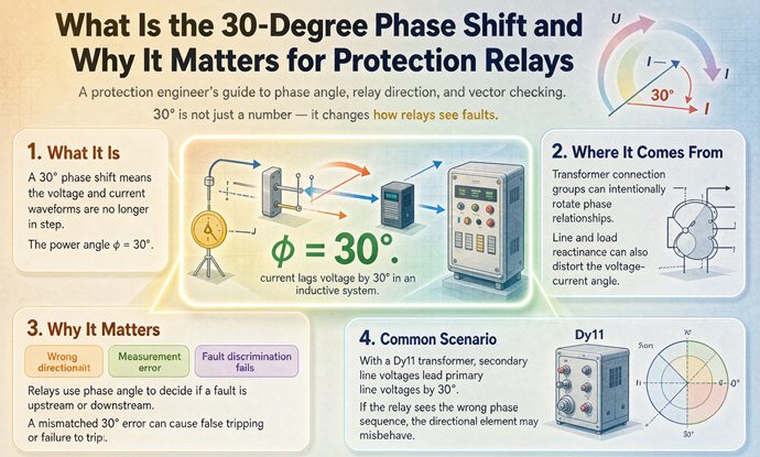
The 30-degree shift is the angle between a delta winding and a wye winding. It is geometry, not a fault: a delta winding spans two lines, so its voltage is the difference of two phases 120 degrees apart, 1.732 times larger and 30 degrees out. Uncompensated, an 87T relay reads 51.8 percent of load current as differential and trips at 58 percent load.
That is the whole answer in two sentences, and it is worth sitting with for a moment, because it explains a phone call that comes in roughly once a month from a plant that just energized a perfectly good transformer and watched the main breaker open on the first close of the day. Nothing was wrong with the transformer. Nothing was wrong with the relay. The relay was doing exactly what it was told to do, on currents it had every right to believe were 30 degrees apart, and the arithmetic said fault.
The short version, in seven numbers
If you only read one table on this page, read this one.
| Question | Number | Why it is that number |
|---|---|---|
| Phase shift from delta to wye | 30 degrees, always | Line-to-line voltage is the vector difference of two phase voltages |
| Shift of a standard North American delta-wye unit | 30 degrees, LV lagging | IEEE C57.12.00, clock hour 1 |
| Shift of a standard IEC delta-wye unit | 30 degrees, LV leading | IEC 60076-1, clock hour 11 |
| Difference between those two units | 60 degrees | Two clock hours apart, not zero |
| Angle a differential relay sees with no compensation | 150 degrees | 30 degrees of shift plus the 180 degree reversal at the terminals |
| False differential at full load, no compensation | 51.8 percent | Two equal phasors 150 degrees apart sum to 0.518 |
| Load at which a 0.30 pu differential element trips | 58 percent | 0.518 times load reaches 0.30 at 0.58 |
Seven rows, and four of them are numbers most people working on this equipment have never seen written down. The rest of this page is the derivation of each one, and what to do about it.
Where the 30 degrees actually comes from
Most explanations of this start with the winding connection and stop there. “A delta-wye transformer shifts by 30 degrees because of the connection.” That is true and it is useless, because it does not tell you why 30 and not 45, and it does not tell you why you cannot buy a 15 degree unit.
Start instead with a single number. Take a 480Y/277 volt system. The phase-to-neutral voltage is 277 volts. Phase A sits at 277 volts at zero degrees. Phase B sits at 277 volts at minus 120 degrees. Those two phasors are 120 degrees apart, which is what a three-phase system is.
Now measure from phase A to phase B, because that is what a delta winding does. It has no neutral, so it can only be connected across two lines. The voltage across it is the vector difference:
277 at 0 degrees, minus 277 at minus 120 degreesDraw the triangle. Two sides of 277 with 120 degrees between them. The third side is 277 times 1.732, which is 480. And the angle of that third side, measured from phase A, is plus 30 degrees.
That is the whole mechanism. A delta winding connected across lines A and B carries a voltage that is 1.732 times the phase voltage and rotated 30 degrees from it. A wye winding on the same core carries the phase voltage with no rotation. Put one on each side and the secondary is 30 degrees away from the primary, on every cycle, forever, with no way to tune it out.
Three consequences fall straight out of that triangle.
The shift is exactly 30 degrees, not approximately. There is no tolerance on it. The winding either spans two lines or it does not.
The magnitude ratio and the angle come as a package. The same geometry that gives you 1.732 also gives you 30 degrees. That is why the compensation matrix downstream, in a numerical relay, has a 1 divided by 1.732 factor sitting in it next to the phase rotation. The relay is undoing both halves of the same triangle.
Only multiples of 30 degrees are available. The phasors in a three-phase system sit 30 degrees apart once you count both line and phase quantities, and any of them can be inverted by reversing a lead, so the reachable positions are the twelve clock hours and nothing between them. This is the part that surprises buyers who ask for a 15 degree unit. It does not exist as a stock item, and it does not exist as a custom item without a separate regulating winding doing the phase shifting.
The clock face is just this triangle, numbered
IEC 60076-1 writes the answer as a clock hour. With the high voltage phasor held at 12 o’clock, the low voltage phasor points at the hour given by the number, and each hour is 30 degrees of lag.
| Vector group | Clock hour | Low voltage relative to high voltage | Where you meet it |
|---|---|---|---|
| Dyn1 | 1 | lags by 30 degrees | North American distribution per IEEE C57.12.00 |
| Dyn11 | 11 | leads by 30 degrees | IEC and most export projects |
| Dyn5 | 5 | lags by 150 degrees | Legacy plants, older utility practice |
| Dyn7 | 7 | leads by 150 degrees | Legacy plants, older utility practice |
| YNd1 | 1 | lags by 30 degrees | Generator step-up, grounded high side |
| Dd0 | 0 | in phase | Industrial delta systems, no neutral |
| Yyn0 | 0 | in phase | Small four-wire distribution |
Note what the delta-wye column can and cannot do. All four odd hours are reachable, and no even hour is. A wye-wye or delta-delta unit can only land on an even hour, and in practice on 0 or 180, because two windings of the same shape produce phasor sets that can only be displaced by multiples of 60. The 30 degree step exists only when you pair a delta with a wye, and that is a direct consequence of the triangle above, not a convention somebody chose.
IEEE says lag, IEC says lead, and those two are 60 degrees apart
This is where most of the confusion on the internet lives, and it is worth untangling carefully because it costs real money.
IEEE C57.12.00 fixes the displacement for standard North American units in words rather than clock hours. For wye-delta and delta-wye connections, the angular displacement between the high voltage and low voltage phase voltages is 30 degrees, with the low voltage lagging the high voltage. In clock terms, that is hour 1. A standard American delta-wye distribution transformer is a Dyn1.
IEC 60076-1 uses the clock notation without picking a favourite. European practice settled on hour 11, where the low voltage leads by 30 degrees.
Both units have a 30 degree shift. Both are correct. Both are common. And they are 60 degrees apart from each other, because 11 o’clock and 1 o’clock are two hours apart, and two hours is 60 degrees, not zero.
This is the single most expensive misunderstanding in the subject. A buyer writes “delta-wye, 13.8 kV to 480Y/277” on an enquiry, gets a Dyn11 because that is what the factory builds for export, and installs it next to an existing Dyn1. On paper the two units match on every line except one. Same kVA, same ratio, same impedance within half a point, same winding arrangement. They cannot be paralleled, and they cannot be tied through a bus tie, and the reason is one digit.
If you take one action item from this page, make it this one: write the clock hour on the enquiry. “Delta-wye” is a winding arrangement. It is not a specification. Dyn1 and Dyn11 are different products.
The direction does not change the differential, but it changes the correction
Here is a detail that trips up even experienced people. Getting the direction wrong does not change the 51.8 percent number, because the magnitude of the sum of two equal phasors depends only on how far apart they are. Plus 30 or minus 30, the answer is the same 0.518.
What the direction changes is the compensation. The correction has to be applied in the opposite direction to the shift, and if you apply it in the same direction, you do not cancel 30 degrees, you add 30 more. That is the failure mode described in the next section, and it is why the direction matters even though the standing differential looks identical either way.
What the relay actually sees is 150 degrees, not 30
Every popular explanation says the relay sees a 30 degree mismatch. That is the physics, and it is not what the terminals carry. The number at the relay is 150 degrees, and if you do not know why, you will not be able to reconcile the meter reading with the theory.
The reason is the polarity convention. A differential relay protects a zone, and every CT feeding it is wired with its polarity mark pointing into that zone. Under load, current enters the zone at the high voltage bushings and leaves at the low voltage bushings. Both CTs see current flowing toward the transformer, so the current the low side CT delivers to the relay is the negative of the current actually leaving.
Take the high side current as 1 per unit at zero degrees. The low side current, with the transformer shift, is 1 per unit at minus 30. The CT reverses it, so the relay input is 1 per unit at 150 degrees. The two inputs are 150 degrees apart, and their sum has a magnitude of 0.518 per unit.
magnitude of (1 at 0 degrees plus 1 at 150 degrees)
  = 2 times cosine of 75 degrees
  = 0.518
That is the number. Not 30, not 51.8 percent by coincidence, but 51.8 percent because 150 degrees is 75 degrees either side of a half turn, and the cosine of 75 is 0.259, doubled.
This also resolves the apparent contradiction between the sources. The transformer shift is 30 degrees. The relay terminals show 150. Both statements are true, and the difference is a 180 degree reversal that nobody mentions because it is buried in how the CTs are pointed.
How much differential each angle buys you
The relationship is not linear, and its shape matters.
| Separation at the relay terminals | False differential, equal currents | What produces it |
|---|---|---|
| 180 degrees | 0 percent | Correct compensation |
| 175 degrees | 8.7 percent | A 5 degree CT or relay angle error |
| 170 degrees | 17.4 percent | A 10 degree error |
| 165 degrees | 26.1 percent | A 15 degree error |
| 150 degrees | 51.8 percent | No compensation, Dyn1 or Dyn11 |
| 120 degrees | 100.0 percent | Compensation applied backwards |
| 90 degrees | 141.4 percent | Two independent errors compounding |
The function is steepest at balance and flattens as the angle grows. Around 180 degrees, one degree of error produces about 1.74 percent of differential. That sounds small until you remember that CT phase error, relay measurement error, and residual mismatch after ratio correction all live in the one to three degree range. A perfectly wired, perfectly compensated scheme still carries two to five percent standing differential, which is why differential elements have a minimum pickup instead of being set to zero.
| Angle error | False differential |
|---|---|
| 1 degree | 1.74 percent |
| 2 degrees | 3.49 percent |
| 3 degrees | 5.23 percent |
| 5 degrees | 8.72 percent |
| 10 degrees | 17.4 percent |
| 15 degrees | 26.1 percent |
| 30 degrees | 51.8 percent |
Read the top of that table again. Three degrees of error is already 5.2 percent of rated current showing up as differential. That is not a wiring mistake. That is the normal cost of doing business, and it is the reason the pickup setting exists.
The arithmetic on a 1,000 kVA unit
Numbers make this concrete. Take a 1,000 kVA, 13.8 kV to 480Y/277 volt unit at 5.75 percent impedance, sitting on a plant bus.
At 480 volts the secondary full-load current is 1,202.8 amps. At 13.8 kV the primary full-load current is 41.8 amps. Those are the two currents the relay is comparing, after the CT ratios bring them down to a common base.
With no phase compensation, the standing differential at full load is 0.518 times the load current:
| Quantity | On the 480 V side | On the 13.8 kV side |
|---|---|---|
| Full-load current | 1,202.8 A | 41.8 A |
| False differential at 100 percent load | 622.6 A | 21.6 A |
| False differential at 50 percent load | 311.3 A | 10.8 A |
| Typical minimum pickup, 0.30 pu | 360.8 A | 12.6 A |
| Load at which the element operates | 58 percent | 58 percent |
Read the last row. The element operates at 58 percent of rated load. Not at a fault. At 58 percent load, which is a Tuesday morning.
And 0.30 per unit is a conservative setting. Unit transformers and generator step-up units are often set nearer 0.125 per unit to catch turn-to-turn faults early. At 0.125, the same uncompensated scheme operates at 24 percent of rated load. The transformer trips before the plant reaches a quarter of its capacity.
Sit with what the relay is being asked to do. It sees 622.6 amps of differential on a unit rated 1,202.8. An internal fault in the first few percent of a winding, the kind this element exists to catch, produces less than that. The relay has no way to tell a healthy unit at full load from a genuinely faulted one, because the signal it is looking at is larger than most real faults it will ever see.
The per-unit nature of the error is worth noting too. On the 13.8 kV side the false differential is 21.6 amps, which looks like nothing. Put it through a 50/5 CT and it is 2.16 amps at the relay terminals, which is enormous. Per-unit errors do not get smaller on the high side. They get smaller in amperes and stay identical in per unit, because that is what a per-unit system is for.
The correction, and the mistake that doubles the error
There are two ways to fix this, one old and one new, and each has a failure mode that produces a bigger error than doing nothing.
Delta connected CTs, and the DAB versus DAC question
The electromechanical and static answer is to wire the CTs on the wye side in delta. A delta CT bank adds 30 degrees, so you point it backwards and it cancels the transformer’s 30. It also, as a free side effect, blocks zero sequence, which is covered further down.
The trap is that there are two ways to build that delta, and they rotate in opposite directions. Connect the CT secondaries as A minus B and you get one direction. Connect them as A minus C and you get the other. One is called DAB in the literature, the other DAC, and only one of them is the mirror image of the power transformer’s own delta.
Pick the wrong one and the compensation adds 30 degrees in the wrong direction instead of subtracting it. The total separation at the relay goes from 150 degrees to 120 degrees, the false differential goes from 51.8 percent to 100 percent, and the transformer now trips at 30 percent of load instead of 58.
| Compensation | Separation at relay | False differential | Trips at |
|---|---|---|---|
| None, wye CTs both sides | 150 degrees | 51.8 percent | 58 percent load |
| Correct delta CTs, mirror image | 180 degrees | 0 percent, plus normal error | Never, on load alone |
| Wrong delta CTs, add instead of subtract | 120 degrees | 100.0 percent | 30 percent load |
That third row is the punchline of this whole page. A compensation applied backwards is worse than no compensation at all. It doubles the error and halves the load at which the unit trips. And it passes a ratio test, because ratio has nothing to do with angle.
Numerical relays, and the same mistake in software
Modern relays take the CTs in wye on both sides and do the correction in software, driven by a vector group setting. Enter Dyn1 and the relay builds a correction matrix for the wye side, and that matrix does two jobs at once. It rotates by 30 degrees and it divides by 1.732, because the delta connection it is imitating changes the magnitude as well as the angle. The vector group setting is not a label. It is the input to that matrix, and getting the clock number wrong is one of the best documented causes of a transformer tripping on energization with nothing wrong with it.
The replacement trap
Here is the failure that catches contractors, and it is worth flagging in any retrofit scope.
An older substation has a static differential relay with the CTs physically wired in delta on the wye side. The owner replaces it with a numerical relay. The new relay is set up expecting wye CTs, because that is the normal modern arrangement, and it applies its own internal delta matrix to compensate for the 30 degree shift.
Now the shift has been compensated twice. The delta CT bank added 30 in one direction, the relay matrix added 30 in the same direction, and the residual is 60 degrees from balance, which lands at 120 degrees of separation and 100 percent false differential. The relay trips at 30 percent load, the commissioning engineer blames the transformer, and the actual fix is either to rewire the CTs in wye and let the relay do the work, or to tell the relay the CTs are delta and stop it from applying a second matrix. Pick one. Doing neither is the same 60 degree error as a DAB/DAC mistake, arrived at from a completely different direction.
The reason this is worth a paragraph is that the error signature is identical in both cases, and the diagnosis is completely different. Sixty degrees of residual means either a wrong delta direction or a double compensation. Check the CT wiring drawing before you touch the settings.
The magnitude side of the same coin
One more number while the CTs are in delta. A delta connected CT bank multiplies the secondary current by 1.732. On the 1,000 kVA unit, 1,202.8 amps through a 1200:5 CT is 5.01 amps in wye, and 8.68 amps at the relay terminals in delta.
That is 174 percent of a 5 amp nominal, at full load, on a healthy transformer. It is thermally fine, since relay inputs are built for twenty times nominal for a second or two, but it makes the metering screen useless during commissioning. An engineer who sees 174 percent on a healthy unit starts looking for a problem that does not exist. The ratio compensation has to be built around that 1.732, and if it is applied in the wrong place you get a 73 percent magnitude error on top of the angle question, which shows up as a differential that will not null out no matter how you adjust the angle.
The zero-sequence half of the same CT connection
Everything above treats the delta CT as a phase shifter. It is also a zero sequence filter, and the two functions are inseparable if you wire it physically. This is the part that gets written as two separate sections in the textbooks and almost never as one idea, and it is the source of a whole class of misoperations.
The reason is arithmetic. A delta CT computes phase-to-phase differences:
relay A current = phase A current minus phase B current
Write both currents as symmetrical components and the zero sequence term appears in both with the same sign and the same angle, so it subtracts to zero. What is left is positive and negative sequence only. The delta connection is, mechanically, a zero sequence trap.
That matters because a delta winding on the power transformer does exactly the same thing to the fault current. A ground fault on the wye side sends current out through the neutral and back through the phases. On the delta side, that zero sequence circulates inside the delta and never appears in the lines. So the delta side CTs see no ground fault current while the wye side CTs see all of it.
If both CT sets are in wye, that difference lands in the differential element as an in-zone fault, and the relay trips on a fault that is outside its zone. This is the classic external ground fault misoperation, and the delta CT bank fixes it as a byproduct of fixing the phase shift. One piece of copper, two jobs.
Software compensation separates the two, which is the practical point. A numerical relay applying a phase matrix does not automatically block zero sequence. That is a separate setting, sometimes called zero sequence elimination or neutral current elimination, and it has to be enabled. A scheme that compensates the angle in software and forgets the zero sequence filter will pass every load test and misoperate on the first external ground fault. This is the single most common way a modern retrofit gets this half wrong.
The general rule from the protection literature is short enough to memorize. The winding that is connected to earth must have a delta connected CT or interposing CT in front of the relay. Earth connection on the wye side, delta CT on the wye side. Always.
A ground fault on the wye side looks like a phase fault on the delta side
Once you accept that zero sequence does not cross the delta, the current distribution follows, and it produces a signature that surprises people seeing it for the first time.
Take a single line-to-ground fault on the wye side, on phase A, with a fault current of 1 per unit on the transformer base. The delta side sees current in only two of its three lines. Each of those two carries 0.577 per unit, which is 1 divided by 1.732, and the two are 180 degrees apart. The third line carries nothing.
| Quantity | Value |
|---|---|
| Faulted lines on the delta side | Two of three |
| Current in each faulted line | 57.7 percent of the per-unit fault current |
| Angle between them | 180 degrees |
| Current in the third line | Zero |
| What it looks like to a phase overcurrent relay | A phase-to-phase fault |
On the 1,000 kVA unit, a ground fault of 1 per unit at 480 volts shows up on the 13.8 kV side as 24.1 amps in two lines. That number looks trivially small and it is not, because the CT ratio on that side is small too. On a 50/5 CT it is 2.4 amps at the relay, which is a solid operating quantity.
Two practical consequences follow.
Fault type classification on the delta side is wrong by construction. Any element that decides “this is a phase-to-phase fault” from the pattern of phase currents will misclassify every ground fault that happened on the other side of the transformer. If the scheme uses fault type to select a distance loop, a directional characteristic, or a recording trigger, it will pick the wrong one. This is not a setting error. It is what the winding does.
The ground fault has to be cleared from the wye side. A 51N on the delta side never sees a wye-side ground fault, because the zero sequence never gets there. Restricted earth fault protection on the wye winding, with its CTs summed at the neutral, is the element that covers it, and it belongs on the winding that is earthed, not across the transformer.
Four more relays that care about the angle
Differential protection is the loudest consumer of the vector group, but it is not the only one. Four other functions are affected, and each one fails differently.
Directional overcurrent, ANSI 67
A directional element decides direction by comparing the fault current angle to a polarizing reference. If the CT is on one side of the delta-wye and the voltage transformer is on the other, the measured angle carries the 30 degree shift plus the polarity convention, which puts the true characteristic angle 30 or 150 degrees away from where the engineer thinks it is.
A directional element with a 90 degree half-plane window can survive a 30 degree error and still be wrong near the boundary, which is worse than being obviously wrong, because it works in the lab and fails on one particular fault. A 60 degree error cannot survive it at all. This is the practical reason directional elements live entirely on one side of a transformer and never span one.
Synchrocheck, ANSI 25
Two sources feeding a bus tie, one Dyn1 and one Dyn11, tied at 480 volts. Both voltmeters read 480. The phase angle across the open tie breaker reads 60 degrees. A synchrocheck relay with a plus or minus 10 degree window will never permit closure, and no amount of adjusting the voltage window will help, because the problem is angle.
This is the same 60 degree number from the earlier table, arriving as a switching problem instead of a differential problem, and it is the reason a “like for like” spare is not like for like. It also explains why a plant with two feeds and a tie breaker sometimes cannot transfer load during a utility outage, and nobody knows why until someone digs out both nameplates.
Distance, ANSI 21
Impedance magnitude transforms correctly through a transformer, so on paper a distance zone could reach across one. Nobody lets it. The 30 degree rotation, the infeed from loads tapped between the relay and the transformer, and the change in zero sequence impedance all corrupt the reach calculation, and a fault beyond the transformer does not present an impedance the zone was set for. Distance zones stop at the transformer, and the transformer gets its own differential.
Negative sequence, ANSI 46 and 67Q
The shift reverses in negative sequence. Positive sequence rotates one way across a delta-wye and negative sequence rotates the other, which is a direct consequence of the same geometry, applied to a phasor set that spins backwards. So an element that uses negative sequence angle, whether for direction or for fault classification, needs the vector group too, and it needs it with the opposite sign from the positive sequence case.
Practical version: an open conductor detector on the delta side and one on the wye side will disagree about which phase is open, and both will be right in their own reference frame.
One more, and it is not a relay at all
The metering. A wattmeter computes power from the product of voltage and current and the cosine of the angle between them. Get the angle reference wrong by 30 degrees and the reading becomes the cosine of 30, which is 0.866. The meter reads 13.4 percent low, and the VAR meter, which computes sine, reads 50 percent of the apparent power as reactive.
A plant that replaced a transformer over a weekend and reports losing 13 percent of its kW on Monday does not have a load problem. It has a phase reference problem, and it is usually a CT that was reterminated during the swap. The number to remember is 13.4, because it is the exact amount a 30 degree reference error costs on a watt reading, and it is close enough to a plausible load change that people believe it.
What a mismatch costs at the bus
If two units with different vector groups end up on the same bus, the voltage across the tie is the vector difference of two phasors that should have been identical, and the circulating current follows from that difference divided by the sum of the two impedances.
circulating current = 2 times sine of half the mismatch angle
                      divided by the sum of the per-unit impedances
For two 1,000 kVA units at 5.75 percent impedance each:
| Mismatch | Voltage across the tie | Circulating current | In amps on a 1,000 kVA base |
|---|---|---|---|
| 0 degrees | 0 | 0 | 0 |
| 30 degrees | 0.518 pu | 4.50 pu | 5,413 A |
| 60 degrees | 1.000 pu | 8.70 pu | 10,464 A |
| 90 degrees | 1.414 pu | 12.30 pu | 14,794 A |
Read the 60 degree row. That is a Dyn1 next to a Dyn11, both healthy, both correctly built, sitting on a bus with no load at all, and the current between them is 8.7 times the rating of either one. Ten thousand four hundred and sixty-four amps, from two transformers doing nothing.
There is a detail here that confuses people reading a meter during the event. Almost all of that current is reactive, because at small angles the difference between two unit phasors is nearly perpendicular to both. The wattmeters show almost nothing. The ammeters show a fault. The protection sees an overcurrent with no obvious source, and the operators spend the first hour looking for a load that is not there.
This is also why the vector group check belongs in the procurement document and not in the commissioning checklist. By the time the units are on the pad, the only fixes are a different transformer or a different bus arrangement.
What to put on the enquiry
Five lines, and they take two minutes to write.
- The clock hour, not just the winding arrangement. Write “Dyn1 per IEEE C57.12.00” or “Dyn11 per IEC 60076-1”. Never write “delta-wye” alone.
- The direction in words, as a cross-check. “Low voltage lags high voltage by 30 degrees.” If the clock hour and the words disagree, one of them is wrong, and it is cheaper to find out now.
- Whether it will ever be paralleled, now or in ten years. This is the question that decides whether a substitution is acceptable. A unit that runs alone can be either group and nobody will ever know. A unit that might be paralleled cannot.
- The existing unit’s nameplate, photographed. If you are adding to a plant, the existing clock hour is the specification, and it outranks the standard.
- The connection diagram and the factory vector test. The ratio test does not prove the vector group. The vector test does, and it belongs in the witness list.
One warning on the last point. A Dyn1 can be made into a Dyn11 equivalent in the field by swapping two of the high voltage leads. That is true, and it is also a trap, because swapping two leads reverses the phase rotation at the same time it flips the shift sign. You get the angle you wanted and every motor in the plant runs backwards. It is not a conversion. It is a different problem.
Commissioning checks that catch it before energization
Four checks, in the order that finds the problem fastest.
Measure the angle directly. Two-channel phase angle meter, high side phase A voltage against low side phase a voltage, with the unit energized from a suitable source or during the first load. Expect 30 degrees in the direction the nameplate says, within two degrees. If you get 150 or 90, stop.
Read the relay metering before you trust the settings. At 50 percent load, the differential element’s operate quantity should be under 5 percent of restraint. If it sits near 50 percent, the compensation is missing. If it sits near 100 percent, the compensation is backwards.
Inject balanced three phase current into both ends. This is the only test that catches a DAB versus DAC error before the transformer is carrying load. Apply rated current in phase, on both sides, in the correct per-unit relationship, and watch the operate current. It should null. If it does not null no matter how you adjust the angle setting, the CT delta is built the wrong way round.
Verify polarity marks all point at the transformer. Every CT in the zone, both ends, all phases. A single reversed CT turns a working scheme into a 180 degree error, which combines with the 30 degree shift to give 150 or 210, and the symptom is a relay that trips at part load for no reason anybody can find.
The whole exercise takes an afternoon. The alternative is a plant that trips on the first close and a week of arguing about whether the transformer is defective.
FAQ
What exactly is the 30-degree phase shift?
It is the angular displacement between the high voltage and low voltage windings of a delta-wye transformer. The delta winding is connected across two lines, so its voltage is the vector difference of two phase voltages 120 degrees apart. That difference is 1.732 times the phase voltage and sits 30 degrees away from it. A wye winding carries the phase voltage with no rotation, so the two sides end up 30 degrees apart.
Why is it exactly 30 degrees and not some other angle?
Because the triangle is fixed. Two equal phasors 120 degrees apart have a difference whose angle is exactly half of 180 minus 120, which is 30. There is no tolerance and no design freedom in it. The only way to get a different displacement is to change the winding arrangement, which moves you by another 30 degree step, never by 15.
Can I order a transformer with a 15-degree shift?
Not as a standard unit, and not as a special one without extra hardware. The phasors available in a three-phase system sit 30 degrees apart once line and phase quantities are both counted, so a transformer built from those windings can only land on those positions. A 15 degree displacement needs a phase shifting or regulating winding doing the work, which is a different product.
Does the shift affect voltage as well as current?
Yes. The angle applies to the voltage phasors on both sides, and the current follows the voltage through the impedance. That is why a phase angle meter connected across an open tie breaker between a Dyn1 and a Dyn11 reads 60 degrees while both voltmeters read the same number, and why a synchrocheck element with a narrow window will not permit closure.
Why does a differential relay care about a 30-degree shift?
Because it compares currents that should be 180 degrees apart. Across a delta-wye unit they arrive 150 degrees apart, so their sum is not zero. At full load that sum is 51.8 percent of rated current, which is larger than most internal faults the element is there to detect. Without compensation the relay cannot distinguish a healthy loaded transformer from a faulted one.
How much false differential does a 30-degree error actually produce?
51.8 percent of load current, computed as twice the cosine of half of 150 degrees. In amperes, a 1,000 kVA unit at 480 volts carries 1,202.8 amps and produces 622.6 amps of apparent differential at full load. A 0.30 per unit pickup setting reaches that fraction at 58 percent load, so the unit trips before it reaches nameplate.
Is Dyn1 the same as Dyn11?
No. Both have a 30 degree displacement, but in opposite directions. In Dyn1 the low voltage lags by 30 degrees, which is the North American standard under IEEE C57.12.00. In Dyn11 the low voltage leads by 30 degrees, which is IEC practice. That puts them 60 degrees apart from each other, not zero, which matters the moment anything is paralleled.
How do I know which one I need?
If the unit will run alone and never parallel with another source, either works and the downstream load will not notice. If it will parallel, or if it might in ten years, the existing unit’s clock hour is the specification and it outranks any standard. Photograph the existing nameplate before you write the enquiry, and put the clock hour in the enquiry text.
Can the phase shift be corrected at commissioning?
Not by a setting. The displacement comes from how the windings are physically connected inside the tank, so it is fixed at design. What you can correct at commissioning is the relay’s view of it, either by wiring the CTs in delta or by entering the vector group and letting the relay apply its matrix. Those are two different things and confusing them is how units get compensated twice.
What happens if I parallel a Dyn1 with a Dyn11?
The voltage across the tie is one per unit, because two phasors 60 degrees apart differ by twice the sine of 30 degrees. Divided by the sum of two 5.75 percent impedances, that drives 8.7 times rated current. On two 1,000 kVA units it is 10,464 amps with no load on the bus, almost entirely reactive, so the wattmeters show nothing while the ammeters show a fault.
Does the shift affect ground fault protection?
Yes, in two ways. Zero sequence cannot cross a delta winding, so a ground fault on the wye side is invisible to a neutral overcurrent element on the delta side and has to be cleared from the wye side. And the fault appears on the delta side as 57.7 percent of the fault current in two lines, 180 degrees apart, with nothing in the third, which looks exactly like a phase-to-phase fault.
Does the phase shift cost me voltage drop or losses?
No. A 30 degree rotation does not change any magnitude, so it adds no loss, no drop, and no heating. It is a reference change, not an energy change. What does cost you is a mismatch between two units on the same bus, where the circulating current is real current in real windings and produces real heat, even though almost none of it registers as kW.