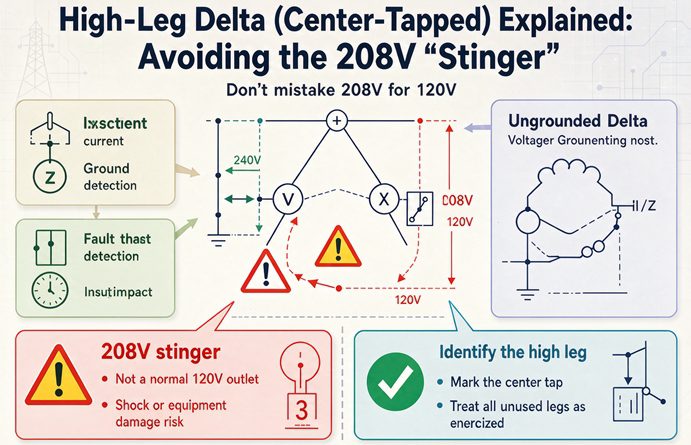
A high-leg delta is a 240 volt delta with the midpoint of one winding grounded. That midpoint becomes the neutral, so two legs read 120 volts to it and 180 degrees apart, while the third reads 208 volts because it sits at the altitude of the triangle. Nothing is broken. But only one third of the kVA can reach 120 volts.
That last sentence is the part most explanations leave out. The geometry is easy and everybody covers it. What nobody puts a number on is the bill: you buy a 75 kVA transformer and discover that the 120 volt load, the lights and the receptacles and the control power, has a hard ceiling at 25 kVA. The other 50 kVA is three-phase only. It is not a defect and it is not a wiring mistake. It is what a center tap on one winding out of three means, and it is the single most useful thing to know before you order one.
Here is the whole system in five numbers, using a 75 kVA unit because it is the size that shows up most often in a shop that inherited one.
| Quantity | Value on a 75 kVA unit | Where the number comes from |
|---|---|---|
| Line-to-line voltage | 240 V | the winding design, all three pairs |
| Line-to-neutral, phases A and C | 120 V | half of the center-tapped winding |
| Line-to-neutral, phase B | 207.8 V | 240 times 0.866, the altitude of the triangle |
| Line current at full load | 180.4 A | 75,000 divided by 1.732 times 240 |
| 120 V load the unit can carry | 25 kVA | one winding out of three |
Read that last row twice. It does not say 75 kVA. It says 25, and that is the number that decides whether a high-leg service is right for a building.
What the transformer is actually doing
One winding out of three got grounded in the middle
A 240 volt delta secondary has three windings connected end to end in a triangle. Each winding is rated at one third of the nameplate, so on a 75 kVA unit each winding is a 25 kVA winding carrying 104.2 amps.
Now pick one of the three windings, usually the one between A and C, and bring out a wire from the exact middle of it. Bond that wire to ground. That wire is now the neutral, and everything else follows from that one decision.
The half of the winding from A to the midpoint is 120 volts. The half from the midpoint to C is also 120 volts. Both halves carry the same conductor, so both can pass 104.2 amps, and that is where the 120 volt capacity comes from and also where it stops.
The critical thing to notice is that A and C are not two phases of a three-phase set as far as the neutral is concerned. They are the two ends of one single-phase winding, which is why they read 120 volts each to the midpoint and 240 volts to each other. They behave exactly like the two hots of a residential service. The third leg, B, is the odd one out, and it is odd by geometry rather than by design intent.
The altitude of the triangle is the 208
Draw the triangle. A and C sit 240 volts apart. B is the third vertex. The neutral is the midpoint of the A-C side, so the distance from B to the neutral is the height of that triangle measured from the opposite vertex to the midpoint of the base.
For an equilateral triangle with a side of 240, that height is 240 times the square root of 3 divided by 2, which is 207.85. Round it and you have 208.
You can check it without any trigonometry. The distance from B to the neutral, the distance from the neutral to A, and the distance from B to A form a right triangle. The hypotenuse is 240, one leg is 120, so the other leg is the square root of 240 squared minus 120 squared, which is the square root of 43,200, which is 207.85. Same answer, and it is the check I use when somebody quotes a different number.
In phasor terms, put A at 120 volts and zero degrees. Then C is at 120 volts and 180 degrees, because it is on the far side of the same winding. B lands at 207.8 volts and 90 degrees. That 90 degrees is the whole story of this system, and I will come back to it when we get to neutral current, because it explains a failure mode that has nothing to do with the 208 volts everybody worries about.
Why there is no 480 volt version
People ask for a 480 volt high leg, usually because they have seen 277 somewhere and assume the pattern repeats. It does not. 277 is 480 divided by the square root of 3, which is a wye quantity, and it comes from a 480Y/277 service with a real neutral point at the center of a star.
A high leg needs a winding with a midpoint available, and at 480 volts the delta cousins are the corner-grounded delta and the ungrounded delta. Neither one produces a high leg, because neither one grounds the middle of a winding. A corner-grounded delta grounds one corner, so one phase reads zero to ground and the other two read 480. An ungrounded delta has no defined voltage to ground at all until something faults.
So the high leg is a 240 volt animal. It exists because 240 volt three-phase motors and 120 volt lighting were both needed in the same building in the middle of the last century, and one transformer with a center tap was cheaper than two transformers. That is the entire historical reason, and it is worth saying plainly because it explains why the system is common in shops built before about 1980 and rare in anything newer.
Why the number is 208 and never anything else
The stinger tracks the line voltage, it is not regulated
The 208 is not a setpoint. It is 0.866 times whatever the line-to-line voltage happens to be that day, so it moves with the service voltage and it moves further than the 120 volt legs do.
| Line-to-line | A and C to neutral | B to neutral | B divided by A |
|---|---|---|---|
| 228 V | 114.0 V | 197.5 V | 1.732 |
| 240 V | 120.0 V | 207.8 V | 1.732 |
| 246 V | 123.0 V | 213.0 V | 1.732 |
| 252 V | 126.0 V | 218.2 V | 1.732 |
The ratio never changes. That is the useful part of the table: whatever you measure on A to neutral, multiply by 1.732 and you have what B should read. If it does not, something is wrong with the winding or with your meter, and it is not a rounding error.
The 228 and 252 rows are the Range A service limits for a 240 volt nominal service under ANSI C84.1. At the low end the stinger reads 197.5, and at the high end it reads 218.2. So a technician who has been told “208 volts, plus or minus five percent” will find that band holds, but not because the stinger has its own tolerance. It holds because the line voltage band is plus or minus five percent and the stinger simply scales with it.
The reading that sends people looking for a fault
Three readings, two at 120 and one at 208, is a healthy high-leg service. It is also the exact signature a technician sees when they expect a 208Y/120 wye and find something that does not match, and the usual first reaction is that a winding is failing or that the transformer is single-phasing.
It is neither. The transformer is doing precisely what a center-tapped delta does. The way to settle it in thirty seconds is to measure line to line as well. On a wye, line-to-line is 1.732 times line-to-neutral, so 120 to neutral means 208 between phases. On a high-leg delta, line-to-line is 240 on all three pairs and line-to-neutral is 120, 208, 120. The line-to-line reading is what separates the two systems, not the line-to-neutral reading.
There is a second consequence that catches people during a survey. On a high-leg system the highest voltage to ground anywhere in the building is 208, not 240. So the insulation coordination is set by 208 volts to ground, and a 240 volt class panel is correct. It also means a 600 volt rated meter is generous, and a 300 volt rated meter is still adequate, which is why the work does not feel dangerous right up until somebody lands a 120 volt circuit on the wrong bus.
Read any panel in thirty seconds
The voltage signature is the fastest way to identify a service you have never seen, and it works across every low voltage system in North America. Measure each conductor to the neutral or ground, then measure between conductors. Six rows cover almost everything you will meet.
| Reading to neutral | Reading between conductors | What you have |
|---|---|---|
| 120, 120, 120 | 208 on all three pairs | 208Y/120 wye, four wire |
| 120, 208, 120 | 240 on all three pairs | 240 volt high-leg delta, four wire |
| 0, 240, 240 | 240 on all three pairs | corner-grounded 240 volt delta, three wire |
| 277, 277, 277 | 480 on all three pairs | 480Y/277 wye, four wire |
| unstable, anywhere from 0 to 480 | 480 on all three pairs | ungrounded 480 delta, three wire |
| 120, 120, and no third conductor | 240, 120, 120 among the three terminals | single-phase 120/240, three wire |
The last row is the one that saves arguments. A single-phase three-wire service has two hots and a neutral, and if you count the three terminals as if they were phases you will measure 120, 120, and 240, which looks like a delta until you notice that one of the three pairs is not 240. There is no third phase to measure. Somebody labelling that panel as three-phase is how a three-phase load ends up on a single-phase service.
The ungrounded row is deliberately vague. With no intentional ground connection, the voltage from any conductor to ground is set by capacitance and by whatever leakage exists, so a meter can read almost anything and still be telling the truth. That is not a fault, it is the system working as designed, and it is exactly why the code wants a ground detector on those systems rather than a voltmeter reading.
The capacity you actually bought
One third, and why it is not a separate budget
The clean statement is that all of the 120 volt load on a high-leg service comes off the center-tapped winding, and that winding is one of three, so the ceiling is one third of the nameplate. Here is what that looks like across the sizes that show up in real buildings.
| Nameplate kVA | Line current at 240 V | Current per winding | 120 V ceiling | 120 V current per leg |
|---|---|---|---|---|
| 15 | 36.1 A | 20.8 A | 5.0 kVA | 20.8 A |
| 25 | 60.1 A | 34.7 A | 8.3 kVA | 34.7 A |
| 37.5 | 90.2 A | 52.1 A | 12.5 kVA | 52.1 A |
| 50 | 120.3 A | 69.4 A | 16.7 kVA | 69.4 A |
| 75 | 180.4 A | 104.2 A | 25.0 kVA | 104.2 A |
| 112.5 | 270.6 A | 156.3 A | 37.5 kVA | 156.3 A |
| 150 | 360.8 A | 208.3 A | 50.0 kVA | 208.3 A |
| 225 | 541.3 A | 312.5 A | 75.0 kVA | 312.5 A |
| 300 | 721.7 A | 416.7 A | 100.0 kVA | 416.7 A |
The relationship is exact, not approximate. The 120 V ceiling is always one third of the nameplate, and the 120 V current per leg is always the line current divided by 1.732, which is the same as the winding current. Both columns are the same number for the same reason.
Now here is the part that the clean statement hides. The 120 V load and the three-phase load are not separate budgets. They both flow through that center winding. Put 25 kVA of lighting on the center winding and 50 kVA of three-phase load through the transformer, and the center winding carries its share of the three-phase current plus the lighting current, which is about 16.7 kVA plus 25 kVA, or 41.7 kVA through a winding rated 25. The nameplate total of 75 kVA is not exceeded, but one winding is at 167 percent and it will run hot and fail early.
So the working rule is not “one third of nameplate for 120 volts”. It is “one third of nameplate for 120 volts if you have no three-phase load at all”, and less than that as the three-phase load grows. On a shop with real motor load, keeping the 120 V total under a quarter of nameplate is the honest target, and then checking the winding current directly is the only way to be sure.
What the same money buys in a wye
A 75 kVA 208Y/120 transformer delivers 208 amps per phase, and all three phases can carry 120 volt load. That is 25 kVA per phase and 75 kVA of 120 volt load in total, against 25 kVA on the high-leg version.
Three times the 120 volt capacity for the same nameplate, same box, roughly the same price. What the wye gives up is 240 volt three-phase, which it simply does not have. It gives 208 volts three-phase instead, and a 240 volt motor does not want 208.
That trade is the entire decision. If the building is mostly motors at 240 volts with a little lighting, the high leg is a good fit and has been for seventy years. If the building is mostly 120 volt load with a little three-phase, the high leg is the wrong tool and always was, and the fact that it is already installed is a sunk cost rather than a reason to keep it.
The 120 V ceiling in amps, which is easier to use in the field
The table above gives kVA, and kVA is what a panel schedule does not show. What a panel schedule shows is amps per breaker. So the practical version of the rule is that the total 120 volt load, added up as amps on A plus amps on C, cannot exceed twice the winding current. On a 75 kVA unit that is 208 amps of 120 volt load split between the two legs, or 104 amps on each leg if you want it balanced.
Two hundred and eight amps of 120 volt load sounds like a lot until you price a lighting retrofit. A hundred and four amps per leg is five 20 amp circuits per leg with nothing to spare, or about 25 kW of load at a power factor near one. For a shop with a couple of hundred feet of office and a few dozen high bays, that is not generous, and it is the number that turns into a second transformer.
Fourteen dead spaces in a forty-two space panel
A three-phase panelboard alternates its spaces A, B, C, A, B, C. On a 42 space panel that puts 14 spaces on each phase, and the 14 that land on B are unusable for 120 volt circuits because B to neutral is 208 volts.
That is not a wiring inconvenience. It is a purchasing consequence. You buy a 42 space panel, and the load you have the most of can only use 28 of the spaces. The 14 B spaces can carry two-pole and three-pole breakers, so they are not wasted if you have 240 volt single-phase or three-phase branch circuits to put there. In a shop with a lot of 240 volt equipment they get used. In an office with mostly 120 volt circuits they sit empty, and the panel is effectively a 28 space panel that cost the same as a 42.
There is a second, quieter cost. Every one of those 14 spaces is a place where somebody can land a 120 volt circuit on the wrong bus, and the failure is immediate and loud. The 208 volts does not degrade a 120 volt load gently. A resistive load draws three times its rated power, since power goes as voltage squared and 208 divided by 120 is 1.733, squared is 3.00. A 100 watt lamp becomes a 300 watt lamp, and a filament designed for a third of that flashes instead of glowing. An electronic driver with a 120 volt only nameplate usually fails at the input capacitor before the fuse clears.
That is why the code does not rely on people being careful. It requires the conductor to be orange at every point where a connection is made, and it requires the enclosure to carry a warning with the actual voltage written into it. On a system where the wrong bus is one space away from the right one, labelling is the control, and it has to survive the next remodel.
The neutral is not what you think
A and C cancel, because they are 180 degrees apart
Put 30 amps of 120 volt load on A to neutral and 30 amps on C to neutral, and measure the neutral. You get zero. Not approximately zero, zero, because those two currents are 180 degrees apart and the neutral carries the difference. This is exactly how a residential 120/240 service behaves, and it is why high-leg panels work well for lighting: you pair A and C and the neutral stays quiet.
That also means the neutral can be smaller than the phase conductors, because its maximum current is the imbalance between the two legs, not the sum. On a 75 kVA unit the worst case is one leg fully loaded and the other idle, which is 104.2 amps, so a neutral sized at 115 amps covers the winding’s full capability. The service neutral still has to satisfy the rules for the service, and the calculated load still has to be done properly, but the physics here is friendly.
B does not cancel, and that is the trap
Now put 30 amps on A to neutral and 30 amps on B to neutral and measure the neutral again. You get 42.4 amps, which is 30 times the square root of 2, and it is larger than either of the two hot conductors feeding it.
The reason is the 90 degrees from earlier. A to neutral is at zero degrees, B to neutral is at 90, so the two currents add at right angles and the result is the hypotenuse. A neutral sized for the larger of the two circuits, which is what a shared neutral usually gets, is now undersized by 41 percent.
This is the failure mode nobody warns about, because it does not announce itself. Nothing trips, nothing sparks, the circuits work. The neutral runs hot, the insulation ages, and somewhere down the line a connection that has been running over its rating for years opens up under load. On a high-leg system, the rule is simple and absolute: a neutral is shared between A and C, or it is not shared at all. Never put B on a shared neutral.
Three-phase multiwire is off the table
Commercial lighting design leans on the three-phase multiwire branch circuit, one neutral shared by three 120 volt circuits on A, B, and C. It saves copper and it works because the three currents are 120 degrees apart and sum to zero when balanced.
On a high-leg system that circuit cannot exist. Two of the three legs are 180 degrees apart and the third is at 90, so there is no set of three 120 volt circuits that cancels. Worse, the B leg is not a 120 volt circuit at all, so a three-pole breaker with a shared neutral would put 208 volts across one third of the lighting.
What you get instead is two-wire circuits, or A-C pairs sharing a neutral, which is fine and is what most of these buildings actually have. It just means the circuit count per panel is lower than a lighting designer would expect, and the feeder neutral is sized from a calculation that assumes no cancellation from the third phase.
The breaker that fits and is not rated
240.85 in one sentence
A circuit breaker with a slash rating, like 120/240, is rated for the lower number as its voltage to ground. Section 240.85 does not allow it where the voltage to ground exceeds that lower value.
On the high leg, the voltage to ground is 208. A 120/240 slash rated single-pole breaker is rated for 120 volts to ground. It fits the bus, it looks right, and it is not permitted, and the reason is not bureaucratic: the insulation and the interruptible rating inside that breaker were qualified at 120 volts to ground.
A straight rated 240 volt breaker, marked 240 with no slash, is fine on B to neutral and on any two phases. Two-pole and three-pole 240 volt breakers are usually straight rated, so A-B, B-C, A-C, and any three-phase circuit are not affected. The problem is confined to single-pole breakers on B and to the tandem and quad breakers that put two circuits on one space.
That last one is worth spelling out. A quad breaker with two 120/240 single-pole sections and one two-pole section is a common way to add circuits without adding spaces. Land one of its single-pole sections on a B space and you have installed two violations in one device, on a circuit that will read 208 volts to neutral and will work right up until it is loaded.
What to order instead
For 120 volt circuits, use A and C only, and use the breakers the panel is listed for. For 240 volt single-phase, any two phases. For three-phase, all three, with a straight rated three-pole breaker.
For the rare case where you genuinely need a 208 volt line-to-neutral circuit on B, which is a bad idea for reasons in the next section, you need a single-pole breaker straight rated at 240 volts, and those exist but are not what the supply house hands you when you ask for a single pole.
The label on the panel is not optional
Section 408.3(E) puts the high leg on the B phase in panelboards and switchboards, with an exception for metering equipment and for switchboards and switchgear with a metering section. That exception matters in the field, because utilities frequently want the high leg on C at the meter. The rule does not travel with the wire. Once the conductors leave the metering section, B is B again.
Section 408.3(F)(1) requires a field applied warning on the enclosure in the form of a sentence naming the phase and the voltage, something like “Caution B phase has 208 volts to ground”, with the blanks filled in from the actual measurement. Editions differ on exactly where this sits and how it is worded, so check the edition your authority having jurisdiction enforces, but the intent is stable: the person opening the panel should not have to know the geometry to avoid the mistake.
One claim worth correcting, because it circulates widely. The code requires the high leg to be orange. It does not assign colors to A and C. The black, orange, blue arrangement you see in photographs is a convention on top of the requirement, and in some shops A and C are black and red. So do not read the absence of blue as a defect. Read the presence of orange as the requirement, and read its absence at any termination as the defect.
208 volts is not a 208Y/120 supply
The same number in two different places
A 208 volt single-phase load, an air conditioner or a baseboard heater, is rated at 208 volts line to line on a 208Y/120 system. On a high-leg delta, 208 volts appears line to neutral on B, and the temptation is to conclude that the load can go there because the number matches.
It cannot, and there are three separate reasons. The breaker has no rating for it, as above. The neutral is not a 208 volt circuit conductor in this system, it is the midpoint of a 240 volt winding, so a 208 volt load from B to neutral puts the load current through half a winding that was sized for the 120 volt load. And the circuit itself is a line-to-neutral circuit on a system whose line-to-neutral voltages are not a set, so there is no second phase to return on and no way to balance it.
The right way to serve a 208/230 rated single-phase load on a high-leg service is across any two phases, at 240 volts. That is within the utilization range of a 208/230 unit, which is typically 197 to 253 volts. A unit marked 208 only, with no 230, is a different animal and should not see 240.
Equipment listing
A panelboard or switchboard marked 208Y/120 is not suitable for a 240 volt high-leg service, even though the highest voltage to ground is only 208. The marking describes the system, not just the insulation. What you need is equipment marked 240/120 volt, three-phase, four-wire, or 240 volt delta four-wire.
This comes up when somebody replaces a panel and orders the common 208Y/120 catalog number because it is in stock. The bus is rated for 208 between phases. On a high-leg service it will see 240 between phases on every pair. That is not a marginal call.
Ordering one, and replacing one
The nameplate language that gets you the right machine
Ask for 240 volt delta, four wire, center tapped, or 240/120 volt three-phase four wire. The words that matter are four wire, because they mean a neutral terminal exists, and center tapped, because it says where the neutral comes from.
What you do not want is 240 volt delta three wire. That unit has three secondary terminals and no neutral, and it cannot become a high-leg unit later. This is the most expensive misunderstanding in the whole subject, because the two units look identical from the outside and the price difference is small, and the mistake is only discovered when somebody goes looking for the neutral terminal and finds a blank plate.
A 208Y/120 unit is a different machine again, with a wye secondary and 208 between phases. It cannot be reconnected into a high-leg delta by moving links, because the windings are not the same windings.
You cannot add a center tap afterwards
There is no field modification that turns a three-wire delta secondary into a four-wire one. The center tap is a brought-out lead from the middle of a winding, made when the winding is built. Nothing you can do in the cabinet creates it.
So the question “can we just ground the middle of one winding” has a short answer, and it is the answer that turns a repair into a replacement. If the unit in the building is a three-wire delta and the building needs 120 volts, the options are a separate single-phase transformer for the 120 volt load, a new four-wire unit, or a different service. All three are real projects, and none of them is a jumpers-and-labels job.
Three single-phase units make one
The original way these were built, and still the way a lot of them get repaired, is three single-phase transformers in a bank. Each one is a 240/120 volt unit with a center-tapped secondary, they are connected delta on the secondary side, and the center tap of one of them becomes the system neutral.
That is also why the repair path exists. If one unit in the bank fails, you replace one transformer, not the whole assembly, and you reconnect the same way. The catch is that the bank has to be reconnected exactly, because reversing the polarity of the center-tapped unit shifts the neutral point and produces a panel whose readings do not match the table above, which is a genuinely confusing panel to troubleshoot.
Open delta and the 57.7 percent
Two transformers instead of three is a common arrangement where the three-phase load is small, and it is still a high-leg system if the center-tapped unit is one of the two. The capacity is the surprise.
Two 25 kVA units in open delta deliver 43.3 kVA of three-phase, not 50, because the line current is limited to one transformer’s 104.2 amps and the three-phase kVA is 1.732 times 240 times 104.2. That is 57.7 percent of the 75 kVA a closed bank of three would give, and it is the number to have in your head when somebody says the third transformer was removed for spare capacity.
Open delta also regulates worse under unbalanced load, because the two transformers see different impedances depending on which phase the load is on. And the center-tapped unit, the one carrying the 120 volt load, is the one that has to be larger, which is why the bank often looks like one big transformer and one small one rather than two equal ones. That asymmetry is a signature, not a mistake.
Feeder, neutral, and device sizing at 240 volts
Three near misses in one column
Take the full load current, apply the 125 percent for a continuous load, and land on the next standard device rating from Section 240.6(A). On this voltage, three of the standard sizes land a fraction of an amp past a standard rating and jump a whole frame.
| Nameplate | Full load current | 125 percent | Nearest standard below | Device you end up with |
|---|---|---|---|---|
| 50 kVA | 120.3 A | 150.4 A | 150 A | 175 A |
| 75 kVA | 180.4 A | 225.5 A | 225 A | 250 A |
| 150 kVA | 360.8 A | 451.1 A | 450 A | 500 A |
| 300 kVA | 721.7 A | 902.1 A | none, 900 is not a listed rating | 1,000 A |
The first three are the interesting ones. Half an amp over 225 is the same as a hundred amps over, as far as the selection goes, and the next frame up is a different breaker, a different lug, a different enclosure, and often a different delivery date. The 300 kVA row is not a near miss at all, because 900 amps is not one of the standard ratings, so 902.1 goes to 1,000 on its own merits.
If you are checking a design somebody else did and the device is 225 amps on a 75 kVA unit, the arithmetic was done on the nameplate current and the 125 percent was skipped. That is worth a question, because the answer is either a corrected schedule or an explanation of why the load is not continuous.
Conductor and neutral
A 75 kVA unit needs 225.5 amps of conductor ampacity for a continuous load. Four aught copper at 75 degrees C is 230 amps and works. Three aught is 200 and does not. On the line side, the same arithmetic at the primary voltage, and the primary device follows the transformer protection rules rather than the load rules.
The neutral, as above, carries at most the imbalance between A and C, which on a 75 kVA unit is 104.2 amps, so a number two copper at 115 amps covers it. That feels small next to four aught phase conductors, and it is correct, and it is also the reason a well meaning upgrade to a full size neutral is not wrong, just unnecessary. What is wrong is a neutral sized for the larger single circuit on a shared run that also carries B, which is the 42.4 amp case from earlier.
Fault current is the good news
A 75 kVA transformer at 240 volts with 3.5 percent impedance delivers about 5,155 amps of fault current at the secondary terminals. At 2.5 percent it is 7,217. Compare that with the same kVA at 480 volts, where the current is half and the available fault current at the panel is set by the source rather than the transformer, and with a 1,000 kVA unit at 480 where the conversation starts at 20,000 amps.
Low voltage means low fault current. A 10 kA panel is generous on most high-leg services, series rated equipment is easy to apply, and the arc flash energy at the panel is modest by commercial standards. That is a real advantage of 240 volt distribution and it is the reason some plants keep these services alive: the equipment downstream is cheap and the incident energy is low.
Motors, drives, and control power
A three-phase motor never sees the stinger
A three-phase motor has three leads and no neutral, so the 208 volts to ground does not appear anywhere in its circuit. It sees 240 volts between phases, which is its nominal rating, and it runs.
What does not work is a motor rated 208 volts only, with no 230 on the nameplate. At 240 it is 15 percent over nameplate, the flux saturates, the current rises faster than the torque, and the winding runs hot. A motor marked 208-230 is fine, and most commercial HVAC equipment is marked that way for exactly this reason.
Drives are fine, with one condition
A 240 volt class drive, the 200 to 240 volt input family, is designed for this line-to-line voltage and does not care what the line-to-ground voltage is on any one leg. It rectifies line to line. So a drive on a high-leg service works.
The condition is control power. Do not take 120 volt control from B to neutral, and do not let anybody talk you into it because the drive has a 120 volt control terminal. Take control power from a transformer with its primary across two phases at 240 volts, or from A to neutral.
Control transformers have a preferred connection
A 240 to 120 volt control transformer with its primary across A and C sees 240 volts and delivers 120. Across B and C it also sees 240 and also delivers 120, so that connection is fine too. Across B and neutral it sees 208, and a 240 volt primary on 208 delivers about 104 volts on a 120 volt secondary, which is enough for some contactors and not enough for others, and the ones it is not enough for chatter until they weld.
The rule that prevents all of this is one sentence: a control circuit never includes the neutral on a high-leg system. Line to line, always.
Rotation is not changed by the high leg, but the panel position is
The high leg is a grounding decision, not a phase sequence decision. A motor turns the same direction it would on any other 240 volt delta with the same phase order, so nothing about the high leg reverses a pump.
What does change is which conductor is in which position. The high leg is B in the panel by code, and it may be C at the meter by utility practice, and at the transformer it may be labelled something else again. So the only reliable check before starting a motor with a required direction is a rotation meter at the motor, not a comparison of panel labels.
Keep it, or replace it
Four questions, in this order, settle it.
Is the 120 volt load more than a quarter of the nameplate? If yes, the center winding is already working harder than its rating when the three-phase load is also running, and the unit is a candidate for replacement regardless of how it tests. If the 120 volt load is a few amps of control power and a handful of receptacles, the high leg is doing its job.
Is the three-phase load mostly 240 volt motors? If yes, the high leg is the cheapest correct answer, because a 208Y/120 service would require either replacing the motors or adding a step-up transformer, and both cost more than living with the panel quirks.
Is the 120 volt load mostly lighting and receptacles, with new tenants who will add more? Then the fourteen dead spaces and the 208 volt trap become a maintenance cost that never goes away, and the honest comparison is against a 208Y/120 service with a small 240 volt subservice for the motors that need it.
Is the service over 400 amps? At that size the panel space loss and the breaker rating restrictions stop being annoyances and start being design constraints, and the economics of replacement improve because the equipment downstream is being replaced anyway.
There is no universal answer. What there is, is a number: one third of the nameplate, and a panel where one third of the spaces cannot carry your most common circuit. Those two facts decide more installations than any argument about safety, because they are the ones that show up on a schedule and in a purchase order.
FAQ
Why does the high leg read 208 volts to neutral?
Because it sits at the altitude of a triangle whose sides are 240 volts. The neutral is the midpoint of one winding, so the distance from the opposite phase to that midpoint is 240 times 0.866, which is 207.8. The right triangle check, the square root of 240 squared minus 120 squared, lands in the same place. It is geometry, not a fault.
Is 208 volts on the high leg dangerous?
It is dangerous to equipment, not to a qualified person with the right meter. The risk is a 120 volt circuit landed on the B bus, which puts 208 volts across a load designed for 120 and destroys it, often before the breaker clears. A resistive load draws three times its rated power there. The 208 volts itself is normal on every healthy service.
Can I use the high leg for a 120 volt circuit?
No. The voltage is 208, not 120, and the circuit would destroy whatever is plugged into it. Section 240.85 also does not allow a 120/240 slash rated single-pole breaker where the voltage to ground is 208, so the breaker itself is not rated for the application. On a high-leg panel, 120 volt circuits go on A and C only, and the B spaces carry two-pole and three-pole circuits.
What color does the code require for the high leg?
Orange. Section 110.15 requires a durable orange finish or another effective means of identification, applied at each point where a connection is made if the neutral is present, and Section 230.56 applies the same to service conductors. The code does not assign colors to the other two phases. Black, orange, blue is a common convention on top of the requirement, not the requirement itself.
Why must the high leg be the B phase?
Section 408.3(E) requires it in panelboards and switchboards so that anyone opening a panel finds the unusual voltage in the same place every time. There is an exception for metering equipment and for switchboards with a metering section, because utilities often want the high leg on C at the meter. The exception stops at the metering section. Once the conductors leave it, the high leg is B again.
Can I feed a 208 volt single-phase load from B to neutral?
The voltage matches, but the circuit is not a legal or sensible one. No standard single-pole breaker is rated for 208 volts to ground on this system, the neutral is the midpoint of a 240 volt winding rather than a 208 volt circuit conductor, and there is no second phase to balance against. Serve a 208/230 rated load across any two phases at 240 volts instead, which is inside its utilization range.
How much 120 volt load can a high-leg transformer carry?
One third of the nameplate at most, because the 120 volts comes off the center tap of one winding out of three. A 75 kVA unit therefore has a 25 kVA ceiling on all 120 volt load combined, which is 208 amps at 120 volts split between the two legs. That ceiling shrinks as three-phase load grows, because the same winding carries its share of the three-phase current too.
What size breaker goes on a 75 kVA high-leg transformer?
A 75 kVA unit at 240 volts draws 180.4 amps, and 125 percent of that is 225.5, which is half an amp above the 225 amp standard rating, so the device is 250 amps. The same near miss happens at 50 kVA, where 150.4 amps pushes past 150 to 175, and at 150 kVA, where 451.1 pushes past 450 to 500. Always run the 125 percent before picking from the standard ratings.
Can I convert a three-wire delta transformer to a high leg?
No. The center tap is a lead brought out from the middle of a winding when the winding is built. A three-wire 240 volt delta unit has no neutral terminal and no way to create one in the field. The options are a separate single-phase transformer for the 120 volt load, a new four-wire unit, or a different service, and all three are projects rather than modifications.
What is the difference between a high-leg delta and a corner-grounded delta?
A high-leg delta grounds the midpoint of one winding, so two phases read 120 volts to ground and the third reads 208. A corner-grounded delta grounds one phase end, so that phase reads zero to ground and the other two read the full 240. Corner grounding gives no 120 volts at all, needs straight rated breakers on every pole, and is used to save a pole of switching rather than to supply lighting.
Does a high-leg delta affect motor rotation?
No. The high leg is a grounding choice, not a phase sequence choice, so a motor turns the same direction it would on any other 240 volt delta with the same phase order. What does change is which conductor sits in which position, since the high leg is B in the panel by code and may be C at the meter by utility practice. Check rotation with a meter at the motor before first start.
Why does the high leg exist at all?
Because one transformer with a center tap was cheaper than two transformers. A shop needed 240 volts three-phase for motors and 120 volts for lighting, and a center-tapped delta gave both from a single bank. That economics drove a generation of construction before about 1980. The system survives because replacing it means replacing every panel and every 240 volt motor circuit, which is a bigger job than living with the quirks.