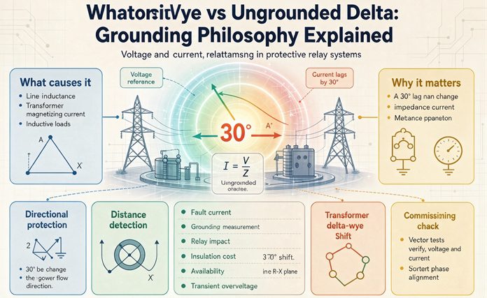
Grounding does not make a system safe. It makes a system readable. A solidly grounded wye turns a ground fault into current, and a breaker reads it. An ungrounded delta turns the same fault into a voltage shift, and a lamp or a relay reads it. Choose the sensor first. Detection, duration, overvoltage and cost all follow from that one choice.
Most of the writing on this subject is a list of advantages and disadvantages, and lists are useless at the moment you have to sign a purchase order. What you need is a way to see that the two schemes are not two degrees of safety. They are two different instruments pointed at the same event, and each instrument has a blind spot with a number attached.
This page puts numbers on both blind spots, then works through what each one forces you to buy.
The philosophy fits in one sentence
Every grounding scheme answers a single question: when insulation fails and a live conductor touches steel, what changes in the system, and who is watching that particular thing?
On a solidly grounded wye, current changes. A lot of current, in a path that a circuit breaker already monitors for other reasons. The sensor is a current transformer, and you probably already own it.
On an ungrounded delta, voltage changes. Almost no current flows, so no breaker notices anything, but the voltage from each phase to ground moves in a pattern that a voltmeter or a voltage relay can read clearly.
That is the entire philosophical difference. Everything else, whether the lights stay on, how big the arc is, what the electrician has to carry, how much the switchgear costs, follows from which of those two quantities you decided to measure.
Grounding is a sensor decision
Once you frame it that way, some things that get argued about for decades stop being arguments.
The grounded wye does not prevent ground faults. It makes them loud. A 480Y/277 service with a 20,000 amp available fault current will clear a bolted ground fault in a few cycles and will also produce an arc flash that will put a person in a burn unit. The system did its job. The job was detection, not protection.
The ungrounded delta does not prevent arcs either. It removes the fault current, which removes the arc energy, and then it hands you a fault that stays on the system for as long as it takes someone to find it. If nobody finds it, the fault is still there next year.
Neither of those is a moral position. They are two different trades: certainty now versus continuity now.
The three questions every scheme answers
If you are comparing grounding schemes for a project, three questions settle it. Everything else is detail.
- What is the voltage to ground on a healthy phase?
- When one phase faults to ground, what happens to the other two?
- Who finds the fault, and how long do they have?
Answer those three for each scheme and the selection stops being philosophical.
| What you need to know | Solidly grounded wye, 480Y/277 | Ungrounded delta, 480, 3 wire | High-resistance grounded wye, 480Y/277, 5 A |
|---|---|---|---|
| Voltage to ground, healthy | 277 V, fixed by the winding | floats near 277 V, set by cable capacitance | 277 V, fixed by the winding |
| Voltage to ground, one phase faulted | 0 on the faulted phase, 277 on the other two | 0 on the faulted phase, 480 on the other two | 0 on the faulted phase, 480 on the other two |
| Current in the fault | up to 20,918 A at 1,000 kVA and 5.75 percent impedance | 0.2 to 5 A, charging current only | 5 A, set by the resistor |
| Does anything trip | yes, in cycles | no | no |
| What finds the fault | the breaker, or the service ground-fault relay | a ground detector, 59N or three lamps | 59N, then a pulsing locator |
| How long the fault can sit there | milliseconds | months | hours to days |
Read the third column against the second. They are identical in the two rows that describe voltage, and that is not a mistake in the table. It is the single most misunderstood fact in this whole subject, and section six comes back to it.
Ungrounded is a lie, and the lie matters
There is no such thing as an ungrounded system. Every three-phase system has capacitance from each phase conductor to the conduit, the raceway, the building steel, the shields, and the earth. At 60 Hz that capacitance is not a small effect. For a plant-scale system it can amount to tens of ohms.
So the system does have a ground reference. It is made of cable instead of copper, and it moves whenever anything touches ground. That is why the phrase “capacitively grounded” shows up in the better handbooks, and why a healthy ungrounded delta reads a stable 277 volts on all three phases with an ordinary meter.
Two practical consequences follow, and both cost people money.
The first is that the meter reading tells you nothing. A healthy ungrounded delta and a solidly grounded wye both read 277 volts phase to ground. The readings look the same because the physics that produces them looks the same at that instant.
The second is that the “no current flows” promise has a size limit. It is true for a small system. It stops being true for a big one, and the crossover is not far away. Section four puts a number on it.
The voltages, before anything else
Almost every argument about grounding turns into an argument about a number somebody half remembers. Here are the numbers.
Where 277 comes from
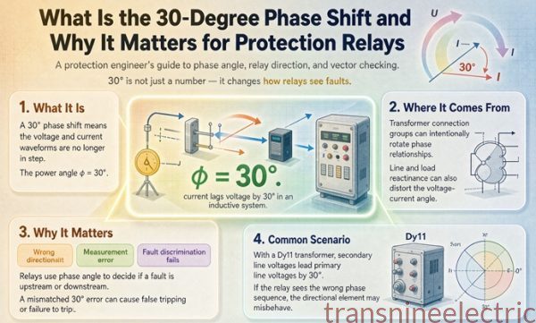
277.1 volts is 480 divided by 1.732. The 1.732 is the square root of three, and the square root of three is twice the cosine of 30 degrees, which is the same triangle that produces the 30 degree phase shift across a delta-wye transformer. One triangle, two outputs: a magnitude ratio and an angle.
Divided the other way, 277 is 57.7 percent of 480. A grounded wye holds every phase at 57.7 percent of the line-to-line voltage, all the time, whether the system is healthy or faulted.
That 57.7 percent is a real engineering benefit, and at 480 volts it is worth exactly nothing. Both a grounded wye and a delta at 480 use 600 volt class insulation, because 600 volts is the bottom rung of the low voltage ladder. The 57.7 percent argument pays off at medium voltage, where a grounded 13.8 kV system can use 8.7 kV class insulation and arresters instead of 15 kV class. At 480, you buy the same gear either way. People repeat the argument at low voltage because they read it in a medium voltage book.
The 1.732 that shows up on the other two phases
When one phase goes to ground on a system whose ground reference is not at the neutral, the other two phases rise. Not slightly. To full line-to-line voltage.
| Scheme | Healthy phase to ground | One phase faulted, other two to ground | Rise |
|---|---|---|---|
| 480Y/277 solidly grounded | 277 V | 277 V | none |
| 480 delta, ungrounded | about 277 V | 480 V | plus 73 percent |
| 480 delta, corner grounded | 0, 480, 480 | no change | plus 73 percent, all the time |
| 480Y/277 with a 5 A resistor | 277 V | 480 V | plus 73 percent |
| 240 delta, center tapped high leg | 120, 120, 208 | varies | 73 percent on one phase |
The corner-grounded row is the one that ends careers. On a corner-grounded 480 volt delta, two of the three phases sit at 480 volts to ground during normal, healthy operation, forever. Every piece of gear downstream has to be rated for that, and most of it is not.
The resistor row is the one that gets argued about. Hold that thought.
What 480 volts does to a part rated for 277
This is the paragraph that turns a grounding discussion into a purchase order.
Metal oxide varistors on a 480Y/277 panel are chosen with a maximum continuous operating voltage around 320 volts, sometimes 275. They are correct for a solidly grounded system, where 277 is the highest voltage they will ever see for more than a few milliseconds.
Put that same panel on a source where a ground fault pushes the healthy phases to 480 volts and holds them there, and the varistor conducts continuously. It heats, it degrades, and it fails short. The failure is a second ground fault, on a different phase, usually at the far end of the same bus. That is how a grounding change becomes a fire.
The same trap exists in variable frequency drives. Most drives have phase-to-ground capacitors in their EMI filter, and those capacitors are rated against the phase-to-ground voltage of the supply they were specified for. Move the drive to a corner-grounded or high-resistance grounded source and the filter sees 480 volts during a fault. Many drives have a jumper or a filter option for exactly this. It is in the manual, and it is almost never in the submittal.
Pilot lamps are the cheap version of the same mistake. A 100 watt, 277 volt lamp has a resistance of about 767 ohms. Put 480 volts across it and it dissipates 300 watts, three times its rating, and the filament goes. On a three-lamp ground detector panel fed from a 480 delta, the lamps have to be 600 volt lamps, not 277 volt lamps, or the detector destroys itself the first time it is needed.
The grounded wye, where current is the signal
A solidly grounded wye has a neutral point that is tied to earth with no intentional impedance. That single connection does three things at once: it fixes the phase-to-ground voltage at 57.7 percent of line-to-line, it provides a return path for zero-sequence current, and it makes a phase-to-ground fault look almost exactly like a three-phase fault to the protection.
The fault current is enormous, and that is the mechanism
On a 1,000 kVA unit at 480 volts with 5.75 percent impedance, the full load current is 1,203 amps and a bolted phase-to-ground fault draws about 20,918 amps. Not because the ground connection is special, but because the zero-sequence impedance of a solidly grounded wye is low. The winding is short, the neutral is short, and the return path is the building steel and the service bonding jumper.
| Impedance | Bolted phase-to-ground current, 1,000 kVA at 480 V |
|---|---|
| 5.0 percent | 24,056 A |
| 5.75 percent | 20,918 A |
| 6.0 percent | 20,047 A |
| 8.0 percent | 15,035 A |
That current is the sensor signal. A 1,600 amp frame with a 1,200 amp ground-fault pickup sees 20,918 amps and trips in a cycle and a half. The coordination is easy because the signal is enormous compared with anything else on the system.
The pickup floor nobody puts on the datasheet
Here is the part that the comparison charts leave out.
A protective device does not detect faults. It detects current above a threshold. On a 480Y/277 service of 1,000 amps or more, the code caps the ground-fault pickup at 1,200 amps. Divide the phase voltage by that pickup and you get the resistance ceiling of the sensor.
277 divided by 1,200 is 0.231 ohms.
That is the whole story. Any ground fault with more than a quarter of an ohm in the path cannot produce 1,200 amps, so the relay cannot see it, no matter how good the relay is.
| Ground-fault pickup | Resistance ceiling at 277 V |
|---|---|
| 1,200 A | 0.231 ohm |
| 800 A | 0.346 ohm |
| 600 A | 0.462 ohm |
| 400 A | 0.693 ohm |
Put real numbers on what that means. A one ohm ground fault, which is a corroded lug or a wet connection, passes 277 amps. Nothing operates. A ten ohm fault passes 27.7 amps, which is less than a small motor’s running current. A motor winding leaking 50 milliamps to frame passes 0.05 amps.
The honest conclusion is uncomfortable and it is worth saying plainly: ground-fault protection on a 480Y/277 service is a fire protection device, not a shock protection device. It exists because arcing ground faults at 480 volts start fires, and it catches the ones that are big enough to be arcing. It does not catch the ones that are small enough to be lethal to a person touching a frame, because those are measured in milliamps and the pickup is measured in thousands of amps.
Nothing in the grounded wye design is wrong. It is a matter of understanding what you bought.
Why it won, and it was not safety
Ask why 480Y/277 became the standard in North American commercial buildings and you will usually get an answer about safety. The real reason is cheaper.
277 volts runs fluorescent lighting. One service at 480Y/277 feeds the motors at 480 three-phase and the lighting at 277 single-phase, with no second transformer. A 480 volt delta building needs a separate 480 to 208Y/120 transformer for lighting and receptacles, plus the panel to go with it. That is the argument that decided the standard in the decades after the Second World War, and it is still the argument that decides it today.
The code followed the economics. Ground-fault protection became mandatory for large 480Y/277 services, which made the grounded wye the default for anything big, which made the delta the legacy option by simple attrition. Nobody sat down and concluded that grounding was safer. They concluded that one transformer was cheaper than two, and the safety case got built afterward.
The ungrounded delta, where voltage is the signal
Now the other instrument.
There is no fault current because there is no zero-sequence path
A delta winding has three terminals and no neutral. Zero-sequence current, which is what a phase-to-ground fault produces, has nowhere to leave the winding. It circulates inside the delta and never appears in the line conductors.
So a phase-to-ground fault on the delta side of a transformer draws whatever the system capacitance allows, and nothing else. That is not a design choice or a setting. It is the topology. You cannot tune it, and you cannot make a delta deliver ground-fault current without adding a grounding transformer or grounding a corner.
One corollary catches people on both sides of the transformer. A ground fault on the delta side produces no current on the wye side, and a ground fault on the wye side produces no current on the delta side. The two windings are separate ground-fault domains. That is the continuity selling point and the maintenance problem in the same sentence, because the fault you cannot see from the other side is also the fault that nobody upstream is going to report.
What the detector can see, and it is a lot
The instrument on an ungrounded system is a voltage relay watching the neutral displacement, usually a 59N connected to the broken delta of three voltage transformers, or to the neutral of a grounded-wye VT bank. During a bolted ground fault, the neutral displaces by the full phase voltage, 277 volts. The relay sees that, and it also sees a large fraction of it for faults that no current transformer would ever notice.
The math is a voltage divider. The zero-sequence impedance of the system is the parallel combination of the three phase capacitances, which for 10 microfarads per phase at 60 Hz is 88.4 ohms. The fault resistance sits in series with three times that, because the fault current returns through all three phases.
| Fault resistance | Neutral displacement V0 | As a percentage of 277 V |
|---|---|---|
| 0 ohm, bolted | 277 V | 100 percent |
| 1 ohm | 276.8 V | 99.9 percent |
| 10 ohm | 262 V | 94.7 percent |
| 29 ohm | 197 V | 71.3 percent |
| 100 ohm | 78 V | 28.3 percent |
| 295 ohm | 27.5 V | 9.9 percent |
| 589 ohm | 13.9 V | 5.0 percent |
| 1,000 ohm | 8.2 V | 3.0 percent |
A 59N set at 5 percent of nominal, which is 13.9 volts, detects a fault with 589 ohms in the path. Set at 10 percent, it detects 295 ohms.
Now put the two sensors side by side. The grounded wye’s current sensor sees faults up to 0.231 ohms. The ungrounded delta’s voltage sensor sees faults up to 589 ohms. That is roughly 2,500 times more sensitive in terms of the resistance it can tolerate in the fault path.
That single comparison is the strongest technical argument for the ungrounded delta, and no comparison chart in the top results contains it. The argument is not “no current flows, so nothing gets damaged.” The argument is “the sensor is looking at a different quantity, and that quantity is far more sensitive to a weak fault.”
The catch is what the sensor cannot tell you. V0 tells you a fault exists and roughly how bad the path is. It does not tell you which feeder. On a plant with thirty motor control centers, that is the difference between a two hour job and a two day job, and it is why high-resistance grounding with a pulsing locator exists.
The promise expires at about 5 MVA
The classic case for the ungrounded delta is that the first ground fault does not require shutting anything down. That is true, and it depends on one assumption that is almost never stated: the arc has to go out by itself.
At 480 volts, an arc in the few-amp range is unstable. It chops, it cools, and it extinguishes at a current zero. That is the physics the original design counted on, and it was correct for the plants it was designed for.
Charging current scales with how much cable and how much load is connected. The commonly quoted rule of thumb is 1 to 2 amps per MVA of connected load, and like every rule of thumb it should be replaced by a measurement on the actual system.
| Capacitance per phase | Capacitive reactance | Zero-sequence impedance | Charging current |
|---|---|---|---|
| 2 microfarads | 1,326 ohm | 442 ohm | 0.21 A |
| 5 microfarads | 531 ohm | 177 ohm | 0.52 A |
| 10 microfarads | 265 ohm | 88 ohm | 1.04 A |
| 20 microfarads | 133 ohm | 44 ohm | 2.09 A |
| 32 microfarads | 83 ohm | 28 ohm | 3.34 A |
| 50 microfarads | 53 ohm | 18 ohm | 5.22 A |
At 1 to 2 amps per MVA, a 5 MVA plant sits at 5 to 10 amps of charging current. Ten amps of 480 volt arc is not a self-extinguishing arc. It has enough energy to re-establish after every current zero, and once it does, the system is running with a sustained arcing fault and no protection at all.
So the honest version of the continuity promise is this: the ungrounded delta preserves service through a ground fault up to roughly 5 MVA. Above that, it preserves the appearance of service while an arc burns somewhere in the plant. The system still looks normal. The lights are still on. The first person to touch the wrong enclosure is the one who finds out.
Ten amps corresponds to about 96 microfarads of total phase-to-ground capacitance, or 32 microfarads per phase. On a plant with long feeder runs that is not an exotic number.
The open delta claim is about a different thing
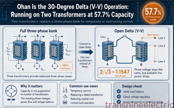
One argument that gets mixed into this discussion needs separating out. The claim is that a delta bank can keep running with one winding out, at reduced capacity. That is true, and it is about an open delta connection, which delivers 57.7 percent of the bank’s rated capacity, not about grounding at all. It is a property of the winding arrangement and it applies to a delta secondary whether it is grounded or not.
Losing a winding is not a ground fault. The two advantages get bundled together in older training material because both were sold as continuity features, and they are not the same mechanism.
The restrike overvoltage, which is what actually breaks things
If you only remember one technical argument from this page, make it this one, because it is the argument that survives every change in fashion.
The mechanism is a trapped DC offset
System capacitance holds charge. When a phase arcs to ground, the arc carries current until it extinguishes at a current zero, and at that moment the capacitance is left holding whatever voltage the phase was at.
If the fault stays open, nothing happens. If it restrikes, it usually restrikes at some random point on the next cycle, and the source may be at the opposite polarity from the trapped charge. The voltage across the gap is then the sum of the two, not the difference.
Nothing in the system limits it. There is no impedance in the loop to absorb the difference.
The peak phase-to-ground voltage at 277 volts nominal is 391.7 volts. A worst case first restrike puts twice that across the gap, 783 volts, which is 2.83 times the normal rms phase voltage.
| Condition | Phase-to-ground voltage | Multiple of normal rms |
|---|---|---|
| Normal peak | 392 V | 1.41 |
| One worst case restrike | 783 V | 2.83 |
| High-resistance grounded, about 2.5 times | 692 V | 2.50 |
| Sustained intermittent arcing, low end | 1,662 V | 6.0 |
| Sustained intermittent arcing, high end | 2,216 V | 8.0 |
Repeated restrikes keep adding charge, and the classic figure for a sustained intermittent arcing fault is six to eight times the normal phase voltage. At 277 volts nominal, that is 1,662 to 2,216 volts.
The coincidence that makes it concrete
The usual factory AC withstand test for a 480 volt motor is twice rated voltage plus 1,000, applied for one minute. For a 480 volt machine that is 1,960 volts.
The top of the restrike band is 2,216 volts. The worst case intermittent arcing fault on an ungrounded 480 volt system puts the winding above the voltage the factory used to prove it in the first place.
That is the mechanism behind the phone call that says the transformer failed for no reason after a ground fault that nobody could find. The insulation did not fail from the fault. It failed from what the system did to itself while the fault was there. The edition of the test standard and the product standard both vary, so check the nameplate and the edition your authority having jurisdiction has adopted, but the arithmetic is not close enough to be a rounding question.
Why a bigger system is worse, not better
It is tempting to assume that a larger plant with a larger transformer is built to take more abuse. On an ungrounded system it is the opposite.
A larger system has more capacitance, so the arc has more energy, so it restrikes more reliably, so it traps more charge. And a larger system also has more insulation to damage, spread over more equipment, in more places. The failure mode scales in the wrong direction.
This is the reason the engineering consensus moved. It was not a sudden belief that grounding is safer. It was the observation that the systems the ungrounded delta was designed for were small, and the systems people were building were not.
High-resistance grounding, and the sentence the brochures skip
High-resistance grounding is the modern answer for a plant that needs continuity. It is a genuinely good answer. It is also sold with a claim that is not true, and the claim matters because it is the one people use to justify keeping 277 volt rated equipment downstream.
Same voltage, different current
Connect a resistor between the wye point and ground, sized so that a bolted ground fault produces a small, known current. Five amps is the usual figure at 480 volts.
Now run the fault. The faulted phase goes to zero. The neutral point has to rise to 277 volts above ground, because that is the only way to drive five amps through the resistor. The two healthy phases therefore sit at 480 volts to ground, exactly as they would on an ungrounded delta.
The resistor does not hold the healthy phases at 277. It cannot. The voltage shift is set by the fault being bolted, and the resistor only decides how much current flows once the shift has happened.
| Ungrounded delta | High-resistance grounded wye | |
|---|---|---|
| Healthy phase to ground, normal | about 277 V | 277 V |
| Healthy phase to ground, during a fault | 480 V | 480 V |
| Fault current | 0.2 to 5 A, whatever the capacitance allows | 5 A, set by the resistor |
| Transient overvoltage on restrike | 6 to 8 times, up to 2,216 V | about 2.5 times, 692 V |
| Fault location | hard, no current to trace | a pulser can trace it |
| Continuous operation through a fault | yes, until something else fails | yes, by design |
So what does the resistor buy? Two things, and they are worth the money.
It kills the restrike overvoltage, because the resistor drains the trapped charge between restrikes. That takes the 6 to 8 times band down to about 2.5 times, which is the difference between exceeding a motor’s factory withstand and staying comfortably under it.
And it turns an unmeasurable fault into a measurable one. Five amps is a signal you can chase with a clamp, pulse, and locate. Two amps of capacitance spread across three phases is not.
What it does not buy is a lower voltage exposure. If your downstream gear is rated for 277 volts to ground, an HRG source will still put 480 across it during a fault. The varistors and the drive filters in section two do not care that the current is limited.
The resistor arithmetic
This is where a specification goes wrong in a way that shows up two years later.
Five amps at 277 volts needs 55.4 ohms. The power is current squared times resistance, so 25 times 55.4, which is 1,385 watts. Continuous.
| Fault current | Resistance | Continuous power |
|---|---|---|
| 2 A | 138.5 ohm | 554 W |
| 5 A | 55.4 ohm | 1,385 W |
| 10 A | 27.7 ohm | 2,770 W |
A 1.4 kilowatt heater in a steel enclosure is a real thermal design, not a catalog line item. It needs ventilation or a properly sized enclosure, and it needs to be rated for continuous duty.
Which brings up the purchase trap. Resistors are sold both continuous rated and short-time rated, commonly 10 seconds. A 10 second unit is much smaller and much cheaper, and it is the right choice on a system that trips on the first fault. On an HRG system, where the entire philosophy is that the plant keeps running while someone finds the fault, a 10 second resistor is a fuse with extra steps. If the fault sits for six hours, the resistor is the thing that fails.
The resistor sees 277 volts, not 480, because it is connected from the neutral to ground and the neutral only displaces by the phase voltage. Ordering a 480 volt rated resistor is money spent on nothing. The insulation from the resistor element to its enclosure still has to be 600 volt class.
The 1.4 kVA that everyone oversizes
If you use a zigzag grounding transformer instead of a neutral resistor, which is what you do on a delta system with no neutral point, the throughput is 277 volts times 5 amps, or 1,385 volt-amperes.
That is 1.4 kVA. Next to the 1,000 kVA transformer it is protecting, the number looks like a typo, and it is correct. Grounding transformers are ordered on a short-time rating, so a unit specified as 5 amps for 10 seconds is a small frame with a small price.
Two things to get right. First, do not size it like a distribution transformer, or you will buy ten times the machine you need. Second, match the time rating to the philosophy. If the plant intends to run through faults for a shift, the grounding transformer needs a continuous zero-sequence rating, not a 10 second one.
The arrester trap, again
Everything in section two applies here, with one addition. Converting a system to HRG is often sold as a way to keep existing equipment. That is true for the transformers, the switchgear, and the motors. It is not true for the surge arresters and the drive filters, because those were selected against the phase-to-ground voltage of the source, and the source did not change.
Check the MCOV on every arrester on the bus before you energize an HRG retrofit. If they are 275 or 320 volt units, they were correct for a solidly grounded system and they are wrong for this one.
The two ways to ground a delta without a neutral
If you own a delta secondary and you want a ground reference, there are two hardware answers besides adding a grounding transformer. Both are cheap. Both have a consequence that shows up on the equipment schedule.
Corner grounded, and the breaker you cannot use
Ground one corner of the delta. That conductor is at zero volts to ground permanently, and the other two sit at 480 volts to ground permanently, in normal operation, with nothing faulted.
That single fact eliminates a whole class of devices. A circuit breaker marked 480/277 is slash rated, which means 480 volts between poles and 277 volts from any pole to ground. On a corner-grounded system every pole sees 480 volts to ground, so the slash rating is not met and the breaker cannot be used. You need straight rated 480 volt or 600 volt breakers, and they cost more.
The rest of the list is bookkeeping that has to be done right.
- The grounded conductor has to be identified throughout the system, white or gray, and it is a current-carrying conductor in normal operation.
- No overcurrent device in the grounded conductor unless all poles open together, with the motor overload exception.
- The grounded phase has to be marked at every enclosure, because a conductor reading zero volts to ground looks de-energized to anyone who does not know.
- You cannot get 277 volts out of it, so lighting and receptacles need their own transformer anyway.
There is a reason corner grounding is described in every textbook as a historical solution. It solves the voltage stability problem at the lowest possible hardware cost and it hands the bill to everyone downstream.
High leg, and the 208 that is not a mistake
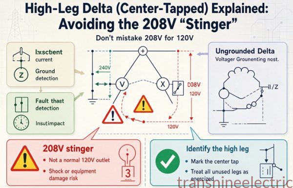
Center tap one winding of a 240 volt delta and you get 120/240 single-phase plus 240 three-phase from one transformer. The center tap becomes the neutral, and the phase opposite it sits at 208 volts to ground.
208 is 120 times 1.732. It is not a fault and it is not a miswinding. It is the line-to-line voltage of the two 120 volt halves, measured from the far corner.
Three consequences, all of them specified in the code and all of them missed on replacement jobs.
The high leg has to be the B phase, and it has to be marked orange, so that nobody lands a 120 volt circuit on it.
A 120/240 slash rated breaker cannot be used on the high leg, because that pole sees 208 volts to ground.
And the center tap is a physical feature of the winding. If you replace a high-leg transformer with a plain 240 volt delta, you lose every 120 volt load in the building. This is the single most common specification error in this whole subject, and it happens on emergency replacements where nobody reads the old nameplate carefully.
What the code actually requires, in five citations
Grounding arguments get settled by article numbers more often than by physics, so here are the ones that matter, and what each one actually says.
250.20(B) decides, and it is arithmetic
Systems in the 50 to 1,000 volt range that supply premises wiring must be grounded if any of three conditions holds: the system can be grounded so that the maximum voltage to ground is 150 volts or less; it is a three-phase four-wire wye with the neutral used as a circuit conductor; or it is a three-phase four-wire delta with the midpoint of one winding used as a circuit conductor.
A 480 volt three-wire delta cannot be grounded at 150 volts or less, because 480 divided by 1.732 is 277. It is not a wye with a neutral doing work. It has no midpoint used as a circuit conductor. So it is not on the list.
That is the entire legal basis for an ungrounded 480 volt delta. Not a philosophy. A division problem, and the answer is 277, and 277 is more than 150.
250.21(A), (B) and (C), the escape hatch and its two strings
250.21(A) lists the systems that are not required to be grounded, including industrial electric furnaces used for melting or refining, separately derived systems feeding rectifiers that supply only adjustable speed drives, certain control circuit transformers, and anything from the 250.20(B) list that the designer chose not to ground.
Then the code follows those systems around, and this is where people get caught.
250.21(B) requires ground detectors on the system, installed as close to the supply as practicable, so that the detector watches all three phases at once.
250.21(C) requires a caution sign, at the service and at each building or structure supplied, stating that the system is ungrounded and giving the voltage between conductors.
The sign is the requirement that never gets installed, and it is the first thing a good inspector looks for after confirming the detector works. It is also the only thing in the building that tells the next electrician what they are standing in front of.
250.30, the secondary is still a separately derived system
A transformer secondary is a separately derived system whether it is grounded or not. It needs a grounding electrode conductor, an equipment grounding conductor, and a supply-side bonding jumper.
What it does not need, if it is ungrounded, is a system bonding jumper, because there is no grounded conductor to bond. The field error runs the other way. A delta-wye unit with the neutral brought out and bonded at both the transformer and the first disconnecting means puts normal load current on the grounding electrode conductor and on every piece of metal in between. That is a real, measurable, and surprisingly common defect.
230.95 and 215.10, the 1,200 amp ceiling
Ground-fault protection is required on 480Y/277 services rated 1,000 amps and above, with the pickup set no higher than 1,200 amps. Feeders get the same treatment under 215.10 above 1,000 amps.
This is the citation that makes the ungrounded delta attractive in a retrofit, because it is the citation that puts the 0.231 ohm ceiling on the grounded system. A plant with a history of unexplained arcing failures on a 480Y/277 service is usually a plant with faults below that ceiling.
240.85, slash ratings
A circuit breaker with a slash rating can only be used where the voltage to ground does not exceed the lower of the two numbers. This is the citation behind the corner-grounded breaker problem, and it is the one that gets missed on a service replacement where the new switchboard arrives with slash rated main and the inspector finds it during the acceptance walk.
The part that costs money
If you are buying new
Write the secondary on the purchase order as one of two different machines, because that is what it is.
| What you write | What you get | What it forces downstream |
|---|---|---|
| 480Y/277, 4 wire, neutral brought out to a fully rated bushing, solidly grounded | a wye secondary with a neutral terminal | 4 wire feeder, service ground-fault protection above 1,000 A, 277 V available for lighting, slash rated breakers allowed |
| 480 delta, 3 wire, no neutral | a delta secondary with three terminals | 3 wire feeder, ground detector, 600 V rated gear to ground, separate transformer for 277 V or 120 V loads |
| 480 delta, 3 wire, one corner grounded | a delta secondary with a marked grounded phase | 3 wire feeder, straight rated breakers only, grounded conductor identified everywhere |
| 480Y/277 with a 5 A resistor, zigzag grounding transformer and pulsing controller | a wye secondary with an impedance grounded neutral | 4 wire or 3 wire, 59N relay, pulser, 600 V rated arresters, and someone trained to chase the fault |
The one thing you cannot do is buy a delta-delta and decide to ground it at the neutral later. There is no neutral terminal. The decision has to be made before the order, and this is the single most common reason a replacement transformer comes back.
If you already own the delta
Four paths. Ranked by what they fix, not by price, because the cheapest one fixes almost nothing.
| Path | Detects the fault | Kills the restrike transient | Keeps the plant running | Allows 277 V loads |
|---|---|---|---|---|
| Add a ground detector, 3 VTs and a 59N, or 3 lamps | yes | no | yes | no |
| Add high-resistance grounding, zigzag plus resistor plus controller | yes, and locatable | yes | yes | no |
| Corner ground one phase | yes, by tripping | yes | no | no |
| Replace with a grounded wye unit | yes | yes | no, it trips on the first fault | yes |
The first row is the one to do this quarter if the budget is zero. A ground detector is three voltage transformers and a relay, or three lamps and a panel, and it converts a system that tells you nothing into a system that tells you a fault exists. It does not fix the overvoltage and it does not help you find the feeder, but it stops the failure mode where a fault sits on the system for a year.
The second row is the one to do next year. It is the only path that keeps the plant running and removes the overvoltage mechanism at the same time.
The third row is cheap and I would not recommend it except as a temporary measure during a service rebuild, because it permanently puts 480 volts to ground on two phases and takes slash rated gear off the table.
The fourth row is the right answer if the building also needs 277 volt lighting, or if the load is not a continuous process. It is a project, not a retrofit.
The three questions to ask before you pick
- How much capacitance does the system actually have? Measure it. The charging current is 2 times pi times frequency times capacitance times phase voltage, and the capacitance is measurable with the system de-energized and a suitable instrument. The 1 to 2 amps per MVA figure is a placeholder, not a design input.
- What is downstream that is rated to 277 volts to ground? Arresters, drive filters, panel meters, pilot lamps, and any 480/277 slash rated device. This list decides whether the retrofit is a weekend or a shutdown.
- Who walks the plant with a five amp clamp when the detector says fault? If the answer is nobody, high-resistance grounding is a promise you cannot keep, and you should buy the grounded wye and spend the money on the ground-fault settings instead.
That third question is the one that separates a design from a document. An HRG system on a plant with no maintenance staff is a system that will run through its first fault, and then its second, and then fail.
The decision, in one table
| Situation | Answer | Why |
|---|---|---|
| New commercial building, mixed loads | 480Y/277 solidly grounded | 277 V lighting and 480 V motors from one transformer, and the code expects it |
| New industrial plant, continuous process | high-resistance grounded wye, 5 A, with pulsing | keeps running, kills the restrike transient, and the fault is locatable |
| Existing 480 delta under about 5 MVA, no electronics | ground detector now, HRG when the budget allows | the continuity claim is still true at that size |
| Existing 480 delta over about 5 MVA | HRG, and treat it as urgent | charging current already exceeds what a self-extinguishing arc can handle |
| Heavy VFD population | HRG, plus feeder ground-fault CTs, plus a filter review | the drives are the equipment most exposed to the 480 V shift |
| Healthcare occupancy | solidly grounded | the ground-fault path has to open, and the code does not leave room |
| Replacing a high-leg 240 delta | keep the center tap | otherwise every 120 V load in the building goes dark |
| Replacing a delta-delta with a wye unit | check the feeder and the switchboard first | you are adding a neutral, a bonding jumper, and possibly ground-fault protection |
FAQ
Is an ungrounded delta safer than a grounded wye?
No, and it is not less safe either, in the abstract. A person touching a live phase during a ground fault gets 480 volts on a delta and 277 on a grounded wye, and 277 volts through a body is already well past the current that stops a heart. What actually differs is how long the hazard exists. The grounded wye clears in cycles. The delta does not clear at all.
What is the voltage to ground on an ungrounded 480 volt delta?
During normal operation it floats near 277 volts, set by the capacitance of the cable and the equipment to ground, not by the winding. It is not a fixed value and it drifts as the system changes. When one phase faults to ground, that phase goes to zero and the other two rise to 480 volts.
Why does the first ground fault not trip an ungrounded system?
Because a delta winding has no neutral terminal, so zero-sequence current has no path out of the winding. The fault draws only the capacitive charging current of the system, which is a few amps at most. No overcurrent device responds to that, which is the whole point of the design and also its main problem.
What is the smallest ground fault a 480Y/277 ground-fault relay can see?
Divide the phase voltage by the pickup. At the 1,200 amp maximum pickup the code allows, 277 divided by 1,200 is 0.231 ohms. Any ground fault with more than a quarter of an ohm in the path cannot reach the pickup. At a 400 amp setting the ceiling is 0.693 ohms.
Can you ground a delta-delta transformer?
Not at a neutral, because there is no neutral terminal. You can ground one corner, which puts 480 volts to ground on the other two phases. You can add a center tap, which gives a high leg. Or you can add a zigzag grounding transformer to create an artificial neutral, which is what high-resistance grounding does.
Does high-resistance grounding lower the voltage to ground?
No. During a bolted ground fault the neutral has to displace by the full phase voltage to drive current through the resistor, so the two healthy phases still reach 480 volts to ground. What the resistor changes is the current and the restrike transient. It takes overvoltage from 6 to 8 times nominal down to about 2.5 times.
What size resistor do I need for 5 amps at 480 volts?
55.4 ohms, because 277 divided by 5 is 55.4. It dissipates 1,385 watts, continuously, which is a real thermal design rather than a catalog item. Order a continuous rated unit if the plant intends to run through faults, not a 10 second unit.
What causes the 6 to 8 times overvoltage on an ungrounded system?
A restriking arc trapping charge on the system capacitance. The arc extinguishes at a current zero with the capacitance charged, then restrikes when the source is at the opposite polarity, so the gap sees the sum of the two. Repeated restrikes keep adding charge. At 277 volts nominal, 6 to 8 times is 1,662 to 2,216 volts.
How do you detect a ground fault on an ungrounded system?
A voltage relay watching neutral displacement, usually a 59N on the broken delta of three voltage transformers, or three lamps connected phase to ground. The code requires ground detectors on these systems. A 59N set at 5 percent of nominal detects a fault with about 589 ohms in the path.
What does NEC 250.21(C) require?
A caution sign at the service and at each building or structure supplied, stating that the system is ungrounded and giving the voltage between conductors. It is the requirement that most often goes missing, and it is the only thing in the building that warns the next electrician what they are working on.
Can I use slash rated breakers on a corner-grounded delta?
No. A 480/277 slash rated breaker is good for 277 volts from any pole to ground, and on a corner-grounded system every pole sees 480 volts to ground during normal operation. Use straight rated 480 or 600 volt devices. The requirement is in 240.85.
What is the high leg voltage on a 240 volt delta?
208 volts to ground, because it is 120 times 1.732. The high leg has to be the B phase and it has to be marked orange, and no 120/240 slash rated breaker can be used on it. A high-leg service is a 240 volt three-phase service with a lighting tap, so replacing it with a plain 240 delta loses every 120 volt load.