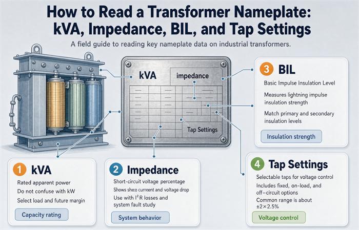
To read a transformer nameplate, check five fields in this order: the kVA rating (power capacity), primary and secondary voltages (system match), percent impedance %Z (fault current and voltage drop), BIL (lightning-surge withstand), and tap settings (turns-ratio adjustment). Together they tell you whether the unit will safely and legally fit your installation.
A nameplate is the one document a transformer wears for its whole life. It is stamped, etched, or riveted onto the tank or enclosure, so what it says is what the factory built. For a buyer, that makes it more useful than a brochure. The brochure sells. The nameplate tells the truth, and it is the baseline you use to compare two quotes that look identical on paper.
This guide is written for the person who has to specify, compare, or accept a transformer: a procurement engineer, an EPC estimator, a distributor, or a facility owner. We will read the plate the way you actually make decisions, not top to bottom like a random table. We will also flag the spots where a cheap unit and a compliant unit quietly diverge.
What a transformer nameplate really is
Think of the nameplate as the unit’s ID card and contract in one piece of metal. It carries the ratings the manufacturer tested the unit against. If the field wiring, the load, and the protection all line up with what is printed, the installation behaves. If they do not, the plate is also your first piece of evidence for why something failed.
Most plates group data into a few zones: identity (maker, serial, year), ratings (kVA, voltage, frequency), performance (impedance, BIL, taps, cooling), and physical data (weight, fluid, standards marks). Different makers lay these out differently. Do not worry about the layout. Worry about the numbers.
The single most useful habit is to read the plate in the same order you make accept or reject decisions. That order is below.
The five fields you read first
Here is the field order we use on site and in the bid room. It moves from “will it even fit the system” to “will it behave under fault.”
- kVA — how much load it can carry.
- Primary and secondary voltage — does it match your system.
- Percent impedance %Z — sets your fault current and breaker sizes.
- BIL — surge withstand, matters for outdoor and exposed sites.
- Tap settings — the turns-ratio adjustment, easy to get wrong after service.
After those five, you confirm frequency, cooling class, vector group, temperature rise, losses, and the standards marks. We will go deep on the first five because that is where most expensive mistakes start, then cover the rest in a compact section.
| Field | What it tells you | Red flag for a buyer |
|---|---|---|
| kVA | Continuous apparent-power capacity | A round “nice” number that is not a standard step |
| HV / LV voltage | Whether it fits your system | 50 Hz unit offered for a 60 Hz grid, or vice versa |
| %Z | Fault current and voltage drop | No %Z printed, or a value that breaks your breaker coordination |
| BIL | Lightning and switching surge withstand | Low BIL on an outdoor or coastal site |
| Taps | Ratio adjustment range | OLTC promised but plate shows off-circuit only |
kVA: how big is this transformer?
kVA is the rating everyone quotes first, and it is also the one most often misunderstood. It is apparent power, not real power. A transformer heats up because of voltage and current, not because of the load’s power factor. So the maker rates it in kVA, which ignores whether your load is resistive, inductive, or somewhere in between.
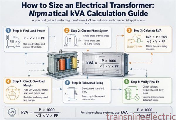
If your load is 800 kW at 0.9 power factor, the apparent load is about 889 kVA. You do not size the transformer at 800 kVA. You size it at the kVA your load actually draws, then leave headroom for growth.
Standard three-phase distribution steps run in a ladder: 15, 30, 45, 75, 112.5, 150, 225, 300, 500, 750, 1000, 1500, 2000, 2500 kVA and up. If a quote shows a kVA that is not on the ladder, ask why. It may be a special build with a longer lead time, or it may be a number someone rounded.
For a buyer, the kVA line is also where two quotes diverge in disguise. One supplier may quote a 1000 kVA unit, another a 1125 kVA unit, both “about a meg.” They are not the same unit, the same price, or the same footprint. Always compare on the exact standard step.
Impedance (%Z): the number that decides your breakers
Percent impedance is the value that surprises people. It is not a loss figure. It is the share of rated voltage you would have to apply to one winding to push full-load current through the other winding when it is shorted. In plain terms, it is how much the transformer resists a fault.
Lower %Z means the transformer holds voltage better under load, but it lets more fault current through. Higher %Z tames fault current but adds voltage drop. Both are true at the same time, which is why %Z is an engineering trade, not a “lower is better” spec.
You can estimate the available fault current at the secondary with one line:
Fault current ≈ Full-load current ÷ (%Z as a decimal)
That number drives the interrupting rating (AIC) of every breaker and fuse downstream. Ignore it and a downstream fault can exceed what your gear can break, which is how panels melt.
In the U.S., overcurrent protection for a transformer is sized per NEC 450.3(B). For a 480 V secondary, the primary protection is typically set at 125% of the primary full-load current, then rounded up to the next standard rating in NEC 240.6(A). A 1000 kVA unit lands at about 1600 A of primary protection. A 1500 kVA unit needs 2500 A, and a 2000 kVA unit needs 4000 A. If your upstream switchgear cannot host those ratings, the transformer will not fit the job even if the kVA looks right.
Two transformers with the same kVA but different %Z do not share load cleanly in parallel. For parallel operation, the %Z values need to be close, or one unit carries more than its share and runs hot.
BIL: will it survive a lightning strike?
BIL stands for Basic Impulse Level. It is the peak voltage the insulation can withstand from a lightning strike or a switching surge without breaking down. It is not the operating voltage. A 13.8 kV winding might carry 13,800 V all day but carry a BIL of 95 or 125 kV because that is what it must survive for a few microseconds.
BIL tracks the voltage class, not the individual unit. Typical reference values:
- Low-voltage winding (480 or 600 V): about 30 to 45 kV BIL
- 13.8 kV class: 95 or 125 kV BIL
- 25 kV class: 125 or 150 kV BIL
- 34.5 kV class: 150 or 200 kV BIL
These are typical ranges. The nameplate always controls. For a buyer, the practical question is exposure. A unit indoors in a clean switchroom faces little surge. A pad-mounted transformer on a long rural feeder, or a coastal site with frequent storms, needs BIL that matches that environment, and the surge arresters downstream must be coordinated to it. If a supplier quotes a low BIL to shave cost on an exposed site, that is a saving you will pay for later.
Tap settings: fine-tuning the ratio
Taps are adjustment points around the nominal primary voltage. They let the transformer correct for a system that runs a little high or a little low so the secondary stays near target. A common distribution arrangement is ±2 steps of 2.5%, giving five positions: +5%, +2.5%, 0, −2.5%, −5%.
There are two kinds. A de-energized tap changer (DETC) is set with the unit off. An on-load tap changer (OLTC) adjusts while energized, which matters for substations, data centers, and plants with drifting voltage. If your specification needs automatic voltage regulation, OLTC is not optional, and the plate (or the order spec) has to say so.
The quiet hazard is the tap position itself. A large share of “mystery low voltage” calls turn out to be a tap left on the wrong step after maintenance. Before energizing any unit that was serviced, confirm the tap position matches the system.
The supporting fields you cannot ignore
Once the big five check out, confirm the rest:
- Frequency: 60 Hz in North America, 50 Hz across most of Europe, Asia, and Australia. A 50 Hz transformer on a 60 Hz system runs a different flux and can overheat. Match it.
- Cooling class: ONAN (oil natural, air natural, no fans), ONAF (fans added), OFAF, ODAF. Dry-type units show AA or AN/AF. A dual-rated ONAN/ONAF unit has two capacities, and the higher one only counts when the cooling is actually running.
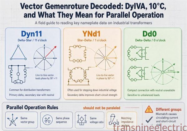
- Vector group: On three-phase units this is the connection and phase shift, shown as something like Dyn11 (delta primary, wye secondary with neutral, 30° shift). It decides grounding, harmonics, and whether two units can run parallel. IEEE and IEC use different labeling, so read the marker, not your assumption.
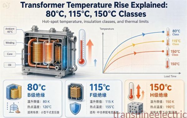
- Temperature rise: Often 55 °C or 65 °C for liquid-filled, or 80/115/150 °C rise classes for dry-type. It is the rise above ambient, not the absolute temperature.
- Losses: No-load and load loss. These drive life-cycle cost and, in the U.S., DOE efficiency compliance.
- Standards marks: Look for IEEE C57 (North America), IEC 60076 (international), and efficiency markings. U.S. distribution transformers fall under DOE 10 CFR 431, with updated efficiency levels taking effect in April 2029. EU units answer to the Ecodesign rules. Ask the supplier which standard the plate was built and tested to, because a unit built to one may not satisfy the other’s paperwork.
Worked example: reading one real nameplate
Let’s walk a realistic three-phase distribution transformer and turn the plate into decisions.
Nameplate reads: 1000 kVA, 3-phase, 60 Hz; Primary 13,200 V; Secondary 480Y/277 V; Impedance 5.75%; HV BIL 125 kV; LV BIL 30 kV; Taps ±2 × 2.5% (off-circuit); ONAN / ONAF.
Step 1, capacity
1000 kVA is a standard step, so it is a stockable, comparable unit, not a special.
Step 2, system match
Primary 13.2 kV and secondary 480Y/277 V are common North American distribution values. The “Y” with 277 V means a neutral is available for 277 V lighting and 480 V three-phase loads.
Step 3, secondary current
For three-phase: current = kVA × 1000 ÷ (√3 × line voltage). That is 1,000,000 ÷ (1.732 × 480) ≈ 1203 A at full load on the secondary.
Step 4, protection
Primary protection at 125% of primary full-load current, rounded to the next standard size, lands at 1600 A for this 1000 kVA unit. Your switchgear must accept that.
Step 5, fault current
1203 A ÷ 0.0575 ≈ 20,900 A, or about 20.9 kA at the secondary terminals. Your downstream breakers need an AIC rating above that, with margin for the upstream source.
Step 6, BIL and taps
125 kV BIL on the 13.2 kV winding is appropriate for the class. Five off-circuit taps let you trim ±5% if the incoming voltage runs off. There is no OLTC, so voltage regulation under varying load is manual only.
For a buyer, this one plate answered five questions: will it fit the system (yes), will my breakers hold (need 1600 A and >21 kA AIC), is the surge rating right (yes for the class), can I adjust ratio (manual ±5%), and is it a standard comparable unit (yes). That is the whole point of reading it well.
Buyer’s pre-purchase nameplate checklist
- kVA matches the load plus growth, and it is a standard step.
- Primary and secondary voltages match your one-line diagram.
- Frequency matches the local grid (50 or 60 Hz).
- %Z supports your fault-current study and breaker AIC ratings.
- BIL fits the site exposure, not just the minimum class.
- Tap type (DETC or OLTC) matches the voltage-regulation need.
- Cooling class supports the installation space and ambient.
- Vector group is compatible with existing or parallel units.
- Standards marked (IEEE C57 or IEC 60076) match your market.
- Supplier provides the factory test report and efficiency compliance documentation, not just the plate photo.
Number 10 is where import buyers get burned. The plate is what was built. The test report is proof it was built to that plate. Always ask for both.
Common mistakes buyers make
- Treating kVA as kW and undersizing the unit.
- Assuming 50 Hz and 60 Hz units are interchangeable.
- Skipping %Z and discovering the breakers cannot break the fault current.
- Buying on the lowest price without checking which standard the plate was tested to.
- Forgetting to confirm the tap position after the unit is serviced.
Frequently asked questions
What does kVA mean on a transformer nameplate?
kVA is the continuous apparent-power capacity the transformer can carry at rated voltage and frequency. It is not the same as kW because it does not account for power factor. Size the unit from your load’s kVA, not its kW.
What is %Z on a transformer nameplate?
%Z, or percent impedance, is the voltage needed to drive full-load current through a shorted winding, shown as a percent of rated voltage. It sets the available fault current and the voltage drop under load. Lower %Z means higher fault current and better regulation; higher %Z means the opposite.
What does BIL mean on a transformer nameplate?
BIL is the Basic Impulse Level, the peak surge voltage the insulation can survive from lightning or switching events, in kV. It tracks the voltage class (for example, about 95 to 125 kV BIL at the 13.8 kV class) and must be coordinated with surge arresters.
What are tap settings on a transformer nameplate?
Taps are fixed ratio-adjustment positions, commonly ±2 steps of 2.5% (five positions), that trim the output when the incoming voltage runs high or low. Off-circuit taps are set with the unit de-energized; on-load tap changers (OLTC) adjust while energized.
How do I calculate fault current from the nameplate?
Estimate secondary fault current as full-load current divided by %Z as a decimal. For a 1000 kVA, 480 V, 5.75% Z unit, full-load current is about 1203 A, so fault current is roughly 1203 ÷ 0.0575 ≈ 20.9 kA. Confirm with a full short-circuit study.
Does a 50 Hz transformer work on a 60 Hz system?
Not safely by assumption. Frequency changes the core flux and heating. A 50 Hz unit on a 60 Hz system runs a different flux density and can overheat. Match the nameplate frequency to the local grid.
Conclusion
Reading a transformer nameplate is less about memorizing definitions and more about asking the right five questions in the right order: capacity, system match, fault behavior, surge withstand, and ratio adjustment. Do that, and the plate stops being a wall of stamped text and becomes the tool that keeps your installation safe, your breakers sized, and your quotes comparable.