The transformer vector group is a nameplate code (like Dyn11, YNd1, or Dd0) that tells you how the windings are connected and by how many degrees the secondary voltage leads or lags the primary. It decides at a glance whether two units can safely run in parallel. Get the group wrong and the two transformers fight each other the moment you close the breaker, often before a single amp of real load flows.
This guide decodes the three groups in the headline, shows you exactly when they can and cannot share a busbar, and hands you a buyer’s checklist so the unit you order actually mates with the one already in the room.
What a Vector Group Actually Tells You
A vector group is a short string on the nameplate. It packs two facts into a few characters: the winding connections and the phase shift between the high-voltage (HV) and low-voltage (LV) sides.
Here is how to read it:
- The first capital letter is the HV winding. D means delta, Y means star (wye), Z means zigzag.
- The second lowercase letter is the LV winding. Same meanings: d, y, z.
- An N or n means the star point is brought out as an accessible neutral.
- The final number is a clock position. Each step on the clock equals 30 degrees of phase shift.
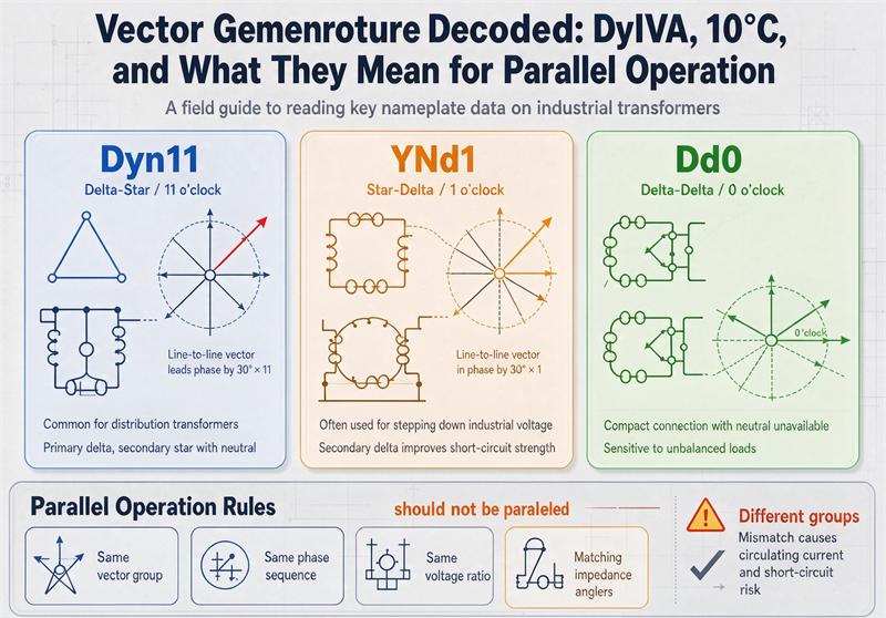
The clock trick is the part that trips people up. Picture the HV line-voltage vector pinned at 12 o’clock. The number tells you where the LV vector points. So Dyn11 means the LV sits at 11 o’clock, which is 30 degrees ahead of (leading) the HV. A 1 means 30 degrees behind (lagging). A 0 means the two are lined up.
That number is never random. Even numbers like 0 and 6 show up when both windings use the same connection type. Odd numbers like 1, 5, 7, and 11 appear when one side is delta and the other is star or zigzag.
Meet the Three Groups in the Headline
These three show up constantly in spec sheets and tender documents. They are not interchangeable, and the differences matter most the day you try to parallel them.
Dyn11: The Distribution Default
Dyn11 is a delta HV winding, a star LV winding with the neutral brought out, and an LV that leads the HV by 30 degrees. Walk into almost any European MV/LV substation and you will find it.
It earned that spot for three reasons:
- The delta HV traps triplen harmonics (the 3rd, 9th, 15th). Those currents circulate inside the closed delta instead of riding into the upstream grid, so your voltage stays clean.
- The star LV gives you a real neutral. That is what feeds single-phase 230 V loads alongside the three-phase 400 V, and it gives protection a defined earth reference.
- The delta keeps the LV neutral steady under unbalanced load. A lopsided mix of single-phase and three-phase loads will not drag the neutral voltage around.
That last point is why Dyn11 also shows a low zero-sequence impedance. A single-phase earth fault on the LV side pulls enough current for the relay to actually see it and trip.
YNd1: Generator Step-Up and HV Downstep (and Why It Is Not Dyn11)
YNd1 looks similar on paper but flips two things. The HV is star with a brought-out neutral, the LV is delta, and the LV lags the HV by 30 degrees.
You will see it on generator step-up units and on transmission or HV-to-MV substations. The star HV neutral is the important bit: it lets the utility earth the transmission winding solidly or through impedance, which the protection and fault-detection scheme depends on. The delta LV blocks zero-sequence current from the generator side.
Here is the buyer trap. People read “Dyn” and assume YNd1 is a cousin of Dyn11. It is not. Dyn11 has a delta on the high side; YNd1 has a star on the high side. The 11 versus 1 is not a typo, it is the opposite phase-shift direction (lead versus lag). Put the two on the same busbar and they will not parallel. More on that below.
Dd0: The No-Neutral Industrial Workhorse
Dd0 is delta on both sides with zero phase shift. No neutral comes out of either winding. That sounds like a limitation, and for distribution it is, but inside a plant it is exactly what you want.
Three-wire motor loads, furnace supplies, and welding buses do not need a neutral. The double delta blocks third harmonics and, with no neutral brought out, there is no path for earth-fault current to flow through the transformer. It is a compact, rugged choice for industrial feeds. You see less of it in new builds than Dyn11, but it is far from dead where the load is purely three-phase.
Quick Comparison
| Group | HV | LV | Neutral out | Shift | Where it shines |
| Dyn11 | Delta | Star + n | LV yes | +30° lead | MV/LV distribution |
| YNd1 | Star + n | Delta | HV yes | −30° lag | Generator step-up, HV to MV |
| Dd0 | Delta | Delta | none | 0° | Industrial motor loads |
Why Vector Groups Decide Parallel Operation
Parallel operation means two transformers feed the same busbar and split the load. For that to work without drama, four things have to line up:
- Same clock number. A Dyn11 and a Dyn5 cannot parallel unless you reconnect one.
- Same no-load voltage ratio, including the tap-changer position. Mismatched taps mean one unit back-feeds the other.
- Impedance voltages within roughly 10 percent of each other. Wide apart, and the lower-impedance unit grabs more than its share.
- Same phase sequence, verified at the terminals before you close the coupler.
The clock number is the deal-breaker. If two secondaries sit at different clock positions, there is a voltage difference between them the instant they meet. That difference drives a circulating current limited only by the two impedances.
You can estimate it. The voltage across the loop is roughly ΔV ≈ 2 × V × sin(Δθ / 2). For a 30 degree mismatch that is about 0.52 times the line voltage. On a 400 V system that is over 200 V pushing through a path whose impedance is only a few percent. With typical 5 to 6 percent impedances, the circulating current blows past full-load current in milliseconds. Best case the protection trips. Worst case the windings cook.
A 60 degree mismatch (Dyn11 next to Dyn1) is worse still. And note the quieter failure: impedance mismatch does not spark a short, but the lower-Z unit overloads while the pair never delivers its combined rating. You paid for two transformers and got the capacity of one and a half.
Can These Three Run Together?
This is the table buyers actually bookmark. Same group parallels cleanly. Mixing the three in the headline does not.
| Pair | Parallel? | What it takes |
| Dyn11 + Dyn11 | Yes | The standard case |
| YNd1 + YNd1 | Yes | The standard case |
| Dd0 + Dd0 | Yes | The standard case |
| Dyn11 + YNd1 | No | Opposite shift and different winding types; a phase swap will not fix it |
| Dyn11 + Dd0 | No | 30° shift plus connection mismatch; not correctable by swapping phases |
| YNd1 + Dd0 | No | 30° shift mismatch |
One subtlety worth calling out: Dyn11 and YNd1 share the same 30 degree magnitude but point in opposite directions, and their winding types differ. You cannot rescue that pairing by swapping two line connections. You would need a replacement or an interposing (phase-shifting) transformer, or you keep the two on separate busbars.
Fixing a Mismatch Without Replacing the Transformer
Some mismatches are fixable in the field or shop. If the two units differ only by clock position and share connection types, you can often reconcile them by reversing two phase connections on one unit. Dyn1 pairs with Dyn11 that way, and Dyn5 does too. A Yy0 can meet a Yy6 by reversing all three phases.
The headline trio is less forgiving. Dyn11 against YNd1 or Dd0 fails on two counts at once: wrong shift and wrong winding type. Swapping phases will not close that gap. Your realistic options are replace the new unit to match, add an interposing transformer, or run them on separate busbars with no tie.
A few larger units allow reconnection through terminal links in the compartment. Treat that as engineering work, not a field tweak. It changes the ratio and the nameplate has to be updated to match. Never assume a unit is reconfigurable until the manufacturer confirms it in writing.
A Buyer’s Parallel-Operation Checklist
If you are ordering a second or standby unit to parallel with one already installed, do this before you send the RFQ:
- Photograph the existing nameplate. Copy the vector group, voltage ratio, impedance, and tap position exactly. Do not round.
- Confirm the phase sequence (A-B-C) at the terminals with a meter, not from memory.
- Ask the supplier for a vector-group test report from factory acceptance (FAT), not just a stamped nameplate. A mislabeled plate is exactly how parallel failures happen.
- State the real system voltage and 50 or 60 Hz in the inquiry. The nominal label on the drawing is not the voltage at your site.
- If the old plate is unreadable, have the ratio and phase relation measured. Assume nothing.
What to write in the RFQ so parallel operation is guaranteed: “Unit must parallel with existing [model] having vector group [X], ratio [Y], impedance [Z%], tap at [position]. Provide vector-group verification per IEC 60076-1 / IEEE C57.12.90.” That one line saves a site visit and a burnt transformer.
Standards and Compliance
The vector group is defined in IEC 60076-1 (see Clause 3.10.7) and verified by the test methods in IEC 60076-1 and IEEE C57.12.90 for North American practice. It is a design-fixed nameplate item. Once built, it is not a setting you change from the HMI.
For procurement, the credible signals are the standard references and a test report, not a marketing claim. Ask for the FAT vector-group confirmation and the type-test certificates. If a vendor cannot show them, that is your answer.
FAQ
What does the number in Dyn11 mean? The number is a clock position. Each step equals 30 degrees of phase shift between HV and LV line voltages. In Dyn11 the LV leads the HV by 30 degrees (it sits at 11 o’clock against the HV at 12).
Can Dyn11 and YNd1 run in parallel? No. They share a 30 degree shift magnitude but in opposite directions, and their winding types differ (delta HV versus star HV). A phase swap will not fix it. Use matching groups or separate busbars.
Can Dyn11 and Dd0 run in parallel? No. Dd0 has zero phase shift and delta on both sides, while Dyn11 leads by 30 degrees with a star LV. The 30 degree mismatch drives a large circulating current the moment they connect.
What happens if you parallel transformers with different vector groups? A voltage difference appears across the secondaries and drives a circulating current limited only by the impedances. With typical 5 to 6 percent impedances this exceeds full-load current almost instantly. Protection trips at best; windings fail at worst.
How do I find out my transformer’s vector group? Read the nameplate first. Then confirm it with a factory or site vector-group test (FAT or SAT) using a phase-angle meter or an automatic test set. Never trust a hand-written label alone.
Can a vector group be changed after manufacture? Sometimes. Units with reconfigurable terminal links can be reconnected in the shop, which is engineering work and requires a nameplate update. Many designs are fixed. Confirm reconfigurability with the manufacturer before you rely on it.
Which vector group is best for distribution? Dyn11. The delta HV suppresses triplen harmonics, the star LV gives a usable neutral, and the low zero-sequence impedance makes earth faults detectable. It is the European MV/LV default.
Do the two transformers need the same impedance to parallel? They need to be close, within about 10 percent. Beyond that the lower-impedance unit carries more than its share and the pair never reaches its combined rating.