- Voltage: 10 / 35 kV
- Transformer: up to 2500 kVA
- Structure: HV + transformer + LV in one bay
- Standard: IEC 62271
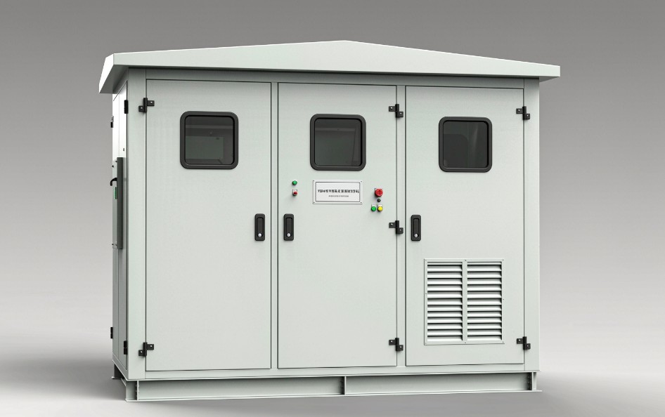
The YBW Series Prefabricated Compact Substation is a fully integrated, factory-assembled power distribution solution that consolidates medium-voltage switchgear, a distribution transformer, and low-voltage distribution panelboards into a single weatherproof enclosure. Designed for outdoor installation, the YBW Series eliminates the need for conventional substation buildings, fencing, and extensive site construction.
Each unit is pre-tested and pre-commissioned at the factory before shipment, enabling rapid on-site energization with minimal field labor. The YBW Series is engineered to meet the demands of U.S. utilities, real estate developers, and EPC contractors seeking a compact, reliable, and code-compliant alternative to traditional pad-mounted or vault-style substation configurations.
Key Applications
| Sector | Typical Use Cases |
|---|---|
| Electric Utilities | Distribution feeder tie-points, loop-feed sectionalizing, capacity upgrades in constrained rights-of-way |
| Real Estate Development | Residential subdivisions, mixed-use campuses, high-rise building services, parking structure power |
| EPC Contractors | Design-build power delivery packages, fast-track construction schedules, temporary-to-permanent power |
| Industrial & Commercial | Manufacturing plants, data centers, retail centers, healthcare campuses, educational facilities |
| Renewable Energy | Solar and wind farm collector substations, battery energy storage interconnections |
Standards Compliance and Certifications
The YBW Series is designed and manufactured to comply with applicable North American standards. Compliance documentation and third-party listings are available for each configuration. Key standards include:
| Standard | Scope |
|---|---|
| ANSI/IEEE C57.12.00 | General requirements for liquid-immersed distribution, power, and regulating transformers |
| ANSI/IEEE C57.12.34 | Requirements for pad-mounted, compartmental-type, self-cooled, three-phase distribution transformers |
| ANSI/IEEE C57.12.28 | Standard for tamper-resistant enclosure security requirements |
| UL 891 | Low-voltage switchboards rated 1000 V or less |
| UL 67 | Panelboards |
| UL 506 | Specialty transformers (where applicable) |
| DOE 10 CFR 431 | Energy efficiency requirements for distribution transformers (Tier 2 effective 2027) |
| NEC (NFPA 70) | National Electrical Code requirements for installation, grounding, and clearances |
| NEMA 3R | Enclosure rating for outdoor, rain, sleet, and snow protection |
Technical Specifications
Electrical Ratings
| Parameter | Specification |
|---|---|
| Rated High Voltage | 12.47 kV, 13.8 kV, 24.94 kV, 34.5 kV (common U.S. distribution classes) |
| Rated Low Voltage | 208Y/120 V, 480Y/277 V, 600Y/347 V |
| Transformer Capacity Range | 300 kVA to 3,000 kVA |
| High-Voltage Switchgear | Vacuum fault interrupters (VFI) or SF₆ load-break switches, dead-front construction |
| Low-Voltage Switchboard | Main breaker rating up to 3,000 A; UL 891 listed |
| Short-Circuit Withstand | Up to 25 kA symmetrical (typical); higher ratings available |
| Frequency | 60 Hz |
Physical and Environmental
| Parameter | Specification |
|---|---|
| Enclosure Type | NEMA 3R; tamper-resistant, weatherproof |
| Enclosure Material | Marine-grade aluminum or stainless steel; powder-coated for corrosion resistance |
| Protection Rating | IP54 or IP56 (dust and water ingress) |
| Ambient Temperature | −40 °C to +50 °C (design basis) |
| Sound Level | ≤55 dB at 1 m (configuration-dependent) |
| Enclosure Security | Meets ANSI/IEEE C57.12.28 tamper-resistant requirements |
| Finish | ANSI 61 gray or customer-specified color |
Design Features
Compartmentalized Construction
The YBW Series is divided into three primary functional compartments, each independently accessible and safety-interlocked:
High-Voltage Compartment — Houses the incoming primary terminations, load-break switches or vacuum fault interrupters, and high-voltage metering equipment. Dead-front elbow connections eliminate exposed live parts. Loop-feed configurations with six bushings and three-position (On/Off/Ground) switches are available for sectionalizing capability.
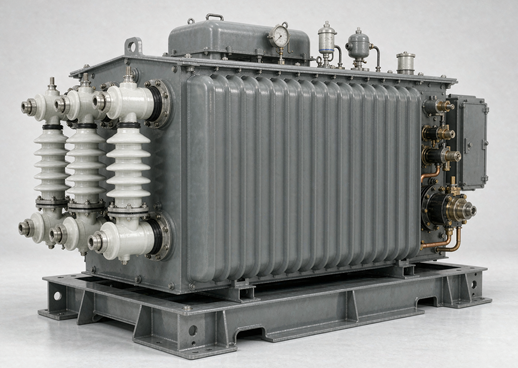
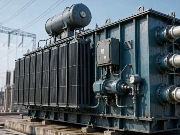
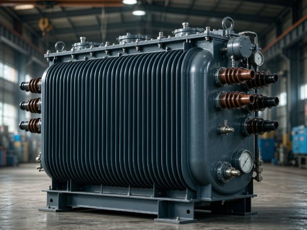
Transformer Compartment — Contains the core and coil assembly in a sealed tank (liquid-immersed) or dry-type encapsulated windings. Oil-immersed units utilize high-fire-point dielectric fluid. Ventilation louvers with thermostatically controlled fans ensure adequate cooling under full load.
Low-Voltage Compartment — Accommodates the main distribution switchboard, feeder breakers, branch panelboards, metering, and control wiring. UL 891-listed switchboard construction ensures compliance with NEC requirements for service-entrance and main-distribution applications.
Factory Pre-Testing and Pre-Commissioning
Every YBW Series unit undergoes a comprehensive factory acceptance test (FAT) protocol before shipment:
-
Routine Electrical Tests — Applied voltage withstand, induced voltage, insulation resistance, power factor (for liquid-filled transformers), and winding resistance.
-
Functional Verification — Switchgear operation, interlock function, ground continuity, relay calibration, and control circuit operation.
-
Leak and Pressure Testing — For liquid-immersed transformer tanks.
-
Witness Testing — Available upon request for utility-grade procurement; ISO/IEC 17025-certified test reports provided.
This pre-testing regime minimizes field start-up time, reduces the risk of commissioning delays, and ensures that the unit arrives ready for energization.
Safety and Security
-
Tamper-Resistant Enclosure — Meets or exceeds ANSI/IEEE C57.12.28 security requirements, permitting installation in unsecured public areas without additional fencing-19.
-
Dead-Front Design — All high-voltage connections utilize insulated elbows and bushings; no exposed live parts accessible during normal operation.
-
Interlocked Compartments — Mechanical interlocks prevent opening the high-voltage compartment while energized and prevent operation of switches with doors open.
-
Grounding Provisions — Copper ground bus with provisions for connection to station ground grid; ground rods and bonding per NEC Article 250.
Installation and Site Requirements
Pad and Clearance Requirements
The YBW Series requires a level, reinforced concrete pad (or engineered composite pad) with adequate load-bearing capacity for the unit’s weight. Typical utility clearance requirements for pad-mounted equipment:
-
Front Working Clearance: 6 feet minimum (for safe operation and maintenance access)
-
Side and Rear Clearance: 3 feet minimum
-
Above-Grade Working Space: Per NEC Article 110.26 for low-voltage compartment access
Note: Local utility requirements may exceed these minimums. Always verify with the authority having jurisdiction (AHJ) and the serving utility before finalizing site layout-5-16.
Conduit and Cable Terminations
The YBW Series accommodates both radial and loop-feed primary configurations. Primary terminations are typically dead-front separable connector interfaces compatible with industry-standard elbows (200 A or 600 A). A spare conduit stub-up extending 5 feet from the pad is recommended for future high-voltage access-9.
Secondary conductors exit through the low-voltage compartment via bottom entry. Conduit burial depth, fill percentages, and ampacity derating must comply with NEC Sections 300.5, Chapter 9 Tables, and 310.15-11.
Site Preparation Considerations
-
Soil Conditions: For frost-susceptible areas, conduit penetration through the pad must accommodate frost heave using expansion fittings or flexible conduit sections.
-
Drainage: Pad elevation should be set to prevent water accumulation at the compartment doors.
-
Access: Knuckle-boom crane access required for transformer replacement; verify approach clearances during site planning.
Frequently Asked Questions
Q1: What is the difference between a YBW prefabricated compact substation and a conventional pad-mounted transformer?
A: A conventional three-phase pad-mounted transformer contains only the transformer and a limited primary switching provision (typically an internal load-break switch). It requires a separate low-voltage switchboard or panelboard installation, usually inside the building being served or in a separate enclosure.
The YBW Series integrates the high-voltage switchgear, transformer, and low-voltage distribution panelboard into a single enclosure. This consolidated approach offers:
-
Single-Point Responsibility — One factory-tested assembly rather than multiple field-assembled components
-
Reduced Footprint — Up to 75% less land area than a conventional substation-8
-
Faster Commissioning — Factory pre-testing eliminates most field wiring and functional testing
-
Simplified Specification — One purchase order covers the complete power delivery package
Q2: Is the YBW Series compliant with U.S. electrical codes and standards?
A: Yes. The YBW Series is designed and manufactured to comply with the standards listed in the Standards Compliance section above. Specific compliance documentation, including UL listings (UL 891 for low-voltage switchboards, UL 67 for panelboards, UL 506 for transformers where applicable), ANSI/IEEE C57 documentation, and DOE efficiency certifications, is provided with each quotation and shipment.
For utility procurement, witnessed factory acceptance testing with ISO/IEC 17025-certified reports is available to satisfy utility-grade verification requirements-3-14.
Q3: What primary voltage classes and transformer capacities are available?
A: The YBW Series is offered in the following common configurations:
| Primary Voltage | Typical Secondary | Transformer Capacity |
|---|---|---|
| 12.47 kV | 208Y/120 V, 480Y/277 V | 300 kVA – 2,500 kVA |
| 13.8 kV | 208Y/120 V, 480Y/277 V | 300 kVA – 2,500 kVA |
| 24.94 kV | 480Y/277 V, 600Y/347 V | 500 kVA – 3,000 kVA |
| 34.5 kV | 480Y/277 V, 600Y/347 V | 1,000 kVA – 3,000 kVA |
Custom voltage and capacity combinations are available. Contact the factory for availability.
Q4: How long does installation take compared to a traditional substation?
A: The YBW Series dramatically compresses the construction schedule. Key time savings:
| Phase | Conventional Substation | YBW Series |
|---|---|---|
| Site preparation | 4–8 weeks | 1–2 weeks |
| Equipment installation | 2–4 weeks | 1–2 days (set on pad) |
| Field wiring and connections | 3–6 weeks | 3–5 days |
| Testing and commissioning | 2–4 weeks | 1–2 days (verification only) |
| Total typical duration | 12–22 weeks | 2–4 weeks |
The YBW Series requires only a prepared pad, conduit terminations, and final connections. Because the unit is factory pre-tested, field commissioning is limited to verification of external connections and functional checks-2.
Q5: What maintenance requirements does the YBW Series have?
A: Maintenance requirements are comparable to a conventional pad-mounted transformer plus switchboard installation:
-
Visual Inspection — Semi-annual inspection of enclosure integrity, ventilation openings, and security features
-
Transformer Fluid Testing — Annual dissolved gas analysis (DGA) and dielectric strength testing for liquid-immersed units (per IEEE C57.106 guidelines)
-
Switchgear Exercise — Annual operation of load-break switches or vacuum interrupters
-
Low-Voltage Inspection — Periodic thermographic survey of bus connections and breaker terminations
-
Ventilation System — Inspection and cleaning of thermostatically controlled fans and intake filters
Because the YBW Series is a sealed, tamper-resistant assembly, internal maintenance is performed by qualified utility or electrical service personnel only. Service access is available through the compartment doors with appropriate PPE and lockout/tagout procedures.
Q6: Can the YBW Series be configured for loop-feed distribution?
A: Yes. The YBW Series supports both radial and loop-feed primary configurations. Loop-feed units are equipped with:
-
Six primary bushings (two per phase, plus ground provisions)
-
Two-position or three-position load-break switches (On/Off, or On/Off/Ground)
-
Bushing-mounted elbow-type surge arresters at radial ends and normally open loop points
Three-position switches permit closed-transition loop feed and sectionalizing, allowing the unit to be isolated without interrupting service to downstream loads-9.
Q7: What documentation is provided with the YBW Series?
A: Standard documentation package includes:
-
Certified Test Reports — Routine electrical test results, functional verification records
-
Compliance Certificates — UL listings, ANSI/IEEE compliance declarations, DOE efficiency documentation
-
Outline Drawings — Dimensioned elevation, plan view, and pad details
-
Electrical Schematics — Single-line diagram, control wiring diagrams, interconnection diagrams
-
Installation Manual — Site preparation, setting instructions, connection procedures, torque specifications
-
Operation and Maintenance Manual — Operating procedures, maintenance schedules, troubleshooting guide
-
Recommended Spare Parts List — One-year operating spares with current pricing
Additional documentation (witness test reports, seismic certifications, arc-flash studies) available upon request.