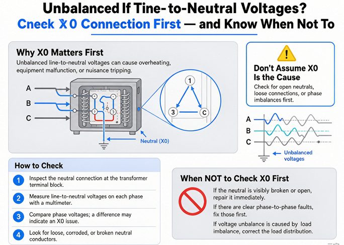
If your meter shows 135 V on one phase-to-neutral leg and 330 V on another while line-to-line reads a clean 208 V, you don’t have a bad transformer. You have a floating neutral. This guide walks through why X0 is the first thing to check, how to verify it with a meter, the right way to bond it, the situations where bonding X0 actually makes things worse, and — for buyers — how to specify the X0 terminal so the problem never reaches your floor.
What “Unbalanced Line-to-Neutral Voltage” Really Means
On a wye secondary, each phase-to-neutral (L-N) voltage should equal line-to-line divided by the square root of three. That math gives you the numbers you already know:
- 208Y/120 V → L-N ≈ 120 V
- 480Y/277 V → L-N ≈ 277 V
- 400Y/230 V (IEC) → L-N ≈ 230 V
Within a healthy system, L-N stays within roughly 1 to 3 percent of those values. The moment L-N starts drifting under load, watch the line-to-line reading. If L-L stays balanced while L-N spreads apart, that separation is the fingerprint of a neutral reference problem, not a winding fault. A damaged winding shows up on both.
Why X0 Is the First Place to Look
The floating-neutral mechanism
X0 is the secondary neutral point — the common connection of the three windings in a wye secondary. If X0 isn’t bonded to a grounding electrode, the neutral has no fixed reference. It floats, pulled around by capacitive coupling to the grounded tank, conduit and building steel, and shoved further by any load imbalance. The result is exactly what trips people up: line-to-line holds steady, but each phase-to-neutral leg reads something different.
What it looks like in the field (real numbers)
On a 112.5 kVA delta-wye unit (480 V primary to 208 V secondary), one facility measured these phase-to-ground voltages while the line-to-line stayed at 208 V:
| Leg (to ground) | Before X0 bond | After X0 bond | Expected |
|---|---|---|---|
| W | 135 V | 120 V | 120 V |
| Y | 237 V | 120 V | 120 V |
| E | 330 V | 120 V | 120 V |
| Line-to-line | 208 V | 208 V | 208 V |
A sister 60 kVA unit on the same line read a clean 120 V on all three legs the moment its X0 was properly tied — because that unit shipped with X0 already bonded to the tank. The takeaway is simple: without a bonded neutral, your L-N and L-G numbers are measuring against a moving reference. They tell you the neutral is floating, not that the line side has failed.
How to Check Your X0 Connection (Without Guessing)
Always start de-energized, verify zero voltage, and follow LOTO per OSHA 1910.333 and NFPA 70E. Then:
- Find X0 on the nameplate winding diagram. Don’t trust terminal position. Confirm X0 from the diagram before you touch anything.
- Check the bonding strap. Look for continuity between X0 and the enclosure ground bus or grounding pad. Is the strap present, seated, and tight?
- Measure X0-to-ground resistance with the source isolated. A solid bond reads under 1 ohm.
- Re-energize and measure each L-N at the panel. You want 120 V ±3 percent (or 277 V, or 230 V per system) with less than 3 V spread between legs.
- Check neutral-to-ground voltage at X0. Zero to 2 V is healthy. Above 2 V under load points to a loose or high-resistance bond or an undersized neutral. Up to 5 V can just be common-mode noise from VFDs and switching supplies.
The Fix — Bonding X0, Done Right
For a separately derived system — the transformer secondary is the source and the neutral isn’t carried from upstream — NEC 250.30(A)(1) requires the neutral grounded at the source. In plain terms: bond X0 to the grounding electrode system with a system bonding jumper.
Sizing the X0 bond
Size the bonding jumper per NEC 250.122 and the grounding electrode conductor per 250.66 (based on the largest ungrounded conductor). As a field quick-reference:
| Transformer | X0 bond (copper) | X0 bond (aluminum) |
|---|---|---|
| Up to 30 kVA | 10 AWG | 8 AWG |
| 45 to 150 kVA | 8 AWG | 6 AWG |
| 150 to 300 kVA | 6 AWG | 4 AWG |
| 300 to 500 kVA | 4 AWG | 2 AWG |
The single-point rule. Bond X0 at one location only. A second bond downstream — at a subpanel or another enclosure — creates a parallel neutral path and pushes objectionable current onto grounding conductors and raceways (NEC 250.6). Use a solid bond: no resistor, GFCI, or arc-fault device in the X0 path. Done right, L-N reads 115 to 125 V on a 120 V system with under 3 V spread between legs.
When Bonding X0 Is the WRONG Fix
This is the part most articles get wrong. The generic advice “just bond X0 to ground” is incomplete, and in two common situations it makes things worse.
Autotransformers
If you’re using an autotransformer with neutral terminals (H0/X0) and the upstream source transformer already grounds the neutral, grounding the autotransformer’s X0 creates a second ground at a different potential. Current circulates between the two grounds through the low-impedance autotransformer winding — enough to overheat and burn out coils. Hammond Power Solutions explicitly warns against locally grounding X0 on these units, and North American codes prohibit the multiple-ground situation.
Reverse-fed and non-derived systems
If the neutral is already bonded upstream — a utility neutral, or a continuous neutral run into the building — adding an X0-to-ground bond at the transformer ties two neutral references together. Small natural imbalances then drive current between the two X0 points through a conductor with no overcurrent protection. The field record on this is ugly: melted EMT, overheated transformers, and faults that vanish when you’re not looking. The fix is to leave X0 floating (or follow the design’s single designated bond point) and not add a second one.
Rule of thumb: Bond X0 only where the system is separately derived. If the neutral is already grounded upstream, do not add a local X0 ground.
Specifying X0 at Order Time
If you buy transformers, the cheapest place to solve this is on the purchase order, not on the floor at 2 a.m. Tell your manufacturer three things: your primary voltage, whether a neutral is brought in from upstream, and your local earthing system. Then pick the X0 termination style.
Three X0 termination styles
- Factory-bonded to tank. Solidly grounded wye, the default for North American 480Y/277 and 208Y/120 service transformers.
- Removable ground strap. An X0 bushing with a strap-to-grounding-pad link. You decide solid versus resistance grounding in the field. Common on pad-mounted units.
- Fully insulated X0 bushing, no bond. For systems where the neutral is grounded elsewhere, or for impedance- and high-resistance-grounded designs.
X0 and European earthing systems (IEC 60364)
The earthing system decides the terminal, so name it on the order:
- TN-S → separate N and PE brought out, single neutral bond at the transformer.
- TN-C-S → a combined PEN conductor splits into N and PE at the entry point.
- TT → local earth electrode plus an RCD; the transformer neutral may stay insulated.
- HRG / IT → high-resistance grounding limits fault current to 5 to 10 A for process continuity; X0 gets a neutral grounding resistor, not a solid bond.
Ask for the winding and connection diagram and the routine-test record showing the X0 circuit was verified. A nameplate that marks X0 clearly and states bonded or insulated will save you a service call.
Ordering tip: When you request a quote, send us your primary voltage, whether a neutral is brought in, and your earthing system (TN-S, TN-C-S, TT, or HRG). We’ll pre-wire X0 the right way and ship with the connection diagram.
Quick Reference — Cause, Symptom, Fix
| Symptom | Likely cause | What to do |
|---|---|---|
| L-N drifts, L-L stays balanced | Floating or unbonded X0 | Bond X0 to the grounding electrode system at one point |
| One L-N leg reads ~0 V, corrects after connection | X0 not landed or open link | Seat the X0 bonding strap, torque to spec |
| L-N imbalance only under unbalanced load, clears with motors running | High-resistance neutral or loose lug | Torque-check X0 and neutral lugs; verify N-G under 2 V |
| Burning smell or melted conduit near X0, no trip | Second X0 bond (multiple ground) | Remove the downstream bond; keep a single point |
| L-N unstable on an autotransformer after local X0 ground | Two grounds at different potential | Remove local X0 ground; rely on upstream neutral |
Frequently Asked Questions
What causes unbalanced line-to-neutral voltages?
On a wye (star) secondary, the usual cause is a floating or improperly bonded X0 neutral. Without a solid ground reference at X0, phase-to-neutral readings drift under load while line-to-line voltage stays balanced.
How do I know if my transformer neutral is floating?
Measure each phase-to-neutral and phase-to-ground voltage. If line-to-line is balanced (for example a clean 208 V) but the line-to-neutral legs read wildly different values such as 135 V, 237 V and 330 V, the neutral is floating. After bonding X0, all three should read within about 3 V of each other.
Should X0 always be bonded to ground?
Not always. Bond X0 at one point on separately derived systems. If the neutral is already grounded upstream (such as autotransformers with neutral terminals, or reverse-fed and non-derived systems), adding a local X0 ground creates a second ground at a different potential, which circulates current and can overheat and damage the winding. Follow the single-bond rule.
What size bond do I need for X0?
Size the system bonding jumper per NEC 250.122 and the grounding electrode conductor per 250.66. As a rule of thumb: up to 30 kVA use 10 AWG copper, 45 to 150 kVA use 8 AWG copper, 150 to 300 kVA use 6 AWG copper, and 300 to 500 kVA use 4 AWG copper (aluminum one size larger).
What is the difference between X0 on a European versus a North American transformer?
North American 480Y/277 V and 208Y/120 V systems usually bond X0 solidly at the transformer. European IEC 60364 systems (TN-S, TN-C-S, TT, IT) may bond the neutral at a single point, split a PEN conductor at entry, use a local electrode with an RCD (TT), or apply high-resistance grounding (HRG). So X0 may be bonded, insulated, or fitted with a neutral grounding resistor depending on the specified earthing system.
Can a floating neutral damage equipment?
Yes. A floating X0 lets phase-to-neutral voltage swing well above the rated value, for example 330 V on a 120 V leg, which destroys electronics, overheats motors on the over-voltage leg, and can place full phase-to-phase voltage on equipment enclosures during a line-side fault.
The One Thing to Remember
The next time a panel shows unbalanced line-to-neutral voltages, resist the urge to blame the windings. Nine times out of ten the answer is sitting at one small terminal: X0. Confirm it’s bonded at a single point for your system type, size the bond right, and if you’re ordering new, tell your manufacturer exactly how the neutral should be terminated so the problem never reaches your floor. Get the X0 connection right, and balanced L-N voltages follow.