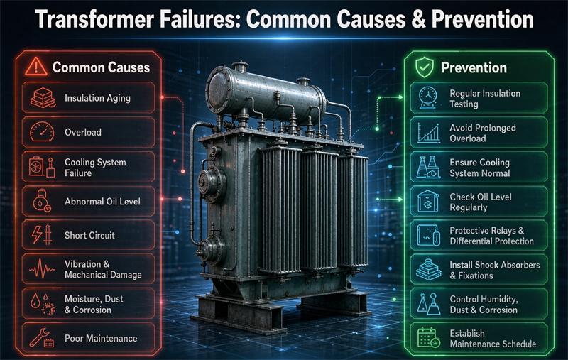
A transformer almost never fails for no reason. Most breakdowns trace back to a short list of preventable causes: insulation aging, overload and heat, moisture, oil degradation, partial discharge, tap-changer wear, short-circuit forces, and external surges. Each one has a clear prevention path, and most of them are caught long before they turn into a burnout.
At TransNine Electric we build distribution and power units for data centers, solar farms, hospitals, and utilities, so the failure modes below are what we design against every day. The goal of this guide is simple: help you understand why transformers fail, what the warning signs look like, and exactly what to write into a specification so you buy a unit that is hard to kill.
The eight common failure modes at a glance
| Failure mode | What actually happens | How often | How to prevent it |
|---|---|---|---|
| Insulation degradation | Paper, pressboard, and enamel lose dielectric strength, then clearances collapse into a short | Most common | Control temperature, keep oil dry, pick Class F or H insulation |
| Overload and overheating | Winding runs above design temperature, accelerating aging | Common | Size with a 1.1 to 1.25 margin, add temperature monitoring |
| Moisture and oil contamination | Water and particles cut dielectric strength in oil-filled units | Common | Sealed-tank design, breather maintenance, periodic oil testing |
| Partial discharge | Tiny sparks inside voids erode insulation until flashover | Common in older units | Request factory PD test per IEC 60270, keep oil clean |
| Tap-changer wear | On-load tap changer contacts wear, carbonize, and stick | Leading cause of downtime | Vacuum OLTC, limit needless operations, service the OLTC oil |
| Short-circuit forces | Fault current crushes windings through electromagnetic force | Less common but catastrophic | Specify short-circuit withstand per IEEE C57.12.90, set %Z for fault duty |
| External surges | Lightning or switching overvoltage punches through insulation | Less common | Rated surge arresters, proper grounding, coordination |
| Mechanical loosening | Vibration from transport or faults loosens clamps and windings | Less common | Transport locking, short-circuit strength testing |
The frequency column is a practical ranking from field experience and published reliability surveys, not a precise percentage. Insulation-related and thermal problems sit at the top of almost every study, which is why temperature and moisture control show up in nearly every prevention step below.
Why this matters before you buy
A single unplanned failure is rarely just the price of a new unit. For a hospital, data center, or utility feeder the real cost is downtime, emergency labor, and sometimes regulatory exposure. Published guidance and vendor field data put the total cost of one failure anywhere from tens of thousands to several million dollars depending on size and application. That spread is exactly why a procurement manager should treat “how do I keep it from failing” as a specification question, not just a maintenance question.
1. Insulation degradation is the number one cause
Insulation is the quiet part of a transformer, and it fails quietly too. The materials (kraft paper, pressboard, enamel, epoxy) age every hour the unit runs hot. The rule of thumb from IEEE C57.91 is blunt: every 8 to 10 degrees Celsius above the rated hot-spot temperature roughly doubles the aging rate. A unit designed for a 110 Celsius hot spot that routinely runs at 120 loses life about twice as fast.
Moisture and electrical stress make it worse. Water in oil or solid insulation lowers breakdown strength, and voltage surges open micro-voids that grow into failures.
How to prevent it
- Keep the winding hot-spot temperature inside the nameplate limit; IEEE C57.91 sets 110 Celsius for normal life and 120 Celsius for emergency loading.
- Specify Class F (155 Celsius) or Class H (180 Celsius) insulation for margin even on a Class A (105 Celsius) duty.
- Run dissolved gas analysis on oil-filled units so you see thermal faults forming.
- Request factory partial-discharge testing on critical units.
2. Overload and overheating
Overheating is the silent killer because it rarely trips anything on its own. A transformer loaded past its rating sheds heat slower than it makes it, the winding creeps hotter, and insulation ages ahead of schedule. Add poor ventilation, high ambient temperature, or harmonic currents and the margin disappears.
How to prevent it
- Size the unit for the actual load times a 1.1 to 1.25 margin rather than the peak estimate.
- Add winding-temperature indicators and alarms.
- Derate for altitude and high ambient per IEC 60076 guidance.
- Keep radiators, fans, and ventilation paths clean.
If you are laying out a data-center feed, our data-center calculator sizes the unit from IT load and redundancy so you do not end up under-rated.
3. Moisture ingress and oil contamination
In an oil-immersed transformer the oil does two jobs: it cools and it insulates. Let either job slip and the unit is in trouble. Water entering through a failed breather, oxidation building acid, or particles from an internal arc all cut dielectric strength.
Practical acceptance numbers from routine oil practice: dielectric strength above about 30 kV (ASTM D877/D1816), water content at or below about 10 ppm for power units, and acidity kept low. Dissolved gas analysis is the early-warning system: rising acetylene points at arcing, ethylene at overheating.
How to prevent it
- Use a sealed-tank or nitrogen-blanket design to keep moisture out.
- Maintain the breather and desiccant.
- Test oil on a schedule (dielectric strength, water, acidity, DGA).
- Regenerate or filter oil before it degrades the solid insulation.
4. Partial discharge
Partial discharge is the hidden precursor. Small sparks form in voids inside solid insulation or along contaminated surfaces, eroding the material a little at a time until a full flashover happens. You usually cannot see it, which is why testing matters.
The accepted factory check is a PD measurement per IEC 60270, with roughly 10 pC or less as a common acceptance level for new power transformers. Keeping oil dielectric strength above 30 kV and water below 10 ppm removes most of the conditions PD needs to start.
5. Tap-changer wear
The on-load tap changer (OLTC) is the most mechanical part of the machine, and mechanical parts wear. Contacts erode, lubricants slow, springs fatigue, and the OLTC oil carbonizes. Surveys of transformer unavailability consistently point at the OLTC as a leading cause of trips and outages even when the main windings are fine.
How to prevent it
- Specify a vacuum-type OLTC for frequent voltage adjustments.
- Service the OLTC oil on its own schedule.
- Limit unnecessary tap operations.
- Inspect contacts at planned intervals.
6. Short-circuit forces
This is the rare but catastrophic one. When a fault occurs downstream, the transformer sees a current many times its rating, and electromagnetic force scales with the square of that current. A 1000 kVA, 480 V unit with 5.75 percent impedance, for example, carries about 1203 A at full load but can see roughly 20.9 kA at the terminals during a bolted fault. The force at 20.9 kA is on the order of hundreds of times the force at 1.2 kA, because force grows with current squared.
That is why impedance is not just a protection number. Percent impedance (%Z) sets how high the fault current climbs, and IEEE C57.12.90 requires a short-circuit withstand test so the windings survive the mechanical beating. Specifying the right %Z for your system fault duty is part of buying a unit that will not be destroyed by the first downstream fault.
For a quick check of fault current and protection against your own system, our NEC sizing tool works through the numbers.
7. External surges
Lightning and switching events throw overvoltage transients down the line that can punch through insulation if the coordination is wrong. The defense is insulation coordination: the basic insulation level (BIL) of the winding, properly rated surge arresters, and a grounded neutral per local code. Typical BIL steps for distribution and power windings run 95, 125, and 200 kV, and the arrester rating has to sit below the BIL it protects.
8. Mechanical loosening
Vibration from road transport, repeated fault currents, or poor clamping can loosen core laminations and winding supports. Loose parts hum, wear insulation, and can short turns. The fixes are mostly design and handling discipline: proper transport blocking, pre-delivery vibration checks, and short-circuit strength testing so the frame stays put under fault forces.
A condition-monitoring schedule that catches failures early
You do not wait for smoke. The table below maps the common tests to what they reveal and a reasonable interval. Critical units (data centers, hospitals, substations) move to the shorter interval.
| Test | Reveals | Typical interval |
|---|---|---|
| Dissolved gas analysis (DGA) | Overheating, arcing, partial discharge | Annually; quarterly for critical units |
| Furan analysis | Paper insulation aging | Every 2 to 3 years |
| Power factor, tan delta | Moisture and contamination | Every 3 to 5 years |
| Infrared thermography | Loose connections, hot spots | Annually |
| Winding resistance | Loose connections, tap-changer wear | After fault events |
| SFRA, frequency response | Winding deformation | After short-circuit faults |
DGA and furan follow IEC 60599 and IEEE C57.104 for interpretation, while tan delta and PD reference IEC 60076 and IEC 60270. Treat the intervals as a starting point and tighten them for critical service.
Dry-type versus oil-immersed failure differences
The causes overlap, but the weak points differ. Dry-type units have no oil to contaminate, so moisture and oil-degradation failures simply do not apply. Their exposures are dust, blocked ventilation, and coil overheating, and a fire-risk conversation is mostly gone because there is no flammable liquid. Oil-immersed units cool better and handle higher loads, but they add the whole oil program: breather, leaks, BDV, DGA, and moisture. Both share insulation aging, PD, tap-changer wear, short-circuit forces, and surge exposure.
For a loss-and-lifetime view that feeds the prevention budget, our loss and TCO calculator turns efficiency losses into a 30-year cost you can plan around.
The buyer’s prevention checklist
This is the part most articles skip: turn prevention into specification language. When you issue a request for quotation, write these in.
- State the insulation class: Class F or H for margin even on a Class A duty.
- Require a factory partial-discharge test per IEC 60270 with an acceptance level around 10 pC for critical units.
- For oil-filled units, require sealed-tank construction and name the oil acceptance limits (BDV above 30 kV, water at or below 10 ppm).
- Specify the on-load tap changer type (vacuum OLTC) and the service interval.
- Set percent impedance for your system fault duty and require the IEEE C57.12.90 short-circuit withstand.
- Require basic insulation level (BIL) coordination with properly rated surge arresters.
- Ask for the routine-test report per IEEE C57.12.90 (or IEC 60076) before shipment.
- Name the condition-monitoring plan: DGA annually, infrared annually, tan delta every 3 to 5 years.
If you want to see how these choices look across a product line, browse the product range or read our transformer resources for the deeper standards guides. Real-world installs, from a hyperscale data center to a 50 MW solar plant, are in past projects.
Standards that govern reliability testing
- IEEE C57.91: loading guide and thermal aging, the 8 to 10 Celsius rule and hot-spot limits.
- IEEE C57.104 and IEC 60599: dissolved gas analysis interpretation.
- IEEE C57.12.90 and IEC 60076: routine tests, including the short-circuit withstand.
- IEC 60270: partial-discharge measurement.
- IEEE C57.12.00 / IEC 60076-1: general requirements and basic insulation level.
Wrapping up
Transformer failures are rarely random. They are the end of a chain that almost always starts with heat, moisture, or mechanical stress, and every link in that chain has a known prevention step. The practical takeaway for a buyer is twofold: run the monitoring schedule above, and write the prevention checklist into the specification so you start with a unit that is built to resist the eight common failure modes. Do both and the “unexpected” failure stops being unexpected.
FAQ
What are the most common causes of transformer failure? The leading causes are insulation degradation and overheating, followed by moisture and oil contamination, partial discharge, tap-changer wear, short-circuit forces, external surges, and mechanical loosening. Insulation and thermal problems top almost every reliability survey.
How does overheating cause transformer failure? Heat accelerates insulation aging. IEEE C57.91 states that every 8 to 10 degrees Celsius above the rated hot-spot temperature roughly doubles the aging rate, so a regularly overloaded winding loses life far faster than its nameplate suggests.
What does dissolved gas analysis detect? DGA measures gases dissolved in insulating oil. Rising acetylene indicates arcing, ethylene points to overheating, and hydrogen can signal partial discharge, giving early warning before a fault occurs. Interpretation follows IEEE C57.104 or IEC 60599.
Can a transformer fail without warning? Gradual failures like insulation aging or partial discharge build over months and show up in DGA, infrared, and tan delta tests long before they trip. Sudden failures are usually external, such as a downstream short circuit or a lightning surge.
How do you prevent transformer failure? Control temperature and moisture, specify Class F or H insulation, request factory partial-discharge testing, maintain oil, service the tap changer, set impedance for fault duty, fit surge arresters, and run the monitoring schedule in this guide.
Are dry-type transformers less likely to fail than oil-filled? Not necessarily, but they avoid oil-related failures such as contamination, leaks, and moisture in oil. Their main exposures are dust, blocked ventilation, and coil overheating. Oil-filled units cool better and handle higher loads but add the full oil-maintenance program.
What role does transformer impedance play in failure? Percent impedance sets the fault current magnitude during a downstream short circuit, because fault current equals rated current divided by percent impedance. Higher impedance lowers the fault current and the electromagnetic force that can crush windings, which is why IEEE C57.12.90 requires a short-circuit withstand test.
Which standards govern transformer reliability testing? Key references are IEEE C57.91 for loading and aging, IEEE C57.104 and IEC 60599 for DGA, IEEE C57.12.90 and IEC 60076 for routine and short-circuit tests, and IEC 60270 for partial discharge.