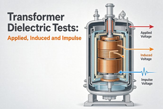
Transformer dielectric tests confirm that a transformer’s insulation can survive the over-voltages it will meet in real service, and the three you’ll see on every factory test report are the applied voltage test (a 60-second AC withstand from winding to ground), the induced voltage test (an over-voltage at twice rated, with the frequency raised so it stresses turn-to-turn insulation), and the impulse test (a simulated 1.2/50 µs lightning or switching surge).
If you buy or specify transformers, these three tests are the closest thing you have to a receipt for quality. Anyone can stamp a nameplate. These tests are the part where the insulation actually has to prove itself before the unit ever ships. This guide walks through what each test does, the numbers behind it, and — just as important — what to write into your specification so you actually get the proof you’re paying for.
What Dielectric Tests Actually Check
“Dielectric” is just the property of being a good electrical insulator. A dielectric test, then, is any test that pushes the insulation close to its limit to make sure it won’t break down.
In service, a transformer sees three kinds of over-voltage:
- Power-frequency over-voltages from switching, faults, and load rejection — handled by the applied and induced tests.
- Lightning surges arriving on the line — handled by the impulse test.
- Switching surges from breaker operations on higher-voltage systems — also an impulse-family test.
The reason buyers care is simple: insulation failure is one of the most common ways a transformer dies early, and it’s rarely cheap to fix. A clean dielectric test report is your evidence that the windings, leads, and bushings were built and assembled to take the hits.
One quick distinction worth keeping straight: applied and induced are routine tests (run on every unit), while the impulse test is a type test by default — run on a representative unit — though it becomes routine for higher-voltage units (more on that below).
The Applied Voltage Test — Winding to Ground
What it proves
The applied voltage test checks the main insulation: the barrier between a winding and everything else — the other windings, the core, the tank, and ground. All terminals of the winding under test are tied together and raised to a high AC voltage while everything else is grounded.
How it’s done
One winding is energized at power frequency (50 Hz or 60 Hz) for a set time, with all other windings and the tank connected to ground. If the insulation holds and the leakage current stays within limits, it passes.
The numbers
For liquid-immersed and dry-type units built to IEEE C57.12.90, the routine applied-voltage level is commonly twice the winding’s rated voltage plus 1,000 V, held for 60 seconds. IEC 60076-3 uses the applied voltage test (AV) mainly for windings with reduced (graded) insulation at the neutral end, with the level taken from the standard’s insulation table.
What it does NOT prove
This is the part newcomers miss. The applied test puts no voltage between turns of the same winding — all terminals are shorted together. So it tells you the groundwall insulation is sound, but it says nothing about turn-to-turn integrity. That job belongs to the induced test.
The Induced Voltage Test — Turn-to-Turn and Between Windings
What it proves
The induced test stresses the insulation inside a winding: turn-to-turn, layer-to-layer, phase-to-phase, and between windings operating at different potentials. This is where weak spots in the coil construction show up.
Why the frequency goes up
Here’s the catch. To induce a higher voltage in the windings, you raise the supply voltage — but voltage and frequency are linked through the core flux (V ≈ 4.44 · f · N · Φ). Double the voltage at the same frequency and the core saturates, which blows up the magnetizing current and cooks the transformer on the test bench. The fix is to raise the frequency along with the voltage. Standards call for the test frequency to be at least twice the rated frequency (IEC 60076-3 references 120 Hz or higher), so the flux stays low while the voltage doubles.
The numbers
The induced test runs at roughly twice the rated voltage, held for 60 seconds at up to twice rated frequency. Above that frequency the duration scales down with the number of cycles — for example, 120 × (rated frequency / test frequency), with a 15-second minimum in IEC. (IEEE C57.12.90 uses a 6,000-cycle basis, which lands at 60 s for 100 Hz and 15 s at 400 Hz.) For graded-insulation (Y) windings the induced test can reach up to about 3.46 times rated voltage at the line terminal.
What it does NOT prove
The induced test is an AC, power-frequency-family test. It does a great job on internal insulation but does not reproduce the very fast front of a lightning strike. That’s the impulse test’s territory.
The Impulse Test — Lightning and Switching Surges
The waveform
The standard lightning impulse is a 1.2/50 µs wave: it rises to crest in 1.2 microseconds and decays to half value in 50 microseconds. (The “steep-front” wave once used is now rarely specified thanks to better arrester protection.)
The test sequence
Per IEEE C57.12.90 and IEC 60076-3, a standard impulse test runs as: one reduced full wave at 50–70% of test level, then two chopped waves, then one full wave at test level. The waves are recorded on an oscilloscope; the applied wave and the “transferred” wave on other windings are compared to spot any sudden change that would signal a turn-to-turn fault.
Routine or type?
The impulse test is a type test by default — performed on a representative unit of a design. But for transformers with highest voltage Um > 72.5 kV (IEC 60076-3), it becomes a routine test on every unit, because the lightning risk at those voltages is too serious to leave to a one-off check.
Switching impulse for higher voltages
On higher-voltage units (roughly 245 kV class and above, and always for the largest power transformers), a switching impulse is added — a much slower wave, time-to-crest not less than 100 µs, held above 90% of crest for at least 200 µs, total at least 1,000 µs. This simulates the over-voltages from breaker switching, not lightning.
How failure is detected
Modern impulse test sets watch the wave shape. A sudden drop in the applied voltage, or a clear difference between the applied and transferred waves versus the reference, flags a breakdown. That sensitivity (able to catch even a single-turn short) is exactly why the 1993 ANSI change forced manufacturers to install better fault detection.
Applied vs Induced vs Impulse — Side by Side
| Test | What it stresses | Voltage & how applied | Frequency | Duration | Basis | A fail means… |
| Applied | Main insulation: winding ↔ ground / other windings | AC, ~2× winding rated + 1,000 V (IEEE), between one winding and the rest + ground | Power frequency (50/60 Hz) | 60 s | IEEE C57.12.90; IEC 60076-3 (AV) | Breakdown to ground or tank |
| Induced | Turn-to-turn, layer, phase-to-phase, winding ↔ winding | AC at 2× rated (up to ~3.46× for graded insulation) | Raised to ≥2× rated (≥120 Hz, IEC) | 60 s at ≤2×f; scales down, 15 s min | IEEE C57.12.90; IEC 60076-3 (IVW / IVPD) | Internal insulation fault |
| Impulse | All insulation against fast transients | 1.2/50 µs lightning (switching surge for HV) | Impulse (microsecond scale) | Sequence: reduced full, 2 chopped, 1 full | IEEE C57.12.90; IEC 60076-3 | Turn or major insulation weakness |
What to Put in Your RFQ (the buyer’s checklist)
This is where most specification documents fall short, and it’s the easiest place to add real value.
- Name the standard. For North America, cite IEEE C57.12.90 (test code) with C57.12.00 (general requirements). For most international and export projects, cite IEC 60076-3 (dielectric tests) with IEC 60076-1 (routine tests). If your market is the EU, the EN equivalents of IEC apply.
- Ask for the certified test report on every unit. Applied and induced are routine — you should get a report per transformer, not per design. Impulse is type, so ask whether a type-test certificate for your exact design exists.
- State the BIL you need. Basic Insulation Level is the impulse withstand number. Typical ANSI/IEEE BIL by system voltage (confirm for your project):
| System voltage (kV) | Common BIL (kV) |
| 15 | 95 |
| 25 | 125 / 150 |
| 34.5 | 150 / 200 |
| 69 | 250 / 350 |
| 115 | 350 / 450 |
| 138 | 450 / 550 |
| 161 | 550 / 650 |
| 230 | 825 / 900 |
| 345 | 1050 / 1175 |
- If you’re buying dry-type or cast-resin, ask for a partial-discharge figure. A common buyer spec is ≤10 pC at 1.2× rated voltage. IEC 60076-3’s IVPD acceptance is stricter on trend than on a single number (<250 pC during the one-hour at enhancement voltage, with no rising trend), but many buyers write a tighter limit into the purchase spec.
- Decide on witnessing. For units above roughly 1 MVA, or any mission-critical install, budget a factory acceptance test (FAT). You don’t need to watch the ratio test — but the temperature-rise, impulse, and partial-discharge moments are worth a plane ticket.
- Confirm frequency. Applied and induced tests are power-frequency based. A 50 Hz unit and a 60 Hz unit are not the same machine; say which one you need before the test, not after.
Reading the Test Report
When the report lands, here’s what the three tests should show:
- Applied: no voltage collapse, leakage/capacitive current within the design limit.
- Induced: no voltage collapse. If partial discharge was measured (IVPD), the level should stay below 250 pC during the one-hour hold, with no upward trend in the final 20 minutes.
- Impulse: the full waves before and after the chopped waves match; no sudden drop in the applied wave and no unexplained change in the transferred wave. A clean “no turn-to-turn fault” conclusion.
Keep these numbers in your file. Two years later, when an AHJ or utility asks for proof, the report — not the nameplate — is what settles it.
FAQ
What are the three main dielectric tests on a transformer? The three are the applied voltage test, the induced voltage test, and the impulse test. Applied checks winding-to-ground insulation at power frequency for 60 seconds; induced checks turn-to-turn and between-winding insulation at about twice rated voltage with raised frequency; impulse simulates a 1.2/50 µs lightning or switching surge.
What is the difference between the applied and induced voltage tests? The applied test connects all terminals of one winding together and raises them to a high AC voltage versus ground, so it proves the main (groundwall) insulation. The induced test raises the voltage inside the windings (about 2× rated) at an elevated frequency, which is what stresses turn-to-turn and inter-winding insulation. The applied test puts no voltage between turns; the induced test does.
How long does the applied voltage test last? Typically 60 seconds at power frequency (50 Hz or 60 Hz), at a level around twice the winding’s rated voltage plus 1,000 V for IEEE-built units.
Why is the induced voltage test done at a higher frequency? Because raising the test voltage at the normal frequency would saturate the core and overload the test set. Lifting the frequency to at least twice rated (IEC references 120 Hz or higher) keeps the core flux low while the voltage doubles — so you test insulation, not the iron.
What is the standard lightning impulse waveform? A 1.2/50 µs wave: 1.2 microseconds to crest, 50 microseconds to half value. The standard sequence is one reduced full wave (50–70% of level), two chopped waves, then one full wave.
Is the impulse test routine or type? It is a type test by default, run on a representative unit. It becomes a routine test for transformers with highest voltage Um > 72.5 kV under IEC 60076-3, because lightning risk at those voltages is too high to check only once.
What BIL do I need for my transformer? It depends on your system voltage and standard. As a reference, a 34.5 kV class unit commonly carries 150 or 200 kV BIL, and a 138 kV class unit 450 or 550 kV BIL. Confirm the exact level against IEEE C57.12.00 or IEC 60076-3 for your project.
What partial discharge limit should I specify for dry-type transformers? A widely used buyer spec is ≤10 pC measured at 1.2× rated voltage for cast-resin windings. IEC 60076-3’s formal IVPD acceptance is <250 pC during the one-hour hold with no rising trend, so many purchasers write a tighter limit into the order.
Wrapping Up
Dielectric tests are the part of a transformer’s birth certificate you can actually trust. The applied test proves the groundwall insulation, the induced test proves the windings hold together turn-to-turn, and the impulse test proves the unit can take a lightning or switching hit. Put the right standard, BIL, and (for dry-type) partial-discharge limit into your specification, and you’ll get a test report that means something two years down the line — not just a stamp on a nameplate.
If you’re writing a specification or weighing supplier test plans right now and want a side-by-side checklist tailored to your voltage class and duty, that’s exactly the kind of thing worth a direct conversation.