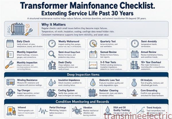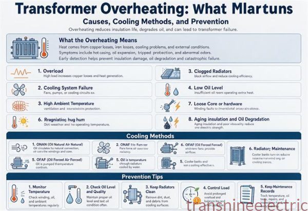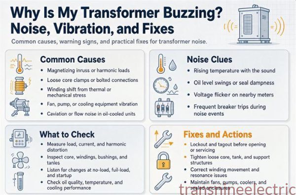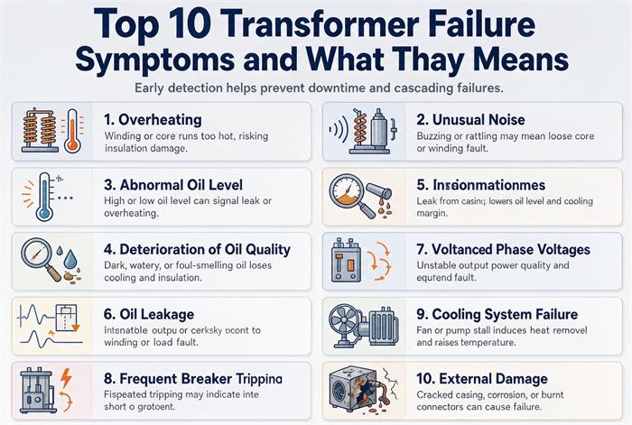
Most transformer failures announce themselves months before the lights go out. The ten symptoms below are ranked by how early they show up, not by how dramatic they look. For each one you get the physical mechanism, the number that separates watch from act, and the test that confirms it. Acetylene at 2 ppm matters more than a loud hum.
This is written for the people who actually have to make the call: plant E&I leads, facility engineers, and buyers holding a quote for a replacement unit while a 25-year-old transformer sits in the yard making a noise nobody likes. Maintenance blogs usually stop at “check your oil.” That is not a decision. What you need is the threshold, the test, and the order of operations for the next 24 hours.
Two housekeeping notes before we start. First, some of these tests only exist on liquid-filled units. A cast-resin dry-type transformer has no oil to sample and no DGA history, so symptoms 3, 4, 5, and 6 collapse into temperature, partial discharge, and insulation resistance checks. Second, the thresholds below come from published IEEE and IEC practice, and they are starting points for a conversation with your testing lab, not a substitute for one. Every number in this article is something you can hand to a technician and say “go measure that.”
If you want the full test list that a new unit should pass before it ships, our guide to routine factory tests covers the sequence from ratio to impulse. This article is the other half of that story: what the same tests tell you ten years later, when something has started to drift.
The ten symptoms at a glance
| # | What you notice | Most likely mechanism | First test | Urgency |
|---|---|---|---|---|
| 1 | Oil or winding temperature up at steady load | Cooling circuit or thermal overload | Top-oil and hot-spot trend, IR scan | Days |
| 2 | Hum changed pitch, new vibration | Core clamping, DC bias, winding movement | Sound level and vibration spectrum | Weeks |
| 3 | Oil dark, cloudy, or sludged | Oxidation, arcing byproducts | Acid number, IFT, color | Weeks |
| 4 | Acetylene on the DGA report | High-energy arcing above 700 °C | Resample in 24 h, duplicate bottle | Hours |
| 5 | Ethylene climbing faster than methane | Thermal fault above 350 °C | Duval triangle, load correlation | Days |
| 6 | Moisture over limit, furans rising | Seal breach, paper aging | Karl Fischer, 2-FAL, DP | Weeks |
| 7 | Bushing warm, chalked, or tracking | UV, pollution, moisture ingress | C1 capacitance, power factor, IR | Hours to days |
| 8 | Oil level drifting, gaskets weeping | Seal aging, bladder failure | Level vs temperature curve | Weeks |
| 9 | Tap changer hunts, stalls, or sounds off | Contact wear, carbonized LTC oil | Separate LTC oil sample, counter | Days |
| 10 | Breaker trips with no downstream fault | Insulation failure, inrush, coordination | Insulation resistance, relay targets | Hours |
If you only have five minutes, three rows in that table justify stopping everything: acetylene at any concentration above baseline, a bushing with visible tracking or a capacitance shift, and a protection operation with no fault downstream. Those three account for the failures that hurt people rather than just wallets.
How to triage a symptom in three questions
Before you spend money on a lab, ask three questions about when the symptom appears.
Does it follow load? Temperature, sound, and voltage sag that track the load curve point at the thermal and mechanical side: cooling, connections, core clamping, impedance. Drop the load by 30% and watch for ten minutes. If the symptom relaxes with it, you have a thermal problem, not a dielectric one.
Does it follow time instead? A parameter that drifts steadily across weeks at constant load is chemistry. Moisture, acid, furans, and gas generation all behave this way. These are the ones that respond to oil processing and drying, and the ones where waiting is genuinely expensive.
Did it start after a specific event? A through-fault, a lightning strike, a switching surge, a phase loss, a generator test, a nearby arc flash. Event-driven symptoms mean the unit took a mechanical or dielectric hit, and the first test is always insulation resistance plus a turns ratio check.
Answer those three and you have usually cut the list from ten to two. The rest of this article is what to do with the two.
1. Oil temperature climbs while the load stays flat
What’s actually happening inside the tank?
Heat leaves a transformer through three paths, in order of size: the oil, the radiators, and the ambient air. Anything that slows the middle step shows up as a rising top-oil temperature. Sludge on radiator fins, blocked ducts between winding discs, a fan that stopped three months ago and nobody noticed, a radiator valve left closed after the last oil top-up, or an enclosure that turned a 40 °C summer into a 55 °C intake.
The trap is blaming ambient. Ambient explains a few degrees on a hot afternoon. It does not explain 12 °C at constant load in October.
The number that decides whether you keep running
Winding hot spot, not top oil, is what ages insulation. The IEEE C57.91 loading guide uses 110 °C as the reference hot spot for 65 °C rise thermally upgraded paper, and the aging acceleration factor follows this relationship:
FAA = exp[ 15000/383 − 15000/(ΘH + 273) ]where ΘH is the hot-spot temperature in °C. Run the numbers and the curve is brutal:
| Hot spot (°C) | Aging rate | What it means in calendar time |
|---|---|---|
| 110 | 1.0× | Design life, roughly 20 to 30 years |
| 116 | 1.8× | Six degrees costs you nearly half the life |
| 120 | 2.7× | A hot summer month eats a season |
| 130 | 7.0× | One month here burns seven |
| 140 | 17× | A bad week is a bad year |
| 150 | 40× | Seven days at 150 °C costs about nine months |
Top-oil temperature typically sits 10 to 20 °C below the hot spot on a naturally cooled unit, so a gauge reading 105 °C is a hot spot near 120 °C. That is a 2.7× aging rate, and it explains why two identical transformers in the same yard have very different lives.
Two practical checks. First, compare the gauge against the winding temperature indicator, and check whether the WTI alarm and trip contacts are actually wired to anything. Plenty of units have the dial and no alarm circuit. Second, shoot the radiators with a thermal camera and compare top to bottom. A radiator that is cool at the bottom and hot at the top is not transferring heat, which usually means sludge or a closed valve rather than a failed fan.
If the fans are the problem, fix them this week. If the radiators are sludged, oil processing plus a fin cleaning buys years. If neither, you are overloaded, and the honest answer is a second unit or a larger one. Our breakdown of ONAN, ONAF, and OFAF cooling classes explains how much capacity each stage of cooling actually adds, which is the number you need before you decide to uprate rather than replace.
2. The hum changed pitch and the tank buzzes
What’s actually happening?
A healthy 60 Hz transformer hums at 120 Hz, twice line frequency, because magnetostriction in the core peaks twice per cycle. That sound is boring and constant. What you are listening for is a change in character: a sharper tone, a beat, a rattle, or a buzz that comes and goes with load.
- Louder, deeper hum at constant voltage. Core clamping pressure has relaxed, or lamination insulation has started to break down. The core is vibrating more freely than it was designed to.
- Buzz that tracks load, not voltage. Harmonic current from VFDs, rectifiers, or LED drivers. Harmonic content heats windings and excites core resonance at the same time.
- Growling plus a DC offset on the neutral. Geomagnetically induced current, a welding operation nearby, or a failing rectifier upstream. Even a small DC component pushes the core toward saturation and the sound jumps.
- Rattle or knock that comes and goes. Loose clamping structure, a loose winding block, or a tap changer mid-transition. Mechanical, and it gets worse.
How to measure instead of argue
Sound level at one meter, in dB, compared against the nameplate or the original commissioning record. ANSI/IEEE practice and NEMA TR 1 give the expected level for the rating, and distribution units commonly land in the 55 to 65 dB range. A 3 dB rise is a doubling of acoustic power, so a 6 dB jump is not “a bit louder,” it is four times the energy.
Then take a vibration spectrum. Core problems show up at 120 Hz with strong harmonics at 240 and 360 Hz. Winding looseness shows broadband energy with sidebands around 120 Hz. A spectrum turns a subjective complaint into a trend line, and a trend line is what gets a repair approved.
One field check costs nothing: tighten nothing, but look at the clamp bolts and the core ground strap. A missing or broken core ground connection causes both a buzz and stray heating, and it is a 20-minute fix if you catch it before it carbonizes the frame.
3. Oil came back dark, cloudy, or with sludge
What the color is telling you
New mineral oil is pale yellow and clear. Color is a crude indicator, but the direction of travel matters. Oil that goes from pale to amber over a decade is normal oxidation. Oil that goes dark in eighteen months is not.
The three lab numbers that decide the case:
- Acid number. Around 0.2 mg KOH/g is where most labs stop calling it normal aging and start recommending reclamation.
- Interfacial tension. Below roughly 25 mN/m means polar oxidation products have built up. New oil runs in the 40s.
- Color, ASTM D1500. Past 3.0 and you are looking at sludge precursors.
Sludge is the expensive part. It deposits on winding surfaces and blocks the cooling ducts you were relying on in symptom 1, so the two problems feed each other. A unit with dark oil and a rising top-oil temperature is not two failures, it is one failure with two gauges.
Cloudy or milky oil is different, and worse. That is free water or a paper fiber suspension, usually from a failed conservator bladder or a breather that stopped working. Free water in oil drops dielectric strength fast, and it migrates into paper at exactly the temperature where paper ages fastest.
What to do about it
Oil processing with a vacuum degasser and a fuller’s earth or activated alumina filter handles oxidation products and dissolved water in the field. It does not restore paper. Once the paper has oxidized, the furan test (symptom 6) tells you how much life is left.
If the unit is a sealed type with a nitrogen blanket, low gas pressure plus dark oil usually means the blanket is gone and the oil has been breathing moist air for a while. That combination is worth an immediate DGA plus moisture, because you are one step away from a dielectric failure that will not warn you twice.
4. Acetylene showed up on the DGA report
Why this one is different from the others
Acetylene (C₂H₂) only forms above roughly 700 °C. There is no benign reason for it to be there. Methane and ethylene can come from ordinary thermal stress. Hydrogen can come from partial discharge or even stray gassing at low levels. Acetylene comes from arcing: a loose connection drawing an arc, a tap changer diverter misbehaving, a floating potential breaking down, or a winding fault.
This is also where most online advice fails. “Monitor the trend” is the wrong instruction when acetylene appears for the first time in a unit with a clean history. Under IEEE C57.104-2019 the condition assessment combines absolute concentration against 90th-percentile values for the voltage class with the rate of change, and a first appearance of acetylene pushes a unit into Condition 3 territory on rate alone.
The 24-hour sequence
- Pull a second sample within 24 hours, from the bottom valve, in a clean syringe or bottle, and send it to the same lab that ran the first one.
- Do not operate the tap changer on load in the meantime if the unit has an OLTC. Every operation is another chance for the diverter to arc.
- Sample the OLTC compartment separately. On most designs the diverter oil is isolated from the main tank, so main-tank DGA can be clean while the diverter is carbonizing.
- Reduce load if you can, and record the reduction. The next sample needs the same load condition to be comparable.
- If the second sample confirms acetylene and the rate is rising, plan to take the unit out of service. Not “monitor monthly.” Out of service.
A rising acetylene trend with a stable load is the closest thing this industry has to a countdown timer. Units do fail from it, and they usually fail as a flashover rather than a graceful trip.
5. Ethylene is climbing faster than methane
The thermal fault signature
Methane appears above about 150 °C, ethylene above about 350 °C. So the ratio between them is a thermometer for the inside of the tank. Methane high with ethylene low means mild thermal stress, often just heavy loading. Ethylene climbing while methane plateaus means the hot spot has moved past 350 °C and is heading for the range where paper starts to carbonize.
The classic interpretation path is the Duval triangle, which plots methane, ethylene, and acetylene percentages to separate thermal faults, low-energy discharge, and high-energy arcing. Rogers ratios do the same job with different axes. Either way, a lab report that gives you gas concentrations without a diagnosis is half a report.
The two things people get wrong
Comparing to limits instead of to yourself. A 300 kVA unit and a 20 MVA unit have different normal ranges, and a GSU on a wind farm has a different history than a plant transformer. The most useful comparison is the same unit, same season, same load band, twelve months apart.
Ignoring the CO and CO₂ pair. Ethylene tells you the oil got hot. CO and CO₂ tell you the paper got hot, and paper does not recover. A CO₂/CO ratio that falls below roughly 3 points at cellulose involvement in the fault rather than ordinary oil oxidation, while a ratio above 10 is the normal aging range. Rising CO₂ with a falling ratio is the pattern that means insulation is being consumed, not just stressed.
If the thermal fault is real, the fix is usually mechanical: a high-resistance connection at a bushing terminal, a bad weld in a winding, or blocked cooling in one section. None of those are fixable without opening the unit, which means the decision is repair versus replace, and that decision has a lead-time problem attached to it.
6. Moisture is over the limit, or furans are rising
Two tests, two different questions
Water in oil is a present-tense question: can this insulation hold voltage right now? Water in paper is a future-tense question: how much life is left? Most maintenance programs run the first test and skip the second.
For the present tense, Karl Fischer titration gives water content in ppm, and IEEE C57.106 sets limits that tighten with voltage class, roughly 20 ppm at distribution voltages down to about 10 ppm at transmission levels. Confirm the edition your lab reports against, because the tables have been revised.
For the future tense, two tests matter. Furfural (2-FAL) is a paper degradation product that stays in the oil, and it correlates with degree of polymerization. Above roughly 1 ppm you are into measurable paper aging, and by the time it reaches several ppm the paper is brittle enough that a through-fault will crack it. Degree of polymerization itself requires a paper sample, which usually means waiting until the unit is open for another reason.
Why moisture is a compounding problem
Water does two things at once. It cuts the dielectric strength of both oil and paper, and it accelerates hydrolysis of the cellulose chain. The commonly used rule is that each doubling of water content in paper roughly doubles the aging rate. Going from 0.5% to 2% is two doublings, which is about four times the aging rate, on top of whatever temperature is doing.
The temperature dependence is the part people miss. Paper at 60 °C holds far more water than paper at 20 °C, so a unit that tests fine in winter can be saturated in July. Always evaluate moisture against the oil temperature at the time of sampling, and ask the lab for relative saturation, not just ppm.
Where the water comes from
Ranked by how often it is the real cause: a failed conservator bladder letting humid air sit on the oil, a silica gel breather that went pink months ago, gasket shrinkage on a unit that cycles hot and cold daily, and condensation in a sealed tank with a nitrogen blanket that leaked out. Fixing the source is cheaper than drying the oil, and drying without fixing the source means you will do it again next year.
7. A bushing is warm, chalked, or showing track marks
The failure that skips the warning
Bushings deserve their own section because they fail differently from everything else in this article. A bushing can go from “slightly warm” to “phase-to-ground flashover” in a single weather event, and the failure mode is often external tracking along a polluted, wetted surface rather than anything happening inside the tank.
What to look for on inspection:
- Chalking or a dull, faded sheds. UV degradation of the housing material. The surface is now hydrophilic, which is exactly what you do not want in rain.
- Brown or black tracking lines from the flange upward. Surface discharge has already started. This is a replace-now finding, not a clean-and-monitor finding.
- A warm bushing relative to its neighbors. Thermal camera, same load, same ambient. A 10 °C delta between phases is worth a capacitance test.
- Oil weep at the flange or a cracked porcelain. Moisture ingress into a condenser-graded bushing is a slow death with a fast ending.
Field practice commonly flags a bushing when C1 capacitance has shifted about 5% from the nameplate value, or when power factor has climbed noticeably above the commissioning value. A dropping capacitance with rising power factor means moisture or partial discharge inside the condenser core, and that bushing is on a clock.
What to do if it is already tracking
A bushing with visible tracking does not get cleaned and returned to service. It gets replaced, because the tracking path is carbonized and the surface will not recover its hydrophobicity. This is also the place where a $400 part takes out a $40,000 transformer. If you are replacing bushings on a unit that is staying in service, specify the same creepage class or better, and check that the connector hardware matches the conductor material. Aluminum-to-copper joints in a wet environment are a corrosion cell that heats up over years.
8. Oil level drifts and gaskets weep
Small leaks, large consequences
A weep at a gasket is not urgent. A weep plus a falling level plus a unit that runs hot is a different story, because the oil you are losing is also the coolant and the insulator.
The diagnostic trick is to plot oil level against oil temperature for a week. On a healthy unit with a conservator, level tracks temperature in a predictable band. If the level is lower than the band at every temperature, you have lost oil. If the level drops while temperature is stable, you have an active leak. If the level rises without a temperature rise, you have water entering, and that is the worst of the three.
For sealed units with a nitrogen blanket, pressure is the tell. A blanket that needs recharging monthly has a leak, and the leak is letting moisture in as fast as it lets nitrogen out.
The compliance angle nobody mentions
In the US, a transformer with more than 1,320 gallons of oil in a single above-ground container, or more than 660 gallons in a single container, can fall under SPCC planning requirements for oil storage. A 1,000 kVA distribution unit commonly holds 200 to 300 gallons, and a 1,500 kVA unit can approach 500. Add a second unit on the same pad and you can cross the threshold without anyone noticing. A chronic leak on a site that has crossed it turns a maintenance item into a regulatory one.
Outdoor pads need a containment plan either way. A 300-gallon spill that reaches a storm drain costs more than every repair in this article combined.
9. The tap changer hunts, stalls, or sounds different
The component that fails most
On-load tap changers show up at or near the top of every transformer reliability survey, and the reason is mechanical: they are the only part of a transformer that moves under load, and they move thousands of times a year.
Symptoms worth acting on:
- Voltage regulation oscillating. The automatic control is hunting between taps. Usually a control setting, a CT ratio, or a worn motor mechanism, and occasionally a sign that the diverter contacts are not making cleanly.
- A longer pause between tap positions, or a louder clunk. Motor or spring mechanism losing energy. On a vacuum-type OLTC this is often the first audible sign.
- A burnt smell near the OLTC head, or a carbonized oil sample. Arcing in the diverter. This is the one that ends in a tank rupture if ignored.
- Tap position indicator disagreeing with actual output voltage. Lost calibration or a slipping coupling, which means the unit is running at a tap nobody intended.
Sample the right compartment
This is the single most common diagnostic error in the field. On most OLTC designs the diverter switch sits in its own oil compartment, isolated from the main tank. A clean main-tank DGA says nothing about the diverter. Sample both, label both, and never mix the results in one report.
A diverter sample that comes back with acetylene and a carbonized appearance means the contacts are arcing in the wrong place, and the fix is a contact inspection, not an oil change. Contact wear limits are in the OLTC manufacturer’s manual, and they are usually expressed in number of operations, not years. If nobody has been logging the operation counter, you do not know where you are.
A de-energized tap changer is a different animal. It moves maybe a dozen times in its life, so mechanical wear is not the issue. The issue is contact pressure and whether the last person to change taps torqued the connections. If a unit was re-tapped during commissioning and the voltage has been slightly off ever since, start there before you suspect the windings.
10. Breakers trip with no downstream fault
Separate the two causes first
A protection operation with no fault on the feeder means one of two things: the transformer has an internal problem the relay caught, or the relay caught something that was not a problem. Those have opposite remedies and you cannot tell them apart from the breaker alone.
Read the relay targets before anyone resets anything. A differential trip with second-harmonic restraint satisfied means the relay saw current going in that did not come out. A sudden-pressure or Buchholz trip means gas moved fast inside the tank. An overcurrent trip with no downstream fault is the ambiguous one, and it is usually one of these:
- Magnetizing inrush. Energizing a unit draws 8 to 12 times full-load current for a fraction of a second, decaying over a second or so. If the primary protection is a fuse or a breaker with instantaneous settings, inrush can trip it, especially on a unit that was switched in at a voltage zero crossing.
- Coordination failure. The transformer primary device is set below the downstream feeder device, so the wrong breaker opens first.
- A real internal fault. Insulation resistance and a turns ratio test will find it, and a DGA sample will confirm it.
The NEC numbers that keep coming up
For units under 1,000 V, NEC 450.3(B) permits primary-only protection at 125% of primary full-load current, with the next standard rating up allowed where 125% does not land on a standard size. Standard ratings come from NEC 240.6(A): 800, 1000, 1200, 1600, 2000, 2500, 3000, 4000 A and up. Note there is no 1,400 A and no 1,800 A in that list, which is where a lot of hand calculations go wrong.
For continuous loads, NEC 215.2 requires conductor ampacity of at least 125% of the continuous load plus 100% of the noncontinuous load. And NEC 240.4(C) is the trap: above 800 A, the overcurrent device cannot exceed the conductor ampacity. There is no next-size-up allowance up there, so a conductor sized at 900 A cannot be protected by a 1,000 A breaker on the basis of “close enough.”
If the trips started after a load addition, the arithmetic is usually the answer. If they started after a thunderstorm, the answer is usually insulation. Test for both before you re-energize, because a transformer that trips twice for the same unexplained reason is telling you something.
Three symptoms that hide inside the ten
Some findings do not get their own row in the table because they look like something else.
Neutral current that will not go away. A four-wire system with a persistent neutral current and balanced phase voltages points at triplen harmonics or a winding problem, not at the load. Clamp the neutral and compare it to phase current. On a healthy balanced system it should be small. If it is 30% of phase current with no single-phase load to explain it, look at the zero-sequence path.
A hot-varnish smell in a dry-type room that “always smelled like that.” Cast resin does not normally smell. A faint phenolic or varnish odor that gets stronger in the afternoon is overheating insulation, and by the time it is obvious you have already spent aging life. Thermal scan the winding faces and compare the three phases.
A relay target that was reset “because it was probably a surge.” Every unexplained operation is data. Log the date, the load, the weather, and the target, and keep the log where the next person can find it. Three unexplained operations in a year is a pattern, and the pattern is the diagnosis.
What waiting actually costs
The reason to rank symptoms by lead time rather than drama is that the economics are wildly asymmetric. A fan motor is a few hundred dollars. A rewind is tens of thousands. A new unit is tens of thousands plus a lead time you cannot compress.
| Finding | Typical corrective action | Realistic lead time |
|---|---|---|
| Cooling fan or pump failure | Replace motor or pump | Days, often off the shelf |
| Moisture over limit, seals intact | Vacuum dehydration, oil processing | 1 to 2 weeks |
| Sludged oil, paper still healthy | Oil reclamation plus fin cleaning | 2 to 4 weeks |
| OLTC contact wear | Contact replacement, gasket kit | 3 to 8 weeks |
| Bushing replacement | Standard bushing, same creepage class | 1 to 3 weeks |
| Winding fault on a standard rating | Rewind or replacement | 8 to 16 weeks |
| Winding fault on a non-standard rating | New unit, custom build | 16 to 20 weeks or more |
| Large power transformer failure | New unit, factory slot | 12 to 24 months |
The gap between the first four rows and the last four is the entire argument for condition monitoring. Catching a $600 fan failure prevents a $60,000 rewind, and the only skill required is looking at the temperature gauge with the load in mind.
There is a second asymmetry. A repair scheduled during a planned outage costs the repair. A repair forced during production costs the repair plus the lost output plus the expedite premium, which in most markets runs 25% to 35% above a normal order. Buyers who call a manufacturer after the failure pay for both.
What to specify so the same symptom does not come back
If you are replacing the unit, the failure is a specification problem as much as an age problem. Five items in the RFQ change the odds.
Temperature rise and cooling class. A unit specified at 65 °C rise runs hotter than one at 55 °C rise, and runs a shorter life at the same load. If the old unit lived its whole life near its thermal limit, specify the next cooling stage up or a lower temperature rise, and accept the extra cost. It is cheaper than the replacement cycle you just lived through.
Impedance, stated as a guaranteed value with tolerance. Percent impedance sets both the fault current the downstream gear sees and the voltage dip your process sees during a motor start. ANSI/IEEE C57.12.00 allows a tolerance of roughly ±7.5% on the declared value, so ask for the calculated value and the test value. A unit that comes in 7% low on impedance passes the standard and delivers 7% more fault current than your coordination study assumed.
Harmonic duty, stated honestly. If the load is VFDs, rectifiers, or IT equipment, say so and ask for a K-factor rating (K-4, K-13, K-20 under UL 1561 for units up to 600 V) or a derated standard unit. A standard transformer on a K-13 load runs hotter than its nameplate suggests, which is symptom 1 with a predictable cause.
Monitoring provisions, wired and terminated. Winding temperature indicator with alarm and trip contacts actually connected. Top-oil indicator. A DGA sampling valve that a technician can reach without a ladder and a permit. A pressure relief device with a contact. These add very little to the price at the factory and a great deal to the resale value of your maintenance program.
Efficiency, with the 2029 floor in mind. The US DOE amended distribution transformer efficiency standard takes effect on April 23, 2029, and the compliance table in 10 CFR 431.196 tightens no-load loss again. A unit built to the current table will run warmer and lose more than one built to the 2029 table. If the replacement is going to be in service for thirty years, ask the manufacturer which table the design is built against and get it in writing. The regulatory text sits in 10 CFR Part 431, Subpart K, and the DOE appliance standards program publishes the compliance dates.
On the standards side, the difference between an IEC-designed and an IEEE-designed unit shows up in exactly the places these symptoms live: temperature rise basis, impedance tolerance, sound level limits, and test sequence. Our comparison of IEC 60076 and ANSI/IEEE requirements covers which clauses to cite in a specification. The nameplate guide covers what to check on delivery, and the full buying guide walks the rest of the procurement sequence.
Nothing above is exotic. Cast-resin dry-type units skip the oil-related symptoms entirely and trade them for stricter temperature and partial discharge monitoring. Either way, the specification work is the same: state the duty, state the environment, and get the guaranteed values in writing.
FAQ
How often should a transformer’s oil be tested for dissolved gas?
Annually for units in normal service, quarterly for units above roughly 10 MVA or any unit with a prior fault history, and within 24 hours of a through-fault or a protection operation. After any abnormal result, the follow-up interval drops to days, not months, because gas generation rates are more diagnostic than absolute concentrations.
Can a transformer fail without any warning symptoms at all?
Rarely, and almost never without a measurable precursor. Bushing flashover is the closest thing to a sudden failure, and even that usually has visible tracking, chalking, or a capacitance shift beforehand. The failures that look sudden are usually the ones where nobody was sampling, scanning, or logging.
What acetylene level means I should take the unit offline?
Any acetylene above the detection limit in a unit with no prior acetylene history is a stop-and-investigate finding, and a confirmed rising trend on a second sample within 24 hours is grounds for outage. IEEE C57.104-2019 assesses condition on concentration against 90th-percentile values plus rate of change, and a first appearance scores badly on rate regardless of the ppm number.
How much does a hot spot really shorten transformer life?
Following the IEEE C57.91 relationship, a hot spot of 120 °C ages insulation about 2.7 times faster than the 110 °C reference, 130 °C ages it about 7 times faster, and 150 °C ages it about 40 times faster. In calendar terms, one week at 150 °C consumes roughly nine months of design life.
Is a loud hum always a sign of failure?
No. Hum at 120 Hz is normal on a 60 Hz system. What matters is a change from the unit’s own baseline, a tone that shifts with load, or a new rattle. A 3 dB rise doubles acoustic power, so a 6 dB increase is four times the sound energy and worth a vibration spectrum.
Do dry-type transformers have the same failure symptoms?
Only partly. There is no oil to sample, so DGA, moisture-in-oil, and acid number do not apply. The equivalents are winding temperature, partial discharge testing, insulation resistance, and visual inspection for tracking and dust buildup on winding surfaces. Cast-resin units fail more often from overheating and surface contamination than from internal arcing.
How long does a replacement transformer take if mine fails?
Eight to sixteen weeks for a standard rating from a stocked or semi-stocked line, sixteen to twenty weeks or more for a non-standard rating, and twelve to twenty-four months for a large power transformer. Emergency orders carry a premium commonly quoted at 25% to 35% above normal pricing, which is why the monitoring calendar is cheaper than the spare.
Should I repair or replace a transformer with a winding fault?
Repair when the core and tank are sound, the rating is standard, and the unit is under about 20 years old. Replace when the fault is on a non-standard rating, when oil processing cannot get acidity under control, or when the unit has already been rewound once. A second rewind on the same core rarely pays back, because the paper and the clamping structure have both taken the hit.