a three phase transformer is three windings on one core, and it’s the default choice for anything above roughly 15 kVA of motor or panel load. Buying one comes down to five numbers — kVA, voltage ratio, vector group, impedance, and temperature rise — plus two things most guides skip: whether federal efficiency rules reach it, and whether the breaker you picked will survive energizing it.
Everything else you’ll read about this topic falls into two piles. One pile explains what three-phase power is and lists applications. The other runs the NEC arithmetic for a 480 V to 208Y/120 V step-down. Both are fine, and neither mentions that the more efficient the transformer you buy, the more likely you are to trip the primary breaker on day one. That connection is real, it’s documented, and it’s not in any of the eleven pages currently ranking for this keyword.
TransNine Electric builds dry-type, cast resin, and liquid-immersed units for export, and what follows is the order we’d want you to make decisions in.
Key numbers
| Item | Value | Why it matters |
| Standard 3-phase kVA steps | 15, 30, 45, 75, 112.5, 150, 225, 300, 500, 750, 1,000 | You round up to one of these; you don’t order 68 kVA |
| 75 kVA, 480 V → 208Y/120 V | 90.2 A primary / 208.2 A secondary | The two numbers every downstream device is sized from |
| NEC 450.3(B), primary only, ≥9 A | 125% ceiling | Lowest-cost path, and the one that nuisance-trips |
| NEC 450.3(B), primary + secondary | 250% primary / 125% secondary | Adding secondary protection buys inrush headroom |
| NEC 450.3(B), small primaries | 167% (2–8.99 A), 300% (<2 A) | Small control transformers would trip on 125% |
| NEMA ST 20 short-circuit withstand | 20–25× FLA for 2 seconds | What the transformer itself can take |
| Magnetizing inrush | Historically 4–10× FLA; up to 20–30× on high-efficiency designs | Why a 125% device can trip on a healthy transformer |
| DOE coverage — input / output | ≤34.5 kV / ≤600 V | 10 CFR 431.192 |
| DOE coverage — frequency | 60 Hz | A 50 Hz unit isn’t covered (and isn’t right for a US feeder) |
| DOE coverage — capacity | 10–5,000 kVA liquid, 15–5,000 kVA dry-type | Nearly every distribution-class unit lands inside |
| DOE compliance trigger | Manufactured or imported on or after April 23, 2029 | 89 FR 29834; PO date is irrelevant |
| 1 kW of core loss | 8,760 kWh per year ≈ $1,218 at 13.9 ¢/kWh | Core loss runs 24/7 regardless of load |
| Core vs winding crossover | Roughly 0.32–0.45 load factor | Below it, core dominates; above it, winding does |
| Ratings basis | ≤1,000 m (3,300 ft); 40 °C max / 30 °C daily avg / 20 °C annual avg | Above or beyond these, you derate |
| Open-delta (two units) | 57.7% of closed-delta capacity | The cost of running a bank on two legs |
What three-phase actually buys you
Three-phase power delivers constant instantaneous power instead of the pulsing you get from single phase, which is why motors run smoother, run cooler, and don’t need a start winding or a capacitor. For the same delivered power, three-phase also moves it over less copper. Above roughly 15 kVA, there’s no real argument.
Below that, there usually is. A small shop with lighting, a few receptacles, and one 3 hp machine doesn’t need three-phase service. And there’s a middle case worth knowing about: you can build three-phase capacity out of three single-phase units. Utilities do this constantly, because a bank of three lets you stock one spare instead of one of each size, and because losing one unit doesn’t have to mean losing the service. Two of the three can keep you alive in what’s called open-delta — but that configuration delivers only 57.7% of the closed-delta capacity, so you’re trading a lot of headroom for that spare strategy.
For a building or a plant, one three-phase unit is almost always the answer: smaller footprint, less core steel, lower losses, and one set of terminations instead of three.
The five specs that decide everything
Everything on a three-phase transformer spec sheet rolls up into five numbers. Get these right and the rest is paperwork.
1. Capacity, in kVA — not kW. Windings carry apparent power regardless of power factor, which is why the nameplate is in kVA. If your load schedule is in kW, divide by power factor: 150 kW of motors at 0.85 PF is 176.5 kVA, not 150 kVA. Skipping that division is the single most common sizing error.
2. Voltage ratio and taps. Name both sides, and say whether you want a wye secondary with a brought-out neutral. Taps compensate for supply variation: ±2 × 2.5% is the usual offering, wider on request. Taps are set at manufacture — a unit built as 13.8 kV / 480 V cannot be re-rated later.
3. Vector group. This is the one nobody specifies and everybody should. The common notation — Dyn11, Yyn0, Dd0, YNd11 — tells you three things at once: winding connections on each side, whether a neutral exists, and the phase displacement between primary and secondary. Dyn11 (delta primary, wye secondary with neutral, 30° displacement) is the distribution workhorse: it gives you 208Y/120 V from a 480 V delta feed, and it traps triplen harmonics in the delta so they don’t propagate back into the source. Yyn0 also gives you a neutral, but its neutral-current capability is limited — check the nameplate value before you hang single-phase loads on it, and never parallel Yyn0 with Dyn11. Dd0 has no neutral at all.
If you ever plan to run two units in parallel, the vector group has to be identical, the impedances need to be close (within roughly 10% is the usual rule of thumb), and both units need to sit on the same tap position. Get any of those wrong and you get circulating current at no load.
4. Impedance, in percent. Impedance is the dial that trades fault current against voltage drop. Low impedance means better regulation and higher available fault current; high impedance protects downstream gear by choking fault current but costs you voltage under load. Typical distribution values run 4% to 6% for smaller units and 5.75% is a common 1,000 kVA figure. Whatever you pick sets the interrupting rating of everything downstream, so calculate it — don’t inherit it.
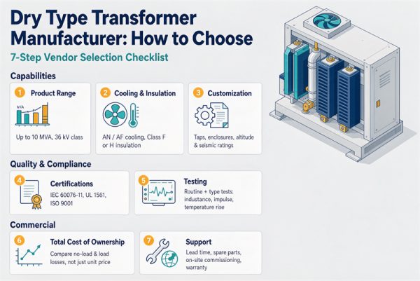
5. Temperature rise and insulation class. Dry-type nameplates commonly read 80 °C, 115 °C, or 150 °C average winding rise over a 40 °C ambient. A higher-rise unit is smaller and cheaper for the same kVA and runs hotter, which is a real trade against insulation life. Liquid-immersed units are rated differently, by top-oil and winding rise per IEC 60076 or IEEE C57.12.00, and their cooling designation (ONAN, ONAF) tells you whether you have fans.
If any of these five looks unfamiliar on a quote, the transformer nameplate guide walks through reading one line by line. The full range we build is on the products page.
Sizing: from load schedule to a standard kVA
Four steps, and the third one is where most quotes go wrong.
Step 1 — Convert to kVA. kVA = kW ÷ power factor. If you’re working from amperes instead: kVA = (V × A × √3) ÷ 1,000 for three-phase.
Step 2 — Apply the continuous-load factor. NEC treats loads running three hours or more as continuous and requires them counted at 125%. A panel with 120 A of lighting and HVAC plus 40 A of receptacles is a calculated load of 120 × 1.25 + 40 = 190 A, not 160 A.
Step 3 — Add margin deliberately. Not a reflex 20%. Margin covers motor starting, load growth, and harmonics, and those are three different numbers. A stable lighting and HVAC panel might justify 10%. A panel feeding VFDs or a bank of servers justifies more — see the harmonics section below.
Step 4 — Round up to a standard size. Here’s the worked version: 176.5 kVA of motor load, 10% margin → 194.1 kVA → next standard size 225 kVA.
Then convert the size into amps, because everything downstream is sized from current, not kVA. For 480 V delta primary to 208Y/120 V wye secondary:
| kVA | Primary FLA @ 480 V | Secondary FLA @ 208 V |
| 15 | 18.0 A | 41.6 A |
| 30 | 36.1 A | 83.3 A |
| 45 | 54.1 A | 124.9 A |
| 75 | 90.2 A | 208.2 A |
| 112.5 | 135.3 A | 312.3 A |
| 150 | 180.4 A | 416.4 A |
| 225 | 270.6 A | 624.5 A |
| 300 | 360.8 A | 832.7 A |
| 500 | 601.4 A | 1,387.9 A |
| 750 | 902.1 A | 2,081.8 A |
| 1,000 | 1,202.8 A | 2,775.7 A |
One caution about published charts. Several list a “maximum secondary breaker” that doesn’t match 125% of the FLA they printed — a 75 kVA row showing 225 A when 208.2 × 1.25 = 260 A. That’s not necessarily a code violation, because Table 450.3(B) sets a ceiling and not a target. But it’s exactly the kind of number that produces a call-back on energization day, which brings us to protection.
Protecting it: the NEC 450.3(B) arithmetic, and the trap inside it
Table 450.3(B) governs overcurrent protection for transformers rated 1,000 V and less. The percentages are maximums:
| Protection arrangement | Primary ceiling | Secondary ceiling |
| Primary only, ≥9 A | 125% | Not required |
| Primary only, 2–8.99 A | 167% | Not required |
| Primary only, <2 A | 300% | Not required |
| Primary + secondary | 250% (any primary current) | 125% (≥9 A) / 167% (<9 A) |
Two notes matter as much as the table. Where 125% doesn’t land on a standard device rating, you may go to the next higher standard rating (NEC 240.6 ladder). And where the manufacturer provides coordinated thermal overload protection, the primary device may go as high as 6× rated current for units of 6% impedance or less, or 4× for units above 6% up to 10%.
Worked example, 112.5 kVA, 480 V → 208Y/120 V, protected on both sides:
- Primary FLA 135.3 A → 250% = 338.2 A → next standard size 350 A
- Secondary FLA 312.3 A → 125% = 390.4 A → next standard size 400 A
Same unit, primary protection only: 135.3 A → 125% = 169.1 A → next standard 175 A. That’s a much tighter device, and here’s where it bites you.
Why high-efficiency cores trip breakers
When you energize a transformer, the core has to magnetize, and for the first few cycles it draws far more than rated current. Historically that inrush was typically 4 to 10 times primary FLA, and a 125% device rode through it fine. Eaton’s dry-type installation white paper is blunt about what changed: after the 2007 and 2016 DOE efficiency tiers pushed core designs harder, theoretical maximum inrush can reach 20 to 30 times FLA, and nuisance tripping of primary devices sized at 125% became a documented field problem.
The mechanism is simple. Higher-efficiency cores run closer to saturation, and a saturated core draws more magnetizing current. So the rule you were taught — size the primary at 125% and move on — is now the setting most likely to fail on a brand-new, code-compliant, high-efficiency transformer.
What to do about it:
- Protect both sides. It’s the cheapest fix. Secondary protection at 125% lets the primary go to 250%, and that headroom is what absorbs inrush.
- Ask for the actual inrush value. Manufacturers can give you a measured or predicted multiple for the specific design. Don’t accept “typical range” on a unit you’re putting on a tight feeder.
- Check that the device can ride through. Time-delay fuses and high-magnetic (HACR) breakers behave differently from a standard thermal-magnetic unit on a 3-cycle spike.
- Remember the percentages are ceilings. Nothing requires you to sit at 125%.
Also worth noting: per NEMA ST 20, a dry-type transformer is required to withstand 20–25× FLA for 2 seconds. The transformer will almost certainly survive the event that trips your breaker. The breaker is the weak link, not the transformer.
Efficiency: the coverage test, the date, and the dollars
Federal efficiency rules apply to the transformer, and whether yours is covered is a four-question test under 10 CFR 431.192. A “distribution transformer” has:
- Input line voltage ≤34.5 kV
- Output line voltage ≤600 V
- Rated for 60 Hz
- Capacity 10–5,000 kVA liquid-immersed or 15–5,000 kVA dry-type
A 480 V to 208Y/120 V dry-type unit at 60 Hz clears all four. A 13.8 kV to 480 V liquid unit clears all four. A step-up unit with a 34.5 kV secondary does not — its output is above 600 V. The definition also carries thirteen exclusions, including autotransformers, drive (isolation) transformers, rectifier and special-impedance transformers, and anything with a tap range of 20% or more.
The date that matters is the manufacturing or import date. Per DOE’s April 2024 final rule (89 FR 29834), amended levels apply to units manufactured or imported on or after April 23, 2029. A unit built in late 2028 and delivered in 2029 is judged on the current table. And pull the actual number for your rating out of 10 CFR 431.196 rather than accepting “meets DOE” — in the liquid-immersed three-phase table the curve isn’t monotonic, and a 300 kVA unit is held to a stricter value than a 500 kVA unit.
Then turn watts into money, because that’s the comparison that actually ranks two quotes.
Core loss runs 8,760 hours a year whether you load the unit or not. One kilowatt is 8,760 kWh annually — about 1,218 per kW per year** at an illustrative 13.9 ¢/kWh. If quote A's certified no-load loss is 400 W above quote B's, that's 3,504 kWh a year, roughly **487, and about $12,000 over 25 years with no escalation. Plug in your own tariff.
Winding loss behaves differently: it scales with the square of load. At 60% load factor you only realize 36% of rated load loss. That difference is what tells you which upgrade to pay for:
- Rated load loss is commonly several times core loss for distribution-class units — call it 5 to 10×
- Setting winding loss equal to core loss, the crossover sits at a load factor of about 0.32 to 0.45
- Below that, buy the better core. Above it, buy lower winding loss — heavier conductor, usually copper
Dry-type or liquid-immersed, and where it can live
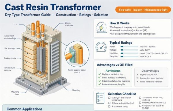
Dry-type is the indoor default: no oil, no containment, no fire pump. Within dry-type there are two flavors worth distinguishing — ventilated (VPI/VPE, the workhorse for clean indoor rooms) and cast resin (windings encapsulated in epoxy, which handles humidity, dust, salt air, and coastal exposure). UL 1561 is the standard dry-type units are listed to.
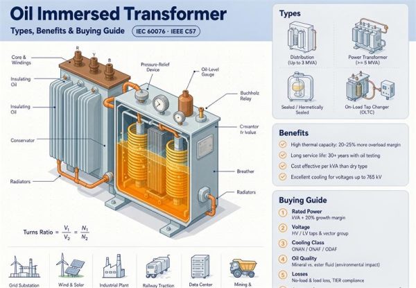
Liquid-immersed wins outdoors and at higher capacities: better heat transfer, better overload capability, longer life in harsh environments, and lower cost per kVA at the top end. The trade is a fluid to manage. Mineral oil is cheapest; natural and synthetic esters have fire points above 300 °C, which is the threshold in NEC 450.23 that changes what you’re allowed to do near combustible construction. UL 1562 is the listing standard for liquid-immersed units.
Whether you can put a given unit indoors is mostly a ventilation and fire-separation question, not a transformer question. NEC Article 450 covers transformer rooms, and 110.26 sets working space — roughly 3 ft to 4 ft of clearance depending on voltage and condition. Check both before you draw the room.
The full trade-off is laid out in our oil-immersed vs dry-type comparison, and the dry-type range covers ventilated and cast resin construction up to 2,500 kVA. If you’re specifying a liquid unit, the cooling designation on the nameplate isn’t decoration — ONAN versus ONAF changes both the rating and whether you have fans to maintain, and our cooling classes guide breaks down the letter code.
The site conditions that quietly derate a unit
Four things shrink a transformer after you’ve already paid for it, and all four belong on the RFQ rather than in a phone call.
Altitude. Ratings assume installation at or below 1,000 m (3,300 ft). Above that, air is thinner, cooling degrades, and external clearances lose dielectric margin. There isn’t one universal derating constant — manufacturers publish curves, so ask for the curve in writing and name your site elevation. Denver, Salt Lake, and most of the Mountain West are above the line.
Ambient temperature. Standard ratings are built on 40 °C maximum, 30 °C daily average, and 20 °C annual average. A poorly ventilated electrical room hitting 50 °C in July isn’t a 40 °C environment, and the unit has to be derated or force-cooled.
Harmonics. Switch-mode power supplies, VFDs, LED drivers, UPS systems, and DC fast chargers all generate triplen harmonics that circulate and heat windings in ways FLA math doesn’t capture. Two options: specify a K-factor rated transformer (K-13 or K-20, with the K number derived from the measured harmonic spectrum), or oversize a standard unit and accept the heating. Oversizing is the lazy answer and it doesn’t fix neutral heating. For a look at what a K-rated program looks like in practice, see our K-factor transformer project for a hyperscale data centre.
Duty cycle. Steady load, cyclic load, and standby duty age insulation differently. A unit that sits at 25% for nine months and 95% for three is not the same purchase as one that runs flat at 60% — and it changes which loss tier pays back.
The RFQ block
Copy this into your inquiry. Every line is a blank that costs money to fill in wrong.
More background on what each routine test actually proves is in the resources library.
Frequently asked questions
What is a three phase transformer?
A transformer with three sets of primary and secondary windings on a common core, used to change voltage in a three-phase AC system. Compared with three separate single-phase units, one three-phase transformer is generally smaller, lighter, and cheaper for the same rating. Above roughly 15 kVA it’s the standard choice for motor loads and commercial panels.
How do I size a three phase transformer?
Convert your load to kVA (kW ÷ power factor, or V × A × √3 ÷ 1,000), apply the 125% factor to any continuous load, add margin for motor starting and growth, then round up to a standard size. A 150 kW motor load at 0.85 PF is 176.5 kVA; with 10% margin that’s 194.1 kVA, which rounds up to 225 kVA.
Why is 480 V to 208Y/120 V so common in US commercial buildings?
Because one secondary serves both: 208 V line-to-line for three-phase equipment and HVAC, and 120 V line-to-neutral for lighting and receptacles. It’s the default step-down behind a commercial panel, and it’s why most dry-type three-phase catalogs are organized around that ratio.
What does Dyn11 mean and why does it matter?
The letters give winding connections — capital for the high-voltage side, lowercase for the low-voltage side — and the number is the clock position of the phase displacement. Dyn11 is a delta primary, a wye secondary with a brought-out neutral, and 30° displacement. It’s the distribution default because it gives you a neutral and it traps triplen harmonics in the delta instead of sending them back into the source. It also matters for paralleling: you cannot parallel units with different vector groups.
Can I parallel two three phase transformers?
Yes, if four things match: vector group, voltage ratio, impedance (within roughly 10%), and tap position. Mismatched vector groups produce a voltage difference across the tie and drive large circulating currents with no load connected. Mismatched impedance means the units won’t share load in proportion to their ratings.
What size breaker do I need for a 75 kVA three-phase transformer?
Start from full-load current: 75,000 ÷ (480 × √3) = 90.2 A primary, and 75,000 ÷ (208 × √3) = 208.2 A secondary. Primary-only protection caps at 125% → 112.8 A → next standard size 125 A. Protect both sides and the primary ceiling rises to 250% → 225.5 A → 250 A, with the secondary at 125% → 260 A → 300 A. Note that 125% is a ceiling, not a target, and that high-efficiency designs may need the extra headroom to ride through inrush.
Do DOE efficiency rules apply to three phase transformers?
Often yes. Under 10 CFR 431.192, coverage requires an input of 34.5 kV or less, an output of 600 V or less, 60 Hz operation, and a capacity of 10–5,000 kVA liquid-immersed or 15–5,000 kVA dry-type. A 480 V to 208Y/120 V unit meets all four. A step-up unit with a medium-voltage secondary does not. Amended levels apply based on manufacturing or import date, not purchase order date.
Dry-type or oil-filled — which should I buy?
Dry-type for indoor, fire-sensitive, or low-maintenance sites; no oil means no containment and no oil testing. Liquid-immersed for outdoor, higher-capacity, or harsh-environment duty, where the cooling and overload capability are worth the fluid maintenance. Indoor liquid installations near combustible construction bring NEC 450.23 into play, and an ester fluid with a fire point above 300 °C can simplify that conversation.
Why does my transformer trip the breaker when I energize it?
Almost always magnetizing inrush. The core draws several times rated current for the first few cycles, and on modern high-efficiency designs that multiple can be far higher than the 4–10× figure older practice assumed. Fixes, in order: add secondary protection so the primary ceiling rises to 250%, use a time-delay or high-magnetic device, or get the manufacturer’s actual inrush value and coordinate to it. The transformer itself is usually fine — NEMA ST 20 requires dry-type units to withstand 20–25× FLA for 2 seconds.
Do I need a K-rated transformer?
If a large share of your load is non-linear — VFDs, switch-mode supplies, LED drivers, UPS systems, DC fast chargers — yes, or you need to oversize and accept the heating. K-13 and K-20 are the common ratings, and the right one comes from the measured harmonic spectrum, not from a guess. Oversizing a standard unit doesn’t address neutral heating from triplen harmonics.