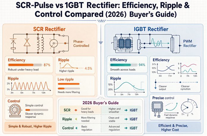
An SCR rectifier switches at line frequency (50/60 Hz) and controls output by delaying its firing angle — cheap and tough, but 5–15% ripple and modest control. An IGBT rectifier switches at 15–30 kHz with full on/off PWM, cutting ripple under 3%, lifting power factor near 0.99, and enabling precise CV/CC/pulse control at a higher upfront price.
Key takeaways (read this if nothing else):
- SCR = a line-frequency dimmer. Cheap, rugged, 20–40 year life, but 5–15% ripple and slow, coarse control.
- IGBT = a high-speed digital dimmer. 90–96% efficient, <3% ripple, near-unity PF, full CV/CC/CP + pulse control — for ~1.5–2.5x the price.
- Neither is obsolete. Pick by duty cycle, chemistry, grid tariff, and who services it, not by hype.
- IGBT usually pays back its premium in 12–36 months on energy + avoided PF penalties.
The 30-Second Version: SCR vs IGBT Rectifier
Think of an SCR (thyristor) rectifier as a dimmer switch wired to the wall frequency. It fires on every cycle and shuts off at the next zero-crossing, so it can only “dim” by delaying when it turns on. That is simple, cheap, and incredibly durable — but the DC it makes is lumpy.
An IGBT rectifier is a digital dimmer on steroids. It switches on and off tens of thousands of times per second under a controller, shaping the output almost any way you want. Cleaner DC, tighter control, smaller box — at a higher ticket.
Everything else in this article flows from that one mechanical difference.
| Specification | SCR (phase-controlled) | IGBT (switch-mode / AFE) |
|---|---|---|
| Switching frequency | 50/60 Hz (line) | 15–30 kHz (PWM) |
| Output ripple | 5–15% (needs filter) | <1–3% typical |
| Efficiency (full load) | 80–90% | 90–96% |
| Efficiency (light load) | drops to 65–75% | holds 88–92% |
| Power factor | 0.6–0.85 (load-dependent) | 0.95–0.99 (with AFE) |
| Input harmonics (THD) | 25–40% (6-pulse); ~10–15% (12-pulse + filter) | <5% (AFE) |
| Control modes | CV / basic CC | CV, CC, CP, pulse, pulse-reverse |
| Response time | 100–300 ms | <1 ms (microsecond-level) |
| Pulse / pulse-reverse | Not cleanly | Yes |
| PLC / SCADA | Limited (analog, sometimes Modbus) | Modbus, Profinet, EtherNet/IP |
| Footprint | Large (tank + reactor) | 30–70% smaller |
| Upfront cost | Lower (~1x) | ~1.5–2.5x |
| Service life | 20–40 yrs (field proven) | 15+ yrs (module swap) |
| Best for | Hard chrome, electrowinning, bulk high-current | Precision plating, pulse, green H2, PF-sensitive sites |
Figures are compiled from published manufacturer specifications and power-electronics references (IEEE 519-2014, IEC 61000, IEC 62477). Exact values vary with rating, cooling, and topology.
1. Efficiency Compared
Where the losses actually come from
An SCR unit’s losses are mostly conduction losses in the thyristors plus the iron and copper losses of a big line-frequency transformer and filter choke. Those losses are nearly fixed, which is why an SCR’s efficiency tanks at light load — you are burning the same overhead to push a small current.
An IGBT unit swaps that heavy transformer for a small high-frequency one and adds switching losses instead. Switching losses scale with load, so efficiency stays flat across the range. That is the real story: not just “IGBT is more efficient,” but “IGBT stays efficient when you are not running flat out.”
The numbers buyers see
Full load: IGBT lands around 90–96%, SCR around 80–90%. Light load (say 30%): SCR can slide to 65–75% while IGBT holds 88–92%. If your line idles, ramps, or runs batches, that light-load gap is where the electric bill quietly grows.
Is IGBT always the efficiency winner?
No. A hard-chrome line pulling 1,000+ amps 20 hours a day sits near full load, where a well-built oil-cooled SCR stack is still 85–90%. The efficiency argument for IGBT is strongest on variable loads and weakest on steady, maxed-out DC.
2. Ripple Compared
What ripple does to your process
Ripple is the AC wobble left on top of your DC. In plating it shows up as rough crystal structure, pinholes, poor throwing power, and higher reject rates. In electrolysis and hydrogen, it just wastes energy as heat. Lower ripple is almost always better — the question is whether your chemistry can tell the difference.
The numbers
A filtered SCR rectifier typically runs 5–15% ripple. An IGBT switch-mode unit usually sits at under 1–3%, and high-end designs reach below 0.5%. For decorative chrome, satin nickel, precious metals, and PCB features, that gap is the difference between “good enough” and “uniform.” For bulk zinc or anodizing of non-cosmetic parts, most shops cannot see it.
3. Control Compared (the part nobody else explains well)
This is the axis your keyword names, and it is where most comparison articles stop at “IGBT has better control.” Let’s actually open it up.
Regulation modes: CV, CC, CP
Both can hold constant voltage (CV) or constant current (CC). SCR does it by nudging the firing angle, with accuracy around ±2–5% and a recovery time measured in hundreds of milliseconds. IGBT does it inside a digital closed loop (DSP/FPGA) at ±0.5–1% accuracy, correcting in under a millisecond. Constant power (CP) — holding watts steady as voltage drifts — is native on IGBT and awkward on SCR.
Pulse and pulse-reverse
Modern satin nickel, decorative chrome, and precious-metal baths often specify pulse or pulse-reverse current. That needs the rectifier to flip polarity or shape the waveform in microseconds. SCR physically cannot do this cleanly — it is stuck at line frequency. IGBT with PWM does it as a software setting. If your spec sheet says “pulse,” the decision is already made.
Analog vs digital, and what your PLC wants
Older SCR units talk to the world through relay contacts and a 0–10 V analog signal. Newer IGBT units speak Modbus, Profinet, or EtherNet/IP, drop into SCADA, log amp-hours, and let a recipe engine drive the bath. For a Plant 4.0 retrofit, that integration alone can justify the spend.
Four-quadrant and regenerative (AFE)
An IGBT with an active front end (AFE) is bidirectional. In crane, elevator, or test-stand duty it pushes braking energy back to the grid instead of burning it in resistors. SCR would need two back-to-back bridges to attempt the same, bulky and costly. Regeneration is IGBT territory.
4. The Other Axes Buyers Actually Weight
Harmonics and IEEE 519 compliance
This is where utilities in the US and EU start sending letters. IEEE 519-2014 recommends individual harmonic voltage under 4% and total (THDv) under 8% at the point of common coupling; the EU leans on IEC 61000 limits. A 6-pulse SCR rectifier throws ~25–40% current THD and usually needs 12-pulse plus a filter bank to get respectable. An IGBT with AFE holds THD under 5% at near-unity PF with no extra hardware — and that clean grid behavior is itself a selling point when you commission.
Footprint and cooling
IGBT is 30–70% smaller and air- or water-cooled without an oil tank. On a second-floor retrofit or a cramped urban site, that footprint gap can be the deciding vote. SCR needs the floor space and, if oil-cooled, the spill containment.
Cost and payback (with a real example)
SCR wins the sticker price: roughly 1x vs 1.5–2.5x for IGBT. But the premium rarely sits on the books long.
Take a 300 kW line running 8,000 hours a year at $0.13/kWh. IGBT at 94% draws about 319 kW; SCR at 87% draws about 345 kW. That ~26 kW gap is ~206,000 kWh a year, or about $26,700 saved annually. A $30k premium pays back in roughly 14 months, before you count avoided power-factor penalties. Your numbers will differ, but the shape holds: the busier and the pricier your electricity, the faster IGBT wins.
Reliability, maintenance, and spares
SCR’s edge is mechanical simplicity — commodity diodes, carbon contacts, field-serviceable parts, 20–40 year installed life. IGBT stacks are rated 15+ years and fail by module, which means a specialist swap of an Infineon or Semikron part. If your maintenance crew is mechanical, not electronic, weigh that honestly.
Certifications Western buyers need
For Europe, plan on CE and compliance with IEC 61000 (EMC) and IEC 62477 (power-electronics safety). For the US, UL listing and IEEE 519 harmonic compliance are the usual asks. ISO 9001 covers the quality system. Ask the supplier for the actual test reports, not just the logo.
Which One Should You Specify?
The 3-question check
- What is your chemistry? Pulse or pulse-reverse specs, precious metals, PCB features → IGBT. Steady hard chrome, bulk zinc, anodizing → either.
- What is your duty cycle? 24/7 at full current → SCR is fine and cheaper. Variable, intermittent, or precision → IGBT.
- What does your grid and tariff look like? Tight harmonic limits or maximum-demand charges → IGBT with AFE. Dirty grid, no PF penalty, mechanical maintenance → SCR.
By application
| Application | Usually the better fit | Why |
|---|---|---|
| Decorative / precision plating | IGBT | Low ripple, uniform deposit, lower rejects |
| Pulse / pulse-reverse baths | IGBT | SCR cannot shape the waveform |
| Hard chrome (continuous) | SCR | Steady high current, 40-yr life, lower cost |
| Electrowinning / metal refining | SCR | Very high current, decades of duty |
| CED / auto primer lines | IGBT | Digital voltage profile control |
| Green-hydrogen electrolysis | IGBT | Efficiency + AFE grid integration |
| PF-sensitive / space-tight sites | IGBT | Near-unity PF, 30–70% smaller |
Bottom Line
SCR and IGBT are not rivals racing to extinction — they are different tools. SCR is the cheap, bulletproof workhorse for steady, heavy DC. IGBT is the precise, clean, connected choice for demanding chemistry, variable loads, and strict grids. Match the rectifier to your duty cycle, your bath, your tariff, and your maintenance bench — and the “which is better” debate answers itself.
Frequently Asked Questions
Q: What is the main difference between an SCR and an IGBT rectifier?
A: An SCR (thyristor) rectifier switches at line frequency, 50 or 60 Hz, and controls output by delaying its firing angle. An IGBT rectifier switches at 15 to 30 kHz using PWM, so it can turn on and off at will. That single difference drives everything else: ripple, power factor, harmonics, and how precisely you can control the output.
Q: Which has lower output ripple, SCR or IGBT?
A: IGBT wins. A filtered SCR rectifier typically shows 5 to 15 percent ripple; an IGBT switch-mode unit usually sits under 1 to 3 percent. Lower ripple means more uniform deposition in plating and fewer coating defects.
Q: Is an IGBT rectifier always more efficient than SCR?
A: At full load, yes, usually by several points: IGBT around 90 to 96 percent, SCR around 80 to 90 percent. The bigger gap shows at light load, where SCR efficiency can fall to 65 to 75 percent while IGBT holds 88 to 92 percent. For a line that runs near full capacity all day, the SCR stack can still be competitive.
Q: Can an SCR rectifier do pulse or pulse-reverse plating?
A: Not cleanly. SCR phase control is too slow and cannot reverse polarity or shape the current waveform fast enough for true pulse or pulse-reverse chemistry. Those processes are written around IGBT with PWM, which switches in microseconds.
Q: Which rectifier meets IEEE 519 harmonic limits more easily?
A: An IGBT unit with an active front end (AFE) typically holds input current THD under 5 percent at near-unity power factor, which clears IEEE 519-2014 and IEC 61000 without extra filters. A 6-pulse SCR sits around 25 to 40 percent THD and usually needs 12-pulse plus filtering to get close.
Q: Which is cheaper, SCR or IGBT, and what is the payback?
A: SCR is cheaper upfront, roughly 1x versus 1.5 to 2.5x for IGBT. But the IGBT premium often pays back in 12 to 36 months through lower energy use and avoided power-factor penalties, especially on tariff sites with maximum-demand charges.