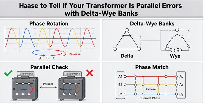
Phase rotation and parallel errors with delta-wye banks occur when two transformers on the same bus disagree on phase sequence, vector group, or polarity — and even a 30° phase displacement can drive circulating current to roughly 5× the rated load, so verify phase angle, rotation, and vector group before closing any tie breaker.
If you’ve ever watched a new delta-wye transformer refuse to parallel with an existing one — or seen the tie breaker trip the instant it closes — you know how expensive that silence is. This guide walks through why phase rotation and parallel errors show up with delta-wye banks, what they actually do to your equipment, and the exact checks that keep them from happening. It’s written for the people who buy, specify, and commission these units: EPC procurement leads, plant engineers, and anyone ordering a spare transformer from overseas.
What you’ll take away
- A delta-wye connection already carries a 30° phase shift — that’s normal, but it decides who you can parallel with.
- Three separate things cause parallel errors: wrong phase rotation, wrong vector group, and flipped polarity.
- A 30° mismatch isn’t a “small” problem. It can push circulating current to roughly 5× the rated load before you’ve connected any load.
- There’s a repeatable pre-energization checklist that catches every one of these on the bench.
- If you buy from a different region than you operate in, the Dy1-vs-Dyn11 convention gap can land a “matching” spare 60° out of phase.
Why a Delta-Wye Bank Already Has a 30° Shift Built In
A delta-wye (Δ-Y, or Dyn) transformer doesn’t just change voltage — it rotates the secondary waveform by 30 electrical degrees relative to the primary. That’s not a defect. It’s a direct result of the geometry: on the wye side, the line-to-line voltage is the vector sum of two phase voltages, and that subtraction lands the line voltage 30° off the phase voltage. The delta side has no such offset, so the two ends of the transformer sit 30° apart.
The clock face, in plain terms
Engineers label this with a clock number. One hour on the clock = 30°.
- Dy1 (North American practice): secondary lags primary by 30° (1 o’clock).
- Dyn11 (IEC / most of the world): secondary lags primary by 330°, which is the same as leading by 30° (11 o’clock).
- Yd1 / Yd11: same idea, but the delta is on the low-voltage side.
The neutral marker matters too. “Dyn11” means the wye neutral is brought out; “Dy11” means it isn’t. For a four-wire LV system, you want the “n.”
Why 30° is fine alone but fatal in parallel
Run one delta-wye transformer by itself and nobody cares about the 30°. The load sees a clean voltage. The trouble starts when a second transformer ties onto the same bus. For two sources to share a bus, their secondary voltages have to line up phase-for-phase. If one sits 30° (or 60°) off the other, you haven’t connected two supplies — you’ve built a low-impedance loop between two out-of-phase voltages, and current rushes around it.
The Three Ways a Parallel Goes Wrong
Most parallel failures with delta-wye banks trace back to one of three mismatches. They’re independent, but they stack.
1. Phase rotation (ABC vs ACB)
Phase rotation is the order the phases reach peak: A-B-C (positive) or A-C-B (negative). Swap any two line conductors and you flip it. A reversed rotation won’t change the line-to-line voltage magnitude, so a quick voltmeter check misses it entirely — but it will spin three-phase motors backward and, if you close a tie between two sources of opposite rotation, it can hammer the bus with fault-level current.
In North America the utility default is A-B-C counter-clockwise. If your new unit was built or tested to the opposite sequence, it has to be corrected at the high-voltage bushings — not by twisting the low-side leads, which does nothing to the rotation through the transformer.
2. Vector group mismatch (Dy1 beside Dyn11)
This is the quiet one. Two transformers can both be “delta-wye” and still be incompatible. Dy1 and Dyn11 are only two clock positions apart, which is a 60° phase displacement. Put them on the same bus and the voltage between corresponding phases is a full rated voltage apart — closing the tie is effectively closing a switch on a short circuit.
You can sometimes fix it by swapping two phases on either the HV or the LV side of one unit (not both — doing both flips you 180° the wrong way). But that’s a field correction, not a substitute for ordering the right group.
3. Polarity: the additive/subtractive 180° trap
Single-phase units in a bank, or a replacement transformer, can be additive or subtractive polarity. In a delta-wye transformer, switching from one to the other physically moves the X1 bushing and flips the vector group from Dy1 to Dyn11 — another 30° to 60° of grief. On a single-phase unit, reversed polarity puts the secondary 180° from where it should be. Alone, the load may still get voltage; in parallel, it opposes the other unit and circulates current limited only by impedance — many times rated, even with no load.
Never trust the nameplate alone here. IEEE C57.12.00 is explicit that field verification of phase relationships is mandatory before closing paralleling switches, because nameplate data doesn’t always reflect the actual winding connection.
What a Mismatch Does — Circulating Current, by the Numbers
Here’s the part that convinces people to do the checks. Take two 1,000 kVA units, 480 V secondary, 5.5% impedance — a standard illustrative case based on IEC 60076-8 paralleling guidance:
| Situation | Angle between secondaries | Circulating current (vs rated)* | What shows up |
| Same group (Dyn11 + Dyn11) | 0° | ~0 (load current only) | Clean parallel |
| 30° group difference | 30° | ~4.7× rated, no load yet | Warm transformers, relay trips |
| 60° apart (Dy1 next to Dyn11) | 60° | ~9× rated | Near short-circuit at the breaker |
*Voltage between corresponding phases = 2 × V × sin(θ/2); divide by total impedance. Figures are illustrative for the example above, not a substitute for your own calculation.
The point isn’t the exact number — it’s that the current is enormous before a single amp of load flows. That’s why a “looks close enough” approach to paralleling burns equipment.
Your Pre-Energization Checklist
Run this before you close any tie breaker between two delta-wye sources. De-energize and lock out first; this is verification work, not live tuning.
- Read both nameplates. Vector group (Dy1 / Dyn11 / Yd…), voltage ratio, polarity, phase rotation, impedance. Write it down.
- Confirm voltage ratio matches within about 0.5% at the no-load secondary.
- Confirm vector group is identical (or deliberately compensated). “Delta-wye” is not enough — the clock number has to agree.
- Check phase rotation on both secondaries with a phase rotation meter. Same sequence (A-B-C or A-C-B) on both.
- Measure between corresponding terminals (H1–H1, X1–X1, etc.). You want near-zero volts — under ~5 V on low-voltage banks.
- Confirm phase-to-neutral voltages match the expected wye values.
- Verify impedance is within ~7.5% of each other (IEEE C57.12). Mismatch won’t stop paralleling but it decides who carries the load.
- Recheck differential relay (87T) settings so the corrected phase relationship doesn’t read as a fault and trip you offline.
If any reading looks wrong, stop. De-energize, trace the conductors, and repeat with a second meter. Closing on a bad phasing check is how transformers get wrecked.
The Cross-Border Trap: Dy1 in North America, Dyn11 Almost Everywhere Else
This is the one that bites buyers. A specification that says only “delta-wye” tells the supplier nothing about the clock number. A North American utility standardizes on Dy1; most of Europe, Asia, the Middle East, and Africa standardize on Dyn11. Order a “delta-wye” spare from a shop that builds to the other convention and your “matching” unit arrives 60° out of phase with the bank it’s meant to back up.
The fix is boring and free: write the full symbol in the enquiry. “Dyn11,” not “delta-wye.” Add the neutral requirement, the phase sequence, and the clock number. Those six characters cost nothing at quotation stage and can’t be corrected later without a factory reconnection and a fresh test.
If you’re procuring across regions, have the supplier translate their factory notation into your project’s approved phasor drawing. Don’t rely on terminology — prove the voltages line up at the bus tie.
How to Spec a Delta-Wye Bank That Plays Nice with the Bus
When you write the RFQ, treat the vector group like you treat kVA and voltage — it’s a primary specification, not a manufacturer detail. At minimum, state:
- Exact vector group with clock number and neutral (e.g., Dyn11).
- Required phase rotation (A-B-C).
- Voltage ratio tolerance and tap positions.
- Impedance and its allowed spread.
- Confirmation that the unit is built for parallel operation with the existing bank.
A good supplier will push back on a blank vector-group column instead of quietly building to their default. That pushback is the cheapest insurance you’ll get. If you’re matching an existing installation and aren’t sure of its group, send the nameplate and single-line diagram to the factory and let their engineers confirm compatibility before you order — it saves a wrong shipment and a site standstill. (As covered earlier, the pre-energization checklist above is your last line of defense even after a clean factory test.)
Key Takeaways
- Every delta-wye bank carries a 30° shift by design; paralleling depends on the other unit carrying the same shift.
- Parallel errors come from three independent sources: phase rotation, vector group, and polarity.
- A 30° mismatch drives circulating current to several times rated load — before any load is connected.
- Verify ratio, vector group, rotation, terminal voltages, and impedance on the bench before closing the tie.
- Write the full vector-group symbol (Dyn11, not “delta-wye”) in every cross-border RFQ.
- Field checks beat nameplate trust — IEEE and IEC both require verification before paralleling.
Frequently Asked Questions
Q: Can you parallel a delta-wye transformer with a wye-delta transformer? A: Only if their vector groups are engineered to match. A plain Δ-Y and a plain Y-Δ both carry 30°, but in opposite directions, so their secondaries sit 60° apart — paralleling them without correction is a short circuit at the breaker. Match the clock number, don’t just match the letters.
Q: Why can’t I just swap two primary wires to fix a 30° phase shift? A: Swapping primary phases changes the phase rotation (ABC to ACB) but does not remove the 30° angular displacement caused by the winding or polarity difference. You fix that by interchanging the secondary bushings (X1/X2) or by swapping two phases on one side only — never both.
Q: What’s the difference between Dy1 and Dyn11? A: They’re both delta-primary, wye-secondary, but Dy1 lags the primary by 30° (North American convention) and Dyn11 leads by 30° (IEC, used in most of the world). Two clock positions apart = 60° displacement, so they are not directly parallel-compatible.
Q: How close do the impedances have to be to parallel transformers? A: Within about 7.5% of each other per IEEE C57.12. A mismatch won’t stop them running together, but the lower-impedance unit picks up more than its share of the load and can overload while its partner runs light.
Q: Do I still need a field phasing check if the factory acceptance test passed? A: Yes. The FAT proves the transformer was built right; it doesn’t prove the site cables, labels, and switchgear phase identification were installed right. Always verify at the actual bus-tie point before closing.
Q: What does a polarity error do in a delta-wye bank? A: It can flip a single-phase unit’s secondary 180°, or shift a three-phase unit’s vector group by 30–60°. In parallel, that drives a circulating current limited only by impedance — many times rated, even with no load — and can trip protection or overheat windings.