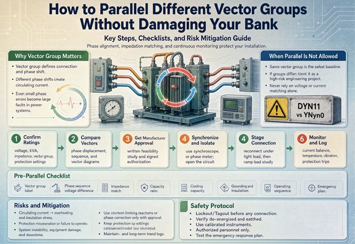
You can parallel transformers with different vector groups only when the clock numbers differ by four or eight. Those differences are 120 and 240 degrees, and rolling the three conductors one position cancels them. Every other difference needs a factory reconnection or a different transformer. The arithmetic below tells you which case you are in and what each fix costs.
“Bank” cuts two ways here. A bank of transformers is the pair or trio sharing a bus. A bank account is what pays for the mistake. This article keeps both in view, because the technical answer and the money answer are the same answer, and they are decided at different times. One gets decided on a drawing. The other gets decided when somebody closes a tie breaker at 2 a.m. and the lights go out.
Most pages on this subject stop at “the vector groups must match.” That is true and useless. You already know they do not match, otherwise you would not be reading this. The useful question is narrower. Which mismatches can a crew of two fix in an afternoon with cable and a torque wrench, which ones need the unit to go back to a factory, and which ones mean the transformer you bought is the wrong transformer. Those three answers have very different price tags, and they are separated by simple arithmetic.
The Answer in One Table
Start with the number you can read off the nameplate tonight. Subtract the two clock numbers, take the absolute value, and if the result is above six, subtract it from twelve. What remains is the angle in clock hours, and each hour is 30 degrees. The table below runs that out on a 480 V bus with two 1,000 kVA units at 5.75 percent impedance.
| Clock difference | Phase angle | Volts across the open tie | Circulating current | Can a wrench fix it | Cheapest route |
|---|---|---|---|---|---|
| 0 | 0 degrees | 0 V | 0 | Already parallel | Close the tie |
| 1 or 11 | 30 degrees | 248 V | 4.50 times rated | No | Factory reconnection or a new unit |
| 2 or 10 | 60 degrees | 480 V | 8.70 times rated | No | Factory reconnection or a new unit |
| 3 or 9 | 90 degrees | 679 V | 12.30 times rated | No | Factory reconnection or a new unit |
| 4 or 8 | 120 degrees | 831 V | 15.06 times rated | Yes | Roll three conductors, one outage |
| 5 or 7 | 150 degrees | 927 V | 16.80 times rated | No | Factory reconnection or a new unit |
| 6 | 180 degrees | 960 V | 17.39 times rated | No | Factory reconnection or a new unit |
Two rows in that table are worth staring at, because they invert what most people expect.
The 120 degree row is the only fixable one, and it is the second largest voltage on the list. The 30 degree row is the smallest mismatch on the list, and it is the one that destroys transformers. The 60 degree error is louder, faster, and usually harmless to the hardware. The 30 degree error is quiet, slow, and expensive. If you remember one thing from this page, make it that inversion, because every instinct you have about “bigger difference, bigger danger” points the wrong way.
The rest of this article is the working-out.
Why the Clock Number Stops a Tie From Closing
A vector group code does two things at once. The letters tell you how each winding is connected. The number tells you where the low side sits relative to the high side, in half-hour steps on a clock face.
For parallel operation only the second part matters. Two transformers feeding one bus have to present the same voltage at the same angle at the same instant. If unit A puts its A phase at zero degrees and unit B puts its A phase at thirty degrees, the bus does not average them. It connects them, and the difference between those two voltages drives a current through the only thing in the loop, which is two leakage impedances.
That is the whole mechanism, and it is worth putting numbers on because the numbers are rude.
The driving voltage for a displacement of delta between two equal magnitudes is twice the sine of half the angle. At 30 degrees that is 0.5176 per unit. At 60 degrees it is a full 1.0 per unit. At 180 degrees it is 2.0, and the loop current is exactly the bolted fault current of one unit, which is one over the impedance, forever, with the breakers closed.
Divide by the sum of the two impedances and you have the current. Two 1,000 kVA units at 5.75 percent each give 0.115 per unit of loop impedance, so 30 degrees produces 4.50 times rated current before a single amp of load is connected.
The number on the nameplate is a phasor, not a label
Here is the part that gets lost in procurement. Dyn11 and Dyn1 differ by two characters and one digit, they describe machines of the same kVA, the same voltage, the same impedance, the same price, and they cannot be connected to each other.
The reason is regional, and it is not a standard-versus-standard fight. North American practice settles on delta-wye with the low side lagging the high side by 30 degrees, which is clock 1. IEC practice settles on the low side leading by 30 degrees, which is clock 11. Both are correct. Both are called “delta-wye” on a single line diagram. Put one of each on the same bus and you have a 60 degree error, 480 volts of driving voltage, and 8.70 times rated current.
This is the single most common way a project ends up with two units that cannot be paralleled, and it does not happen because anyone was careless. It happens because the drawing said “delta-wye” and both suppliers built what that phrase means in their own market. Six extra characters on the drawing, Dyn1 instead of delta-wye, would have prevented the entire problem, and they cost nothing at quotation stage.
What 248 volts does to two windings
Take the 30 degree case, because it is the one that will actually happen to you.
Two 1,000 kVA units, 480 V, 5.75 percent. Rated current is 1,202.8 amps. The circulating current is 4.50 per unit, or 5,414 amps, and it flows in a loop between the two secondaries with nothing connected downstream.
Current squared is the heat. 4.50 squared is 20.26, so a unit with 9,000 watts of load loss at rating is now dissipating 182.3 kilowatts of copper loss. Add the 1,500 watts of core loss and the tank is rejecting 183.8 kilowatts instead of 10.5, which is 17.5 times its design heat load.
The oil does not care that the current is circulating rather than doing useful work. It heats at the same rate either way.
| Quantity | At rated load | At 30 degree circulating current |
|---|---|---|
| Secondary current | 1,202.8 A | 5,414 A |
| Copper loss | 9,000 W | 182,300 W |
| Total heat into the tank | 10,500 W | 183,800 W |
| Ultimate top oil rise | 55 K | about 543 K |
| Time for top oil to reach 105 C | hours | 19.4 minutes |
| Time for the winding hot spot to pass 180 C | never | 2.6 minutes |
The hot spot row is the one that matters. At rated load in a 30 C room, the hot spot sits near 108 C. The limit for 65 degree rise insulation is 180 C. Under 4.5 times rated current the hot spot gradient, which is 23 K at rating, climbs toward 255 K, and it covers the 72 K it needs to reach the limit in under three minutes.
Two minutes and thirty-six seconds. That is not a slow degradation story. That is the window you have to open a breaker.
The thirty degree error is the one that hides
Now the uncomfortable part. Nothing trips in the first cycle.
The transformer’s own primary protection is set at 125 percent of rated current, which on a 13.8 kV primary is a 60 amp device for a 1,000 kVA unit. Four and a half times rated current is 188 amps on that primary. The instantaneous element is somewhere around 600 amps. It does not pick up, because 4.5 per unit does not look like a fault from the high side. It looks like load.
The differential relay is also silent, and it is silent correctly. Current leaves one secondary and enters the other, ampere-turns balance on both sides of both units, and each differential zone sees a balanced through-current. There is no differential current because nothing is faulted. The relay is doing its job.
What eventually operates is the low voltage main, and it operates on long time. A 3,000 amp frame seeing 5,414 amps is at 1.8 times its rating, which lands in the long-time band and opens somewhere in the one to three minute range depending on the settings. That is roughly when the winding hot spot has been above its insulation limit for a minute.
So the sequence is this. Tie closes, no bang, no flash, no alarm. Somebody says it looks fine. Between one and three minutes later the main trips with no load on the bus. The natural diagnosis is a bad breaker, or a bad trip unit, or a nuisance setting. The natural response is to raise the setting and try again.
The second close is where the transformer dies. The first close put it at the edge of its thermal limit for a minute. The second close, at a higher setting, holds it there for four or five minutes, and now you are buying a transformer instead of resetting a breaker.
Why the sixty degree error is the safer one
Put a Dyn1 next to a Dyn11 and the numbers get bigger and the outcome gets better.
Sixty degrees gives a driving voltage of 1.0 per unit, which is 480 volts across the tie, and a circulating current of 8.70 per unit. That is 10,459 amps on a 480 V bus. A 3,000 amp main sees 3.5 times its rating and goes instantaneous in two or three cycles.
You get an arc, a very loud noise, a tripped main, and a plant full of people standing in the dark asking what happened. What you usually do not get is a damaged transformer, because the event is over in 40 milliseconds. The mechanical forces at 8.7 per unit are 75 times rated, and the windings are built for a through-fault at 17.4 per unit, so there is margin. The thermal duty is 40 milliseconds against a two second rating, so there is a lot of margin.
That is the inversion. The 60 degree error is a commissioning embarrassment with a scary noise. The 30 degree error is a slow failure that produces a plausible wrong diagnosis, a second attempt, and a purchase order.
If you have to have a mismatch, hope for a big one. Nobody ever closed a 60 degree tie twice.
Where the money actually goes
The transformer is not usually the biggest line item in this failure.
Two 1,000 kVA units at roughly $31,000 each is $62,000 to replace. Switchgear inspection and repair after an arc event runs $15,000 to $20,000 if the bus bars are sound and the breakers only need dressing. The downtime is the rest, and it dwarfs both. At $9,000 an hour, three days is $648,000.
Which is why the interesting number in the table at the top of this page is not the circulating current. It is the cost of the fix, and the reason the cheapest fix on the list costs nothing at all. It is a line on a drawing, written before the purchase order, and it expires the moment the order is placed.
The Only Three Ways Three Conductors Can Land
Here is the question that decides whether your problem is a work order or a purchase order. Given two transformers with different clock numbers, is there any arrangement of the six conductors at the tie that makes the phasors line up?
There are six ways to land three conductors on three terminals. Three of them are cyclic, meaning every conductor moves the same number of positions. Three of them are transpositions, meaning two conductors trade places. Those two families behave completely differently, and the difference is the entire subject of this article.
| Arrangement | What it does to the phasor set | Rotation delivered | Verdict |
|---|---|---|---|
| a-b-c, no change | Shifts by 0 degrees | ABC | Works when the clocks already match |
| Roll one position | Shifts by plus 120 degrees | ABC | Works when the clocks differ by 4 |
| Roll the other way | Shifts by minus 120 degrees | ABC | Works when the clocks differ by 8 |
| Swap a and b | Mirrors the set | ACB | Nothing lines up |
| Swap b and c | Mirrors the set | ACB | Nothing lines up |
| Swap a and c | Mirrors the set | ACB | Nothing lines up |
A cyclic arrangement rotates the whole set of three phasors by a fixed angle and leaves the phase rotation alone. That is exactly what you need, because a rotation is the only operation that can undo a rotation. A transposition does something else. It reflects the set, which reverses the direction the phases go round, and no amount of reflecting turns a mirrored set into the original one.
So the fixable differences are the ones that are multiples of 120 degrees. In clock hours, that is zero, four and eight. Everything else, which is thirty, sixty, ninety, one hundred fifty and one hundred eighty degrees, cannot be reached by moving conductors around.
That is where the field rule comes from. Every old handbook that says “units differing by four or eight clock positions may be paralleled after cyclic permutation of the connections” is describing this arithmetic without showing it. It is not a convention and it is not a rule of thumb. It is the complete list of angles that a permutation can produce.
One consequence that surprises people
The rule includes a case nobody thinks of as a mismatch. A difference of eight clock hours is 240 degrees, which is the same as minus 120. So a Dyn11 and a Dyn3 are fixable, and a Dyn11 and a Dyn7 are fixable, because eleven minus three is eight and eleven minus seven is four. Both of those pairs look like a disaster on paper and both are an afternoon of work.
Meanwhile a Dyn11 and a Dyn5, which look like close cousins and are both common, differ by six, which is 180 degrees, and are not fixable at all. That is the pair that catches people, because 11 and 5 feel adjacent. They are not. They are opposite.
A quick sanity check that costs nothing. Take the two clock numbers, subtract, and look at the answer. If it is 0, 4 or 8, you have a chance. If it is 2, 6 or 10, you do not, because those are the even differences that are not multiples of 120. If it is odd, you do not either, and you did not need to read this far.
Rolling the Conductors: What It Involves
The operation is simpler than its reputation. You move three conductors one position, in the same direction, on one side of one transformer. That is it.
The detail is in the choice of side and the paperwork around it.
Roll on the low voltage side when you can, because the conductors are shorter, the clearances are smaller, and the labour is cheaper. Roll on the high voltage side when the low side is a formed busbar that cannot be re-routed, which happens more often than people expect on a unit that lands directly into a switchboard throat.
Do not roll the neutral. The neutral point is common to all three phases and does not rotate. If the unit has a neutral brought out and bonded at the transformer, that bond stays exactly where it is, and the phase-to-neutral voltages stay balanced after the roll. This is the part that makes the operation safe. You are relabelling which bus phase each winding feeds, not changing the winding.
What the relay sees after a roll
If the current transformers sit on the transformer bushings, the differential zone does not care about the roll at all. The 87T compares the high side CT set to the low side CT set, both of which are upstream of the conductors you moved, and the through-current stays balanced. Nothing in the differential settings changes, and that is the good news.
What does change is the meaning of a phase label. The CT that the relay calls A is now feeding bus phase C. For differential protection that is invisible. For everything else it is not:
| Function | Affected by the roll | What to do |
|---|---|---|
| Transformer differential, 87T | No, if CTs are on the bushings | Nothing |
| Phase overcurrent, 50/51 | Yes, the label follows the conductor | Update the panel schedule and SCADA point names |
| Metering and power factor | Yes | Re-label, or the reports will show a phase shift that is not there |
| Phase-to-phase coordination with the tie | Yes | Re-run the coordination for the new phase mapping |
| Cable-mounted CTs | Yes, they must move with the conductors | Roll the CTs, not just the cable |
| Neutral or ground CT | No | Nothing |
The cable-mounted case is the one that bites. A set of CTs installed around the cables at the switchgear end stays with the cable when the cable moves, so if you roll the conductors and leave the CTs, the relay now associates the wrong current with the wrong phase. That produces exactly one symptom: a differential or directional element that misoperates on external faults and behaves perfectly on internal ones. It is a miserable thing to troubleshoot.
The drawing is part of the job
Three documents have to change before the crew leaves site, or the next crew will undo your work.
The single line diagram gets the new conductor mapping. The terminal box gets a durable label saying which terminal now lands on which bus phase. The commissioning record gets the measured voltages from before and after.
Sites that skip this step have a predictable future. Somebody opens the terminal box in four years, sees three conductors landed in an order that contradicts the drawing, “corrects” it, and closes the tie. The transformer that was fine for four years is now a 30 degree error with a fresh set of fingerprints on it.
The physical constraint nobody budgets for
Rolling is easy on paper and sometimes impossible in a tray.
Three parallel runs of 500 kcmil in a cable tray have very little slack. Moving each conductor one lug position requires the lug to reach a terminal that may be 6 or 8 inches away, and cable does not stretch. In practice the crew either re-terminates with longer barrels, adds a splice, or re-routes a section of tray. On a formed busbar it is worse, because the bar is bent for one landing pattern and a new pattern means new bar.
This is why the cost of a roll is not the cost of the labour. It is the cost of the labour plus whatever the conductors need to reach their new homes, and on a 480 V tie with 500 kcmil that is usually a few thousand dollars of material.
The Mirror Trap: Why Swapping Two Leads Does Not Work
Now the part that will save somebody a transformer.
Search any forum for “parallel different vector groups” and you will find the same advice repeated with confidence. Swap two leads on one side and the clock number moves by six. Swap two on both sides and it moves by twelve, or in some versions it moves by nothing, depending on who is typing. A surprising number of people have done this, and a smaller number have done it and lived.
Both versions are wrong, and the reason is worth two minutes.
A transposition does not rotate the phasor set. It reflects it. The three voltages are still 120 degrees apart and still the right magnitude, but they now go round in the opposite direction. That set cannot equal the original set at any angle, because the original set goes round one way and the reflected set goes round the other. There is no rotation that fixes a reflection.
It gets worse, because a reflection does not look obviously wrong on a voltmeter. Measure it pole by pole and you get a pattern that is easy to misread.
| Pole measured | True 30 degree error | Mirrored 30 degree set |
|---|---|---|
| A to a | 248 V | 480 V |
| B to b | 248 V | 960 V |
| C to c | 248 V | 480 V |
A uniform error reads the same voltage on all three poles. A mirrored set reads two poles one way and the third pole at double. That 960 volt reading on the middle pole is the signature, and it is the single most useful diagnostic in this article, because it is the one measurement that tells you the difference between a 30 degree problem you might fix and a rotation problem you cannot.
If you swap two leads and then measure 480, 960, 480, you have not moved the clock by six. You have reversed the rotation on that unit. Motors fed from it will run backwards, and it still will not parallel with the other unit.
The version where both sides get swapped
The other piece of folklore says you swap two leads on the high side and two on the low side, and the two operations combine to give you a 180 degree shift.
Run the algebra and the two operations cancel. Relabelling the incoming supply and relabelling the outgoing conductors are inverses of each other, so the phase relationship at the bus comes out exactly where it started. Nothing changes except which terminal is called A. If a crew reports that this worked, what they actually did was reconnect something inside the tank, or they were paralleling two units that already matched.
The industrial literature is not much help here, because at least one widely copied technical note describes a 180 degree conversion by “swapping R and B on both sides.” The case study in the same note quietly mentions that the transformer was internally reconnected at the factory, which is the part that did the work. The lead swap was decoration.
What an internal reconnection actually is
Every transformer has an internal connection between coil sections, and on some designs those connections are brought to a link board that can be changed. Changing them is a factory operation, because it means opening the tank or the enclosure, breaking a brazed or bolted joint, re-making it in a different pattern, and then re-running the ratio and phase displacement tests to prove what you built.
On a distribution class unit, this usually is not offered. The windings are wound for one connection and the links are not accessible. On larger power transformers, and on units built with a tap link board for dual voltage, it sometimes is, and the manufacturer will quote it. Ask before you assume, and ask before the unit ships, because the price triples afterward.
Reading the Voltmeter Before You Close Anything
The commissioning test is not complicated and almost nobody does it properly.
You need both units energized from their own sources, the tie breaker open, and a voltmeter with a range above the system voltage. Measure between corresponding terminals across the open tie: A to a, B to b, C to c. Then measure each phase to neutral on both sides.
The expected result is zero on all three phase pairs. Anything else is an angle, and the angle is computable from the reading.
The relation is the same one that produced the table at the top of this page, run backwards. The measured voltage is twice the line voltage times the sine of half the angle, so the angle is twice the arcsine of the measured voltage divided by twice the line voltage. At 480 volts, the readings map like this.
| Reading, pole to pole | Implied angle | What it means | What to do |
|---|---|---|---|
| 0 V on all three | 0 degrees | Groups match, ratio matches | Check impedance and grounding, then close |
| 125 V on all three | 15 degrees | Half a clock step, usually a tap position | Match the taps |
| 248 V on all three | 30 degrees | One clock step | Stop. No permutation fixes this |
| 480 V on all three | 60 degrees | Two clock steps, the ANSI versus IEC case | Stop. No permutation fixes this |
| 679 V on all three | 90 degrees | Three clock steps | Stop |
| 831 V on all three | 120 degrees | Four clock steps | Roll one conductor, then re-measure |
| 927 V on all three | 150 degrees | Five clock steps | Stop |
| 960 V on all three | 180 degrees | Six clock steps | Stop |
| 480, 960, 480 V | Not an angle | Mirrored set, rotation reversed | Undo the lead swap |
| Unequal but not the mirror pattern | Not an angle | Wiring error downstream of the transformer | Trace the conductors |
Two habits make this test worth doing.
Measure all three poles, always. One reading tells you nothing about whether the set is uniform, and the mirror pattern is the case where a single reading is actively misleading. The person who measures one pole, sees 480 volts, and concludes “60 degrees” has a fifty percent chance of being wrong about the nature of the problem.
Record the readings with the date, the meter serial number, and the tap positions of both units. When the tie is closed two years later by a different crew, that record is the only evidence that the system was ever verified.
The neutral check people forget
Phase-to-neutral is where a wrong neutral landing hides.
On a 480Y/277 system, phase to neutral should read 277 volts on all three phases of both units, and zero between the two neutrals. If one unit reads 277, 277, 277 and the other reads 480, 480, 0, the second unit’s neutral is not where you think it is.
Two neutrals at different potentials is not an angle problem and it is not fixed by any of the methods above. It usually means one unit is grounded at the transformer and the other is grounded at the service, or that a neutral conductor was landed on a phase terminal. Both are wiring errors, both are dangerous, and both are found in thirty seconds with a voltmeter if anybody thinks to measure it.
What a Roll Does Not Fix
A successful roll solves the angle. It solves nothing else, and the other four conditions still have to be checked before the tie closes. This is where projects that “fixed the vector group” discover they are not done.
| Condition | Still true after a roll | Consequence if it is wrong |
|---|---|---|
| Voltage ratio and tap position | Unchanged | Circulating current at all times, proportional to the ratio error |
| Percent impedance | Unchanged | Uneven load sharing, one unit at rating while the other is at 70 percent |
| Phase sequence | Unchanged | Effectively a short between phases on closing |
| Neutral and grounding arrangement | Unchanged | Ground fault current and coordination both wrong |
None of these is fixed by moving conductors, and all four are cheaper to check than to discover. The next two sections run the numbers on each, because in practice the angle is the dramatic problem and the other four are the expensive ones.
What Each Route Costs
Seven routes exist. Only one of them is free, and it is the only one that is no longer available once the purchase order is signed. The rest are ordered by price, and the ordering is not what most people guess.
| Route | Cost, 1,000 kVA class | Time | What you get | What you give up |
|---|---|---|---|---|
| Specify the clock number at quotation | 0 | 0 | The right unit | Nothing, if you do it before the PO |
| Factory reconnection before shipment | $2,400 | 2 weeks | The group you need | Two weeks of schedule |
| OEM field reconnection after delivery | $13,000 | 3 weeks | The group you need | Warranty cover and three weeks of site time |
| Roll three conductors on site | $4,800 | One outage window | A 120 or 240 degree error removed | Nothing, if the conductors reach |
| Buy a matching unit | $31,000 | 20 weeks | A unit that parallels | The old unit becomes a spare that does not match |
| Phase shifting transformer | $62,000 | 30 weeks | Any angle you want | Twice the price and a permanent loss penalty |
| Never close the tie | 0 | 0 | Nothing fails | The redundancy you built the second unit for |
The free route, and why it expires
Six characters on a drawing. That is the entire cost of avoiding this article.
The catch is timing. Once the core is wound and the tank is closed, the clock number is a physical property of the machine, and changing it is a factory job with a price. Before that point it is a line on a works order. The same change that costs $13,000 after delivery costs about $2,400 before shipment, and costs nothing at all if it is caught at quotation, because the manufacturer is building to your drawing either way.
The cheapest possible intervention is a two-line email. “Confirm the vector group is Dyn11, not Dyn1. Confirm the clock number in writing on the datasheet, not just the winding letters.” Suppliers answer that question honestly and immediately, because it is a build instruction, not a negotiation.
The expensive version of the same email is the one sent after the unit arrives, which reads “we need to talk about the vector group.”
Factory reconnection before shipment
If the unit is built and the group is wrong, the manufacturer can usually still fix it before it ships. On a distribution unit this means re-landing the low voltage leads inside the tank or the enclosure, re-running the ratio test and the phase displacement test, and reprinting the nameplate.
Budget about $2,400 and two weeks on a 1,000 kVA unit. Larger units and cast resin designs cost more, because the connections are less accessible and the test protocol is longer.
The important thing to ask for is the test evidence. A reconnected unit should arrive with a new routine test report showing the ratio and the phase displacement, measured, not asserted. If the report is the original one with a new date, you have bought a nameplate, not a transformer.
Field reconnection after delivery
This is the same work done at your site, and it costs five times as much for reasons that have nothing to do with the winding.
Oil-filled units need the oil handled, which means a vacuum truck, a test on the oil before and after, and a period of standing before re-energization. Cast resin units cannot be opened at all in most designs, so “field reconnection” on a cast unit usually means the unit goes back. Add crane time, freight in both directions, a factory test, and the site labour, and $13,000 is not an unreasonable number for a 1,000 kVA class unit.
There is also a warranty question that nobody raises until later. A reconnection done by the OEM keeps the warranty. A reconnection done by a third party service shop usually does not, and the manufacturer will say so in writing if asked.
Rolling the conductors
Four thousand eight hundred dollars, one outage window, and the constraint that the clock difference has to be four or eight.
The money is cable, lugs, splices if the runs are short, labour for two electricians and a helper, and the testing afterward. The outage is six to twelve hours if the conductors reach and two days if they do not.
This is the best value on the list by a wide margin, and it is available in maybe one case in six. If your difference is 120 or 240 degrees, stop reading and go measure the cable slack.
Buying a matching unit
Thirty-one thousand dollars and twenty weeks, and the twenty weeks is the part that hurts.
A new unit is the right answer when the old one is at the end of its life anyway, when the mismatch is 30 or 60 degrees, and when the project can absorb a lead time. It is the wrong answer when the reason you are reading this is that a unit already arrived and the schedule is already tight.
There is a second cost that does not show up in the quote. The unit you cannot parallel becomes a spare, and a spare that does not match the rest of the bank is not a spare. It is a very heavy paperweight with a nameplate.
The phase shifting transformer
Sixty-two thousand dollars, thirty weeks, and roughly twice the losses of the unit it sits beside.
A phase shifting transformer, or a paraline, inserts a controlled angle between two systems. It is the correct answer in exactly one situation: when neither unit can be changed. That means utility transmission, where a 200 MVA generator step-up unit cannot be reconnected and cannot be replaced, and the angle between two networks has to be managed continuously.
At distribution scale it is almost never justified, because a transformer with the right clock number costs half as much and has no angle to manage. People ask about it because it sounds like a clever workaround. It is a clever workaround for a problem that has a cheaper solution.
Never closing the tie
Zero dollars and zero weeks, and it is what most sites actually do.
Two transformers, two buses, a tie breaker that stays open and interlocked. Everything works. The plant has two sources. What it does not have is the ability to transfer load from one to the other, which is usually the entire reason the second transformer exists.
The honest framing is that this option converts a transformer problem into a redundancy problem. If the load is split 60/40 and one unit fails, the other cannot pick up the difference. If the load is split 50/50 and both units are needed for normal operation, a single failure takes down half the plant.
Sometimes that is acceptable. A plant with a 40 percent peak and two units at 60 percent each has margin to spare, and an open tie costs nothing but a line on the operating procedure. A plant at 85 percent does not have that luxury, and the open tie is a slow-motion capacity problem.
The twenty year view
Run the two realistic options against each other over twenty years.
Rolling costs $4,800 once and changes nothing else. The pair runs at the same losses, the same capacity, the same everything, with the angle gone.
Replacing costs $31,000 plus twenty weeks, and it buys a unit that matches. It does not buy efficiency, because you are replacing a perfectly good transformer with an identical one that happens to be wound differently. The difference is $26,200, which at a 7 percent discount rate over twenty years is $2,473 a year of pure carrying cost for a connection you could have made with cable.
That comparison flips when the existing unit is old, when the impedance mismatch is also bad, or when the roll is physically impossible. It does not flip on the basis of the vector group alone.
The Other Four Conditions, With Numbers
Once the angle is settled, four more things have to be true. Each of them has a number attached, and the numbers explain why “the vector groups match” is a starting condition rather than an answer.
Ratio and tap position: one step is ten percent
Two units with matching groups but different output voltages circulate current continuously, and the current does not depend on load. It depends on the ratio error divided by the sum of the impedances.
At 5.75 percent each, the sum is 11.5 percent, so the circulating current in per unit is the ratio error divided by 0.115.
| Ratio error | Circulating current | Amps on 1,000 kVA | Copper loss added |
|---|---|---|---|
| 0.5 percent | 4.3 percent | 52 A | 17 W |
| 1.0 percent | 8.7 percent | 105 A | 68 W |
| 1.25 percent | 10.9 percent | 131 A | 106 W |
| 2.5 percent | 21.7 percent | 261 A | 425 W |
| 5.0 percent | 43.5 percent | 523 A | 1,701 W |
One tap step on a standard distribution unit is 1.25 percent, which is 10.9 percent of rated current doing nothing but heating copper. Two steps is 21.7 percent. That is why the tap positions of both units have to be identical, and why “we will match them later” is not a plan. The taps are matched before the tie closes or they are not matched at all.
The loss numbers look small, and they are, which is the trap. A hundred and six watts will never trip anything. What it does is consume 10.9 percent of the unit’s capacity and make the no-load loss test look wrong during commissioning, which sends people looking for a core problem that does not exist.
Impedance: three hundred kVA that you paid for and cannot use
Load divides in inverse proportion to impedance, measured on a common kVA base. Both units at 5.75 percent share in proportion to their ratings, so a 1,000 and a 750 both reach rating at the same total load of 1,750 kVA. Perfect.
Change the small unit to 4.0 percent and the sharing changes, because the smaller unit now has the lower impedance and takes more than its share.
| Pair | Total at which the first unit reaches rating | Usable share of installed capacity | Capacity stranded |
|---|---|---|---|
| 1,000 at 5.75% plus 750 at 5.75% | 1,750 kVA | 100 percent | 0 |
| 1,000 at 5.75% plus 750 at 4.0% | 1,445 kVA | 82.6 percent | 305 kVA |
| 1,000 at 5.75% plus 750 at 6.5% | 1,663 kVA | 95.1 percent | 87 kVA |
| 1,000 at 6.0% plus 630 at 4.0% | 1,296 kVA | 79.6 percent | 334 kVA |
Three hundred and five kVA of installed capacity that cannot be used, on a pair you paid for in full. At $31 per kVA that is $9,455 of transformer sitting idle, which is more than the cost of the field reconnection you were trying to avoid.
The usual guidance is to keep the impedances within 10 percent of each other. That is a reasonable rule, and the table shows why: at 10 percent spread you lose a few percent of capacity, and at 30 percent spread you lose a fifth of it.
Phase sequence: the meter that agrees with itself
A phase sequence meter tells you the rotation is A-B-C. It says nothing about the angle between the two units, and it will read A-B-C on both units while they sit 60 degrees apart.
This is the single most common reason a commissioning crew closes a tie it should not. They check rotation on unit A, get A-B-C, check rotation on unit B, get A-B-C, and conclude the phasing is fine. Both readings are correct. The units are still incompatible.
Rotation is a direction. Displacement is an angle. They are different properties, they are measured with different instruments, and only one of them can be checked with a rotating disc meter.
The tie test described earlier catches both, because it measures the actual potential difference between the two systems rather than a property of each one separately.
Neutral and zero sequence: the pair that looks compatible
Dyn11 and Yd11 share a clock number. Eleven and eleven. Same displacement, same ratio if you build them that way, and a great deal of trouble.
The low side of a Dyn11 is a wye with a neutral brought out. The low side of a Yd11 is a delta, which has no neutral at all. On a three wire load that difference is invisible, which is why the pair gets proposed. On a four wire system it is disqualifying, because one of the two units cannot supply the neutral current.
Even on a three wire load the pair is not a drop-in, because the zero sequence path is completely different.
| Configuration | Three phase fault | Single line to ground fault | Ratio |
|---|---|---|---|
| One Dyn11, 1,000 kVA, 5.75% | 20,918 A | 20,918 A | 1.00 |
| Two Dyn11 in parallel | 41,837 A | 41,837 A | 1.00 |
| Dyn11 plus Yd11 in parallel | 41,837 A | 20,918 A | 0.50 |
A delta low side cannot deliver zero sequence current to an earth fault on its own bus, so the Yd11 contributes nothing to a ground fault while contributing fully to a three phase fault. The ratio between ground fault and three phase fault drops from 1.00 to 0.50, and every ground relay setting that assumed the first ratio is now wrong by a factor of two.
That is the kind of error that survives commissioning, because the tie test measures phase to phase and the ground fault only shows up on the day something faults to earth.
The same warning applies to a Dyn paired with a Yzn. The zigzag secondary has a very low zero sequence impedance by design, so the pair divides ground fault current in a way that neither unit’s protection was set for.
Commissioning, in the Order That Catches Things
The sequence matters more than the instruments. Done in this order, the test catches the angle, the ratio, the rotation and the grounding, and it takes about two hours.
Step one: read both nameplates, and photograph them
Not the drawing. Not the datasheet PDF in the project folder. The nameplate on the tank, photographed on the day, with the serial number legible.
Nameplates disagree with drawings more often than anyone admits. A unit built to a drawing that said “delta-wye” and shipped as Dyn1 will have Dyn1 on the plate and “delta-wye” on the drawing, and the two documents will sit in the same folder for years without anyone noticing. The plate is what was built. Read it.
Step two: subtract and classify
Two clock numbers, one subtraction. If the answer is 0, 4 or 8, you have a route. If it is anything else, you do not, and the honest next step is to price the three remaining options rather than to look for a clever workaround.
Do this before the units are energized, not after. The cost of the answer does not change, but the options do. A unit that has never been energized can still go back on a truck.
Step three: match taps, then measure
Set both tap changers to the position that produces the same output voltage at the expected primary voltage. Then measure.
Not the tap position number. The output voltage. Two units with identical tap position numbers can produce different voltages if the primary voltages differ, which happens on a spot network or at the end of a long feeder.
Step four: the three pole tie test
Both units energized from their own sources, tie open, voltmeter across the tie. Measure A to a, B to b, C to c. Then measure each phase to neutral on both sides, and neutral to neutral.
Three equal readings of zero means the groups, ratios and rotations all agree. Three equal readings above zero means a uniform angle, and the table in the earlier section converts the reading into degrees. Unequal readings that fit the mirror pattern mean somebody has transposed conductors, and the fix is to undo it, not to add more.
Step five: only then, check the impedance and the grounding
The impedance check is arithmetic on the nameplates, and it tells you what the pair will actually deliver before you ask it to deliver anything. The grounding check is a visual inspection plus a continuity test: one bond, in one place, at the transformer, with the neutral-to-ground voltage at zero.
Two bonds on the same neutral, one at the transformer and one at the service, put a parallel path through the grounding electrode conductor. That path carries neutral current, which is a code violation and a fire risk, and it has nothing to do with vector groups. It is also the most common defect found on the day a tie is commissioned, because nobody looked.
Step six: record it, and put the record where the next crew will find it
Date, meter, readings, tap positions, ambient temperature, and the name of the person who closed the tie. One page, in the commissioning binder, and a copy in the switchgear door pocket.
The value of that page is not for you. It is for whoever opens the terminal box in five years and finds conductors landed in an order that contradicts the drawing.
Five Things That Sound Like Fixes
“We closed it for a second and nothing happened”
Of course nothing happened in a second. At 30 degrees the hot spot takes 2.6 minutes to reach its limit, so a one second close is thermally invisible. What it does is prove the breaker holds, which was never in question.
The danger is the conclusion, not the test. A crew that closes for a second, sees nothing, and closes for good has skipped the only measurement that mattered and replaced it with a feeling. If you want to know the angle, read the voltage across the open tie. It takes the same thirty seconds and it produces a number.
“The breaker will catch it”
It will catch 60 degrees. It will not catch 30.
At 60 degrees the low voltage main sees 3.5 times its rating and goes instantaneous in two to three cycles. At 30 degrees it sees 1.8 times and goes on long time, a minute or two later, by which point the winding has already spent a minute above its insulation limit. The device is working exactly as designed in both cases. The design was never meant to detect a balanced through-current that looks like load.
“The load doesn’t care about phase, so the transformers won’t either”
The load may genuinely not care. A rectifier front end, a resistive heater, a bank of lighting contactors: none of them knows or cares about a 30 degree displacement.
The two transformers care enormously, because the loop between them contains no load at all. The circulating current flows from one secondary into the other and back, through two leakage impedances, and the load is not in that circuit. Making the load indifferent does not remove the loop. It just removes the one thing that might have masked the symptom.
“It’s in the relay settings, so it’s handled”
The relay setting is a differential compensation, and it exists so that a 30 degree displacement inside a healthy transformer does not look like a fault. It has nothing to do with whether two transformers can be paralleled.
Configuring the 87T for clock 11 on a unit that is actually clock 1 makes the differential worse, not better, because the relay rotates the wrong way and the error becomes 60 degrees instead of 30. But even a perfectly configured relay will not stop you from closing a tie between two incompatible units. It is not that kind of device.
“A spare is a spare”
A spare that cannot be paralleled with the bank is not a spare. It is a unit that can only be used by taking the failed unit’s load off the bus entirely, which on a two-unit bank means an outage, which is what the spare was supposed to prevent.
The whole point of a spare on a paralleled bank is that you can roll it in live. If its clock number does not match, you cannot, and the money spent on it bought you a very heavy insurance policy with a hole in it.
Putting It Together
The question in the title has a shorter answer than the article, and here it is.
Three buckets. If the clock numbers differ by four or eight, roll one conductor position and the problem is gone for the price of an outage window. If they differ by anything else, no arrangement of conductors will help, and the choice is between a factory reconnection, a different transformer, and an open tie. And if you are still at the quotation stage, the answer costs nothing, because the clock number is a line on a drawing and not yet a property of a machine.
The money follows the same three buckets, in the same order. Free before the order, a few thousand after delivery but before energization, five figures after the unit is on the pad, and six figures if a 30 degree error gets closed twice because the first trip looked like a bad breaker. The technical answer and the financial answer are not two analyses. They are the same analysis, read at two different times.
Which is why the one habit worth taking from this page is not the arithmetic. It is the nameplate photograph. Two units, two plates, two clock numbers, one subtraction, done before anything is energized. Everything else in this article is what you do when that subtraction comes back with a number you did not want.
FAQ
Can I parallel a Dyn11 with a Dyn1?
No. The clock numbers differ by two, which is 60 degrees, and at 480 volts that puts 480 volts across the open tie and 8.70 times rated current through both units. No arrangement of the six conductors corrects a 60 degree difference. One of the two has to be reconnected at the factory or replaced.
Which clock differences can be fixed by reconnecting conductors?
Only 0, 4 and 8, which are the differences that equal 0, 120 or 240 degrees. Rolling all three conductors one position shifts the set by 120 degrees and preserves the phase rotation, so it can cancel those two. Every other difference is not a multiple of 120, and no permutation of three conductors produces those angles.
How much current flows if the vector groups are 30 degrees apart?
On two 1,000 kVA units at 5.75 percent impedance, 4.50 times rated current, which is 5,414 amps at 480 volts. That is 20.26 times the rated copper loss, or 182.3 kilowatts of heat in a tank designed for 10.5 kilowatts. The current flows before any load is connected.
Why does the protection not trip on a 30 degree error?
Because 4.5 times rated current is 188 amps on a 13.8 kV primary, against a 60 amp device with a 600 amp instantaneous element. Nothing looks like a fault from the high side. The low voltage main eventually trips on long time, one to three minutes later, by which point the winding hot spot has been above 180 C for about a minute.
Does swapping two leads change the clock number by six?
No. A transposition mirrors the phasor set and reverses the rotation, which is not a rotation at any angle. Measured pole to pole on a 480 volt system, a mirrored 30 degree set reads 480, 960 and 480 volts, which is the signature that separates it from a genuine 60 degree error reading 480 volts on all three poles.
Can I parallel a Dyn11 with a Yd11?
They share clock 11, so the angle agrees, but the Yd11 has a delta low side with no neutral and no zero sequence contribution. On a four wire load it cannot supply neutral current at all. On a three wire load the ground fault current halves relative to the three phase fault, so every ground relay setting is wrong by a factor of two.
What voltage should I read across an open tie before closing it?
Zero on all three pole pairs, and 277 volts phase to neutral on both units of a 480Y/277 system, with zero between the two neutrals. A uniform reading of 248 volts means 30 degrees, 480 means 60, 831 means 120, and 960 means 180. Unequal readings in a two high one low pattern mean a mirrored set.
How much does it cost to change a vector group?
About $2,400 and two weeks before the unit ships, or about $13,000 and three weeks after it is delivered, on a 1,000 kVA unit. The difference is oil handling, freight, crane time, site labour and a fresh routine test. Rolling conductors on site is about $4,800 and one outage, but it only works for 120 and 240 degree differences.
Can transformers with different kVA ratings run in parallel?
Yes, if the per unit impedances are close. A 1,000 kVA at 5.75 percent and a 750 kVA at 4.0 percent will only deliver 1,445 kVA between them before the smaller unit reaches rating, which strands 305 kVA of the 1,750 installed. Matching the impedances recovers the full 1,750.
One tap step apart, is that close enough?
One step is 1.25 percent of ratio, which at 11.5 percent total impedance drives 10.9 percent of rated current continuously, or 131 amps on a 1,000 kVA unit. It will not trip anything and it will not damage the unit quickly, but it removes 10.9 percent of the capacity and makes the no load loss test read wrong at commissioning.
Can a phase shifting transformer solve a 30 degree error?
Yes, and it costs about twice a standard unit, needs thirty weeks, and adds losses that stay for the life of the installation. At distribution scale a transformer with the correct clock number is cheaper and has no angle to manage. A phase shifter is the right answer at transmission scale, where the unit cannot be reconnected or replaced.
Is a 180 degree error even possible?
It happens when two units are wound with opposite polarity, and it is the worst case. The driving voltage is twice rated, 960 volts across a 480 volt tie, and the circulating current is 17.39 times rated, which is exactly the bolted fault current of one unit. It is a fault with a breaker on it, and it is not survivable if the breaker is slow.