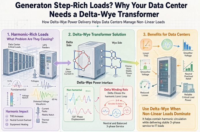
A delta-wye transformer does not clean up a data center’s harmonics. Its delta winding absorbs the third, ninth and fifteenth by circulating them as heat in its own copper, and the fifth and seventh, which do most of the heating, pass straight through untouched. What delta-wye actually buys you is a grounded four-wire secondary and a zero-sequence block between your ground faults and the utility.
That distinction matters because it changes what you specify. If you buy delta-wye expecting harmonic relief, you will still need the K-rating, and you will still be surprised by a transformer running hotter than its nameplate suggests. If you buy it for the grounding and the neutral, and separately buy the harmonic solution from the rectifier vendor, both problems get solved by the party best placed to solve them.
This article separates the two. It walks through what the delta physically does with a harmonic current, which harmonic orders it stops and which it ignores, how much heat the trapped current actually makes, where the neutral current comes from and when it exceeds the phase current, how the K-factor is really calculated, and why the choice of rectifier inside a server moves the transformer frame size more than the vector group does. Every number is worked on a 1,000 kVA, 480 delta to 208Y/120 unit at 5.75 percent impedance, so you can substitute your own and follow the arithmetic.
The short answer
Three sentences, in the order that matters.
First, the delta winding of a delta-wye transformer gives zero-sequence current a closed path. Third, ninth and fifteenth harmonic currents are zero sequence when the load is balanced, so they circulate in the delta and never reach the primary. That is real, and it is worth having.
Second, that circulation is not free and not large. On the 1,000 kVA unit in this article, the third harmonic current trapped in the delta comes to about 1.6 percent of the winding’s copper loss. It is a rounding error in thermal terms, which is why the transformer that “handles harmonics” is not actually being protected by its own connection.
Third, the harmonics that do the damage are the fifth and seventh from three-phase rectifiers, and those are positive and negative sequence. The delta has no path for them. At 65 percent fifth harmonic they produce more than ten times the rated eddy loss in the winding, and the vector group does nothing about it.
So the honest version of “data centers need delta-wye” is this. They need it because the load is four-wire, because the ground reference has to come from somewhere, and because a data center’s ground faults must not appear as residual current on the utility’s ground relay. The harmonic benefit is a side effect that applies mostly to the small single-phase part of the load.
What the delta actually does with a harmonic current
Start with the winding, not the marketing.
A delta winding is a closed loop with no external connection to neutral. Any current whose three phase components are equal in magnitude and in phase has nowhere to go except around that loop. That is the definition of a zero-sequence current, and in a balanced three-phase system the triplen harmonics, orders 3, 9, 15 and so on, are exactly that.
When a wye-connected load draws third harmonic current, the three phase currents are in phase with each other. They cannot sum to zero in a neutral the way fundamental currents do, because they are not 120 degrees apart. They add. On the primary side, the delta provides the return path they need, so instead of being forced through the transformer’s magnetic circuit and out to the utility, they circulate inside the delta.
The magnetic half of the argument
There is a second effect that is easier to miss. Circulating third harmonic current in the delta produces a magnetizing ampere-turn pattern that cancels the third harmonic flux the load was trying to establish. The core flux stays closer to sinusoidal. That is the real reason a delta-wye transformer runs cooler on a triplen-rich load than a wye-wye without a tertiary, and it is a magnetic argument, not a filtering one.
Here is the part that gets lost. The current did not disappear and it was not filtered. It was redirected into a winding that has resistance. The energy it carries becomes heat in that winding, at a loss proportional to the square of the current. The delta is not a filter. It is a shunt.
That distinction is worth holding onto, because “the delta traps the harmonics” is repeated so often that people stop asking where they went.
Which harmonics the delta stops, and which it waves through
The order matters, and so does the sequence.
| Order | Sequence | Does the delta block it | Share of eddy loss at typical amplitude |
|---|---|---|---|
| 3rd | zero | Yes, circulates | Moderate, but current is limited to the single-phase share of load |
| 5th | negative | No | Dominant on six-pulse rectifier load |
| 7th | positive | No | Second largest on six-pulse load |
| 9th | zero | Yes, circulates | Small |
| 11th | negative | No | Small on six-pulse, dominant on twelve-pulse |
| 13th | positive | No | Small on six-pulse, second on twelve-pulse |
| 15th | zero | Yes, circulates | Very small |
Three-phase rectifiers, which is what a server power supply and a UPS actually are, produce characteristic harmonics at 6k plus or minus 1: the 5th, 7th, 11th, 13th, 17th, 19th. They produce no triplen at all, because the three-phase bridge is balanced and has no neutral connection. This is the point that the standard “data centers need delta-wye for harmonics” argument skips over.
A six-pulse rectifier with no DC link choke produces a current spectrum that looks roughly like this, in per unit of the fundamental:
| Order | Amplitude | Eddy loss contribution |
|---|---|---|
| 5th | 0.65 | 10.56 |
| 7th | 0.41 | 8.24 |
| 11th | 0.085 | 0.87 |
| 13th | 0.077 | 0.99 |
| 17th | 0.044 | 0.56 |
| 19th and up | smaller | about 1.3 |
| Total | THD 78 percent | 22.5 |
Every entry in that right-hand column is the amplitude squared times the order squared, which is the multiplier on eddy current loss in the winding. The fifth harmonic alone contributes 10.56, and the delta has no path for it. The triplen contribution is zero, because there is no triplen.
Run the same arithmetic on the single-phase part of the load, which is where triplen actually comes from:
| Order | Amplitude | Eddy loss contribution |
|---|---|---|
| 3rd | 0.85 | 6.50 |
| 5th | 0.60 | 9.00 |
| 7th | 0.40 | 7.84 |
| 9th | 0.20 | 3.24 |
| 11th | 0.10 | 1.21 |
| Total | THD 114 percent | 27.8 |
Now the triplen share is 9.74 out of 27.8, or 35 percent. That is the only load category where the delta earns its reputation, and it is the category that has been shrinking for twenty years.
Trapping is not deleting, and the number is smaller than you expect
Where the current goes, in amps
Take the 1,000 kVA unit. At 208 V the secondary line current is 2,775.7 A. At 480 V the primary line current is 1,202.8 A, and because the primary is delta connected, each winding carries that divided by the square root of three, which is 694.4 A.
Now put 15 percent of the load on 120 V single-phase supplies with an 85 percent third harmonic. That is 416 A of fundamental per leg, 354 A of third harmonic per leg, and a neutral current of three times 354, which is 1,062 A, or 38 percent of the phase current.
Those 354 A reach the delta. Referred through the 4 to 1 per-phase turns ratio of a 480 to 120 V winding, they appear as 88.5 A circulating in each delta winding, against a winding rating of 694.4 A. That is 12.7 percent of rated current, which squared is 1.6 percent of that winding’s copper loss.
One point six percent. That is the entire thermal benefit of the delta on this load.
Set that against the fifth harmonic on the same transformer. A six-pulse load at 65 percent fifth harmonic puts 0.65 per unit of current into a winding, and the eddy loss multiplier is 0.65 squared times 25, which is 10.56, or 1,056 percent of rated eddy loss. At an eddy fraction of 15 percent of load loss, the load loss multiplier comes out at 4.89.
| Harmonic | Per unit current | Eddy loss multiplier | Copper loss increase |
|---|---|---|---|
| 3rd, from a 15 percent single-phase load | 0.128 | 0.146 | 1.6 percent |
| 5th, six-pulse, no choke | 0.650 | 10.56 | 42.2 percent |
| 7th, six-pulse, no choke | 0.410 | 8.24 | 16.8 percent |
| 11th, six-pulse, no choke | 0.085 | 0.874 | 0.7 percent |
The harmonic the delta blocks costs 1.6 percent of one winding’s copper loss. The harmonic it passes costs 42 percent of the whole transformer’s copper loss plus a tenfold increase in eddy loss. The ratio between them is about 72 to 1 in eddy terms.
That is the whole argument in one comparison. The connection is doing something real, and the thing it is doing is not the thing that is overheating your transformer.
The 33.3 percent line, and why it decides your neutral
Neutral current from triplen harmonics is not a square root sum. It is arithmetic addition, and that single fact explains the whole neutral sizing conversation.
When the load is balanced and the third harmonic content is the same on all three phases, the three third harmonic currents are in phase with each other. They do not cancel in the neutral. They add. If each phase carries a third harmonic of I3, the neutral carries three times I3.
Set that equal to the phase fundamental current. The neutral current equals the phase current when 3 times I3 equals I1, which is when I3 is 33.3 percent of the fundamental.
| Third harmonic, percent of fundamental | Neutral current, percent of phase |
|---|---|
| 20 | 60 |
| 30 | 90 |
| 33.3 | 100 |
| 50 | 150 |
| 66.7 | 200 |
| 85 | 255 |
Two useful lines fall out of that table. A neutral sized at 200 percent of the phase is exactly adequate up to 66.7 percent third harmonic, and not one point beyond. A neutral sized at 173 percent, the square root of three, is adequate up to 57.7 percent.
When the neutral becomes the largest conductor in the building
On the 1,000 kVA unit, a 33.3 percent third harmonic means 2,776 A in the neutral against 2,776 A in the phase. At 85 percent it means 7,078 A in the neutral against 2,776 A in the phase. The neutral becomes the largest conductor in the building.
Why 200 percent neutral is a 1998 answer
The 200 percent neutral exists because of a real failure mode. A 1990s server power supply with no power factor correction drew a current waveform that was nearly a series of pulses, with a third harmonic around 85 percent of the fundamental. Thirty percent of a data center’s load on those supplies was enough to make the neutral the hottest conductor in the room.
That load is largely gone. An 80 PLUS Platinum or Titanium supply has active power factor correction and a total harmonic distortion around 5 percent, with the third harmonic at 3 to 4 percent. Compute the neutral current against a realistic mixed load and the picture changes completely.
Take 15 percent of the 1,000 kVA unit on 120 V single-phase supplies, which is a generous allowance for management ports, cameras, door controllers and convenience outlets.
| Supply type | Third harmonic | Neutral current | Share of phase |
|---|---|---|---|
| No PFC, 1990s | 85 percent | 1,062 A | 38 percent |
| Passive PFC | 30 percent | 375 A | 13.5 percent |
| Active PFC | 4 percent | 50 A | 1.8 percent |
At 38 percent of phase current, a 100 percent neutral is already oversized. The 200 percent neutral is doing nothing except adding copper to the transformer and to every feeder downstream.
There is a cleaner way to state the condition. The neutral only exceeds the phase current when the single-phase share of the load, as a fraction of total kVA, exceeds one divided by three times the third harmonic fraction.
| Third harmonic | Single-phase share needed for the neutral to beat the phase |
|---|---|
| 85 percent | 39 percent |
| 60 percent | 56 percent |
| 30 percent | 111 percent, which cannot happen |
| 4 percent | 833 percent, which cannot happen |
So the specification question is not “is this a data center.” It is “what fraction of this load is single phase, and what supplies are on it.” A colocation hall full of three-phase 208 V racks feeding rectifiers has no triplen problem at all, because there is no neutral current to speak of. A hall full of 120 V outlets and legacy gear might.
None of that changes the case for a full-size neutral, which is cheap insurance and a code question rather than a thermal one. It changes the case for 200 percent, which should be an answer to a measured spectrum rather than a default.
K-factor is a multiplier on eddy loss, not a certificate
The K-factor gets treated as a label you pick off a list. It is a number you calculate, and the calculation is short enough to do on a napkin.
Where the loss split comes from
Start with where the loss goes. At rated load with a sinusoidal current, load loss splits into two parts: the resistance loss in the copper, I squared R, and the eddy and stray loss induced in the windings and structure by the leakage field. Call the eddy share f. For a dry-type distribution unit, f is of order 15 percent. For a liquid-filled unit it runs closer to 6 percent, because the winding geometry and the transposition are different.
Resistance loss scales with the square of the current, whatever the frequency. Eddy loss scales with the square of the current and with the square of the frequency, because the induced voltage rises with frequency and the impedance to it rises with frequency, so the loss rises with frequency squared.
That gives the K-factor its physical meaning. It is the weighted average of order squared, weighted by current squared:
K equals the sum of Ih squared times h squared, divided by the sum of Ih squared, with the fundamental included in both sums.
The fundamental is what makes the number come out in the range people recognize. Without it, a pure fifth harmonic at 65 percent would give a K of 25, which nobody quotes. With it, the denominator is 1 plus the squared distortion and the answer lands where the industry expects.
| Spectrum | THD | Sum Ih squared | Sum Ih squared h squared | K |
|---|---|---|---|---|
| Six-pulse, no reactor | 78 percent | 0.608 | 22.51 | 14.6 |
| Six-pulse, 4 percent DC choke | 38 percent | 0.146 | 5.58 | 5.7 |
| Twelve-pulse | 12.7 percent | 0.016 | 3.53 | 4.5 |
| Active front end, 4 percent THD | 3.6 percent | 0.001 | 0.05 | 1.05 |
| Single-phase supply, no PFC | 114 percent | 1.292 | 27.79 | 12.6 |
Every one of those is a real design point. The standard ratings are K-4, K-9, K-13 and K-20, so the first row needs K-20, the second row is comfortable at K-9, and the fourth row is fine on any standard unit.
From K to a frame size
Now the part that turns K into a purchasing decision. The load loss at the harmonic spectrum, relative to rated load loss, is:
Sum Ih squared, multiplied by the bracket one minus f plus f times K.
For the six-pulse, no-reactor row with f at 15 percent, that is 1.608 times the bracket 0.85 plus 2.19, which is 1.608 times 3.04, or 4.89. The transformer is producing nearly five times its rated load loss at full fundamental current.
Usable capacity goes as the inverse square root of that, on the assumption that temperature rise tracks total loss and the cooling is roughly linear:
| Spectrum | Loss multiplier, f = 0.15 | Usable share of nameplate | Frame needed for 1,000 kVA of load |
|---|---|---|---|
| Six-pulse, no reactor | 4.89 | 45 percent | 2,500 kVA |
| Six-pulse, 4 percent DC choke | 1.96 | 71 percent | 1,500 kVA |
| Twelve-pulse | 1.54 | 80 percent | 1,500 kVA |
| Active front end | 1.01 | 100 percent | 1,000 kVA |
Read the last column and then read the first. The same 1,000 kVA of load needs either a 2,500 kVA transformer or a 1,000 kVA transformer, depending entirely on what the rectifiers do.
Two honest caveats. The 15 percent eddy share is a design assumption, and a K-rated unit is built with a lower one, which is precisely what the K-rating pays for. And the inverse square root is an approximation, because cooling is not perfectly linear and the hot spot does not track average loss exactly. The direction and the order of magnitude are solid. The third digit is not.
That is why the right specification is not “K-13” but “the unit shall remain within its rated temperature rise when serving the spectrum tabulated in Appendix A.” A K label is a promise about a spectrum someone else assumed. Your appendix is a promise about your spectrum.
The part inside the server that decides your transformer size
Here is the practical consequence, and it is the single most useful number in this article.
Compare a six-pulse rectifier with no DC link choke against the same rectifier with a 4 percent choke. The choke is a small iron-cored inductor on the DC side of the bridge, and on a server power supply it is a minor bill of materials item.
| No choke | 4 percent choke | |
|---|---|---|
| Fifth harmonic | 65 percent | 35 percent |
| Seventh harmonic | 41 percent | 12 percent |
| THD | 78 percent | 38 percent |
| K-factor | 14.6 | 5.7 |
| Loss multiplier at full load | 4.89 | 1.96 |
| Transformer frame for 1,000 kVA of load | 2,500 kVA | 1,500 kVA |
The choke does not remove the harmonics. It halves the fifth and cuts the seventh by two thirds, and that is enough to move the transformer requirement by 1,000 kVA of frame.
This is the argument to have with the IT side, and it usually gets settled in the wrong room. The electrical engineer specifies a K-20 transformer at a premium. The IT buyer chooses a power supply on efficiency certification and price, and reads nothing into whether it has a DC choke, because the certification does not require one. Nobody connects the two decisions, and the cost lands on the electrical budget.
For a 1,000 kVA hall, the difference between a 2,500 kVA frame and a 1,500 kVA frame is not a rounding error in either first cost or floor space. It is also not something you can fix after the fact, because the transformer arrives before the servers do.
One more layer to this. If you do not know the spectrum, which is the normal case on a new build, the specification that works is a loss limit rather than a K label. State the load loss the unit must not exceed at the specified spectrum, and require the vendor to calculate it with the same formula in this section. A vendor who can do that calculation will also tell you when your spectrum assumption is wrong, and that conversation is worth more than the label.
The UPS decides the spectrum, and the server just rides on it
There is one more layer between the utility and the servers, and it is usually the largest harmonic source in the building.
A double-conversion UPS rectifies the incoming AC, charges a DC bus and reinverts it. That rectifier is a three-phase bridge, which means its input current spectrum is the same family as a drive’s, and its magnitude is set by the UPS design rather than by the IT load. A six-pulse UPS rectifier without an input filter runs at 30 percent THD or worse. A twelve-pulse unit halves that. A modern unit with an active rectifier runs at 3 to 5 percent.
The consequence is that the transformer’s harmonic load is the UPS input, not the servers. Two halls with identical IT load can have completely different spectra because they bought different UPS.
Now add the part that gets missed in the design case. A UPS rectifier is sized to carry the IT load plus battery recharge, and recharge happens after every outage. That is when the input current peaks, and it is when the transformer sees its worst harmonic hour.
| Operating state | UPS input, kVA | Percent of 1,000 kVA transformer | Harmonic current |
|---|---|---|---|
| Normal, 600 kW at 0.95 power factor, 96 percent efficient | 658 | 66 | Nominal spectrum |
| Full load at 0.95 power factor plus battery recharge | 1,100 | 110 | Spectrum at 110 percent current |
At the recharge condition the transformer is above its nameplate kVA with a harmonic spectrum on top, and the eddy loss multiplier applies to the whole of it. If the design case was evaluated at 66 percent load with a nominal spectrum, the number that matters was never computed.
Three practical consequences.
Evaluate at the recharge condition. The harmonic study should carry a row for the two hours after a full discharge, with the rectifier at its maximum input current. That is the thermal design case for the transformer, and it is the one that is almost always missing from the submittal.
Ask whether the UPS rectifier is active or passive. This single question moves the transformer frame size more than any other line in the specification, and it belongs in the same conversation as the UPS efficiency rating rather than in a separate electrical package.
Walk-in matters more than it looks. A rectifier that ramps its input current over 30 seconds after a transfer puts less stress on the transformer and less voltage distortion on the bus than one that steps to full load. It costs a software setting, and it is worth asking for.
The transformer moves you to a different IEEE 519 row
IEEE 519 is the standard a utility will point at when it says your harmonics are a problem. It is often summarized as “5 percent THD,” which is wrong in two ways. It limits voltage distortion at the point of common coupling, and it limits current distortion as total demand distortion, TDD, on a sliding scale that depends on the ratio of available short circuit current to load current.
The scale runs from strict to loose as the source gets stiffer:
| Short circuit ratio Isc divided by IL | TDD limit | Limit for the 5th harmonic |
|---|---|---|
| Less than 20 | 5 percent | 4.0 percent |
| 20 to 50 | 8 percent | 7.0 percent |
| 50 to 100 | 12 percent | 10.0 percent |
| 100 to 1,000 | 15 percent | 12.0 percent |
| Above 1,000 | 20 percent | 15.0 percent |
The dedicated transformer makes the source look weak
Now the counterintuitive part. A dedicated transformer with 5.75 percent impedance is a weak source from the harmonic point of view, even when the utility behind it is strong, because the transformer’s own impedance limits the fault current.
On the 1,000 kVA unit, the 480 V bus sees a fault current of 20,918 A against a full load current of 1,202.8 A. The ratio is 17.4, which puts you in the strictest row, the one with a 5 percent TDD limit.
| Spectrum | TDD | Against the 5 percent limit | Against the 20 percent limit |
|---|---|---|---|
| Six-pulse, no reactor | 78 percent | 15.6 times | 3.9 times |
| Six-pulse, 4 percent choke | 38 percent | 7.7 times | 1.9 times |
| Twelve-pulse | 12.7 percent | 2.5 times | 0.6 times |
| Active front end | 3.6 percent | 0.7 times | 0.2 times |
Only the active front end passes at the 480 V bus. Now move the point of common coupling to the 13.8 kV service, which is where the utility actually measures when you own the transformer. A 500 MVA source at 13.8 kV gives a fault current of 20,918 A there as well, but the load current is only 41.8 A, so the ratio is 500 and the limit becomes 15 percent.
Twelve-pulse now passes. Nothing else changes about the load. The harmonic current is the same, the TDD percentage is the same, and the row of the table is different because the impedance between you and the source is different.
That is what the transformer does for harmonic compliance. It does not filter. It changes which row you are measured against, by changing the short circuit ratio at the point of common coupling. Whether that helps or hurts depends on where your utility draws the line, and it is worth asking before you sign the interconnect agreement.
TDD is not THD, and part load flatters you
The two numbers are computed with different denominators, and the difference is large enough to end arguments.
THD divides the harmonic content by the fundamental current at the moment of measurement. TDD divides it by the maximum demand current over the measurement interval. Since the maximum demand is at least as large as the present fundamental, TDD is always the smaller of the two, and the gap widens as the load falls.
A drive with 78 percent THD at full load reads about 47 percent TDD when the hall is running at 60 percent load, on the simplifying assumption that the harmonic currents scale down with the fundamental. They do not scale perfectly, because a lightly loaded rectifier produces harmonics that are a larger fraction of its own fundamental, so the real number sits between 47 and 78.
The practical takeaway cuts both ways. A vendor quoting a compliant TDD measured at 30 percent load has told you very little. A tenant complaining about a 78 percent THD reading on a meter at 2 a.m. has also told you very little. Ask for both numbers at the same load, and ask what the maximum demand was set to.
The generator is where harmonic voltage actually bites
Everything up to here has been about current. What the IT load experiences is voltage, and voltage distortion depends on the source impedance rather than on the vector group.
Harmonic current flowing into a source produces a voltage drop that is larger than the same current at fundamental, because leakage reactance scales with frequency. The fifth harmonic sees five times the reactance, the seventh sees seven times. On the 1,000 kVA unit at 5.75 percent, the fifth harmonic sees 28.75 percent, not 5.75.
That matters most on generator. A data center on utility power has a source impedance dominated by a large network, and the transformer is most of what stands between the load and a very stiff system. On generator, the alternator’s subtransient reactance is added in series, and it is usually larger than the transformer’s.
| Source configuration | Impedance at fundamental, on 1,000 kVA | Impedance at the 5th |
|---|---|---|
| Utility, 500 MVA, plus transformer | 5.95 percent | 29.8 percent |
| Generator, 2,500 kVA at 15 percent subtransient, plus transformer | 11.75 percent | 58.8 percent |
Roughly double, which means roughly double the voltage distortion from the same harmonic current.
Take the 1998 mix from earlier, 80 percent six-pulse rectifiers and 20 percent single-phase supplies, and run it at 40 percent of the transformer rating. The fifth harmonic current is 0.65 times 0.8 times 0.4, which is 0.208 per unit. Multiplied by the impedances above:
| Load level | Fifth harmonic voltage, utility | Fifth harmonic voltage, generator |
|---|---|---|
| 30 percent | 4.6 percent | 9.2 percent |
| 50 percent | 7.7 percent | 15.3 percent |
| 70 percent | 10.8 percent | 21.4 percent |
These are upper bounds, because the harmonic current itself falls as the source impedance rises, and field measurements typically land 30 to 40 percent below them. Even so, the shape of the table is the whole story. A hall that measures 4.6 percent voltage distortion on utility power measures 9.2 percent within seconds of a transfer to generator, with nothing changed except the source.
That is why drives trip on generator and not on utility, why the transfer test is the day the harmonic problem is discovered, and why it gets logged as a UPS event rather than a power quality event. The current distortion did not change. The impedance it flows through did.
Here is the part that makes this a specification problem rather than a physics lesson. The IEEE 519 current limit at the point of common coupling does not change when you transfer to generator, because the short circuit ratio at the 480 V bus only falls from 17.4 to about 8.5, and both sit in the same row of the table. So a hall can be fully compliant on current and still put 8 percent voltage distortion on the servers.
The number the IT load cares about is the voltage distortion at the PDU input, and the usual design target is 5 percent, which comes from IEEE 1100 and is repeated in most data center design guides. Compliance with the current table does not deliver that. Only the source impedance and the harmonic current together do.
Three things follow, and none of them is a vector group.
Ask for the generator’s subtransient reactance, not just its kVA. A 2,500 kVA machine at 10 percent presents 4 percent on the transformer base and behaves very differently from one at 18 percent. The difference is worth more than a K-rating.
Design for the transfer, not for the utility. The harmonic study should be run in both source configurations, and the voltage distortion at the PDU should be reported for both. A study that only covers the utility case has answered the easy half of the question.
Fix the current at the source. A choke, a twelve-pulse arrangement or an active front end reduces the harmonic current that flows into the high impedance source. A delta winding cannot, because the fifth harmonic was never going to circulate in it.
The meter that reads zero
Third harmonic voltage behaves differently from third harmonic current, and this is where a commissioning test can go wrong in a way that costs a year.
Line-to-neutral voltage contains the triplen. Line-to-line voltage does not, because the difference between two phases cancels any component that is identical in both. So a meter connected phase to phase reports a cleaner system than the one the loads actually see.
| Line-to-neutral THD | Of which third harmonic | Line-to-line reading |
|---|---|---|
| 5.0 percent | 3.0 percent | 4.0 percent |
| 8.0 percent | 5.0 percent | 6.2 percent |
| 5.0 percent | 5.0 percent | 0.0 percent |
| 6.0 percent | 2.0 percent | 5.7 percent |
The third row is the one to remember. If all of the distortion is third harmonic, the line-to-line meter reads zero and the phase-to-neutral waveform is visibly flat-topped.
On a delta-wye transformer this matters more than on any other connection, because the delta passes the triplen current through to the wye side while blocking it from the primary. The secondary phase voltage carries the distortion, the secondary line voltage hides it, and the primary sees nothing. Three meters on the same transformer, three different answers, and the connection explains all three.
The practical instruction is short. On a delta-wye unit feeding single-phase electronic load, put the power quality meter in phase-to-neutral mode and look at the waveform, not just the RMS. A flat-topped sine at 5 percent THD will do more damage to a power supply’s input capacitors over ten years than a clean sine at 8 percent.
The three real reasons data centers specify delta-wye
Strip out the harmonic argument and three reasons remain. They are all about the low-voltage system, not the high-voltage one.
You need a four-wire secondary. A rack PDU is a 208Y/120 device or a 415Y/240 device. Both need a neutral and both need a line-to-neutral voltage that is stable. A delta secondary gives you three wires and a line-to-line voltage only, which is fine for a motor and useless for a server. If any part of the load is line-to-neutral, the secondary has to be wye, and the primary has to be delta if you want the zero-sequence behaviour described earlier.
You need the ground reference to be yours. A solidly grounded wye secondary is a zero-sequence source for the low-voltage system, with a low zero-sequence impedance. That is what makes a 208 V ground fault trip a breaker quickly and selectively instead of sitting there as an arcing fault. The delta primary is what stops that same fault from appearing as residual current on the utility’s ground relay. The two zero-sequence networks are isolated from each other, which means the utility’s ground element cannot see your ground faults, and yours cannot see theirs. That isolation is the thing that makes coordination across the transformer possible at all.
It also means a high-voltage ground element cannot back up a low-voltage ground fault, because there is no residual current on the high side to operate it. Backup has to come from a high-side phase element, a low-side element, or the transformer neutral. This is a coordination fact that surprises people, and it comes directly from the delta.
You may want the thirty degrees. A delta-wye unit displaces the secondary by 30 degrees, and that displacement is what lets a pair of transformers create a twelve-pulse effect, or what stops two units from being paralleled. Which of those two outcomes you get depends on the clock number, and the clock number belongs on the drawing.
What the delta costs you on the low side
The same low zero-sequence impedance that makes ground faults clear quickly also makes them large.
On the 1,000 kVA unit, a three-phase fault at the 208 V terminals is 48,273 A. A single line-to-neutral fault is not much smaller, because the wye winding with a delta primary presents a low zero-sequence impedance and the ground fault current approaches the three-phase value. That is why 208 V switchboards in data centers are commonly specified at 65 kA and sometimes at 100 kA, while the transformer that feeds them is only 1,000 kVA.
Why the low side sees 48,000 amps
Two consequences follow.
First, the interrupting rating of the low-voltage equipment is set by the transformer, not by the load. A 1,000 kVA transformer at 5.75 percent impedance will produce about 48 kA at 208 V whether the hall is full or empty. Choose the switchboard on that number, and check the series rating of every breaker downstream of it.
Second, the choice of grounding changes the failure mode more than the choice of vector group does. An ungrounded delta keeps running after a single ground fault, which sounds attractive until you work out the voltage. With one leg solidly grounded, the other two rise to the full line voltage of 480 V, which is 1.73 times the normal 277 V to ground. Every cable, every surge arrestor and every piece of insulation on those two legs now sees a voltage it was not rated for, and the fault is silent until the second one arrives.
For a data center, tripping on the first ground fault is the right answer. That is a grounded wye, and it is another reason the connection is not really a harmonic decision.
The neutral is a current-carrying conductor, and that costs a size
NEC 310.15(E)(3) says that on a four-wire, three-phase wye circuit where the major portion of the load consists of nonlinear loads, the neutral is considered a current-carrying conductor for ampacity adjustment. The reason given in the informational note is exactly the arithmetic in this article: harmonic currents are present in the neutral.
The consequence is not intuitive. A feeder with three current-carrying conductors gets no adjustment. Add the neutral as a fourth and Table 310.15(C)(1) applies an 80 percent factor to the whole feeder, not just to the neutral.
| Feeder | Three counted conductors | Four counted conductors |
|---|---|---|
| 2 sets of 3/0 copper at 75 C | 450 A | 360 A |
| 2 sets of 250 kcmil copper at 75 C | 510 A | 408 A |
A 400 A feeder built as two sets of 3/0 passes at 450 A and fails at 360 A once the neutral counts. The fix is one size up, two sets of 250 kcmil at 408 A, which is 11 percent more copper on every foot of that run.
Scale it to the transformer secondary and the number gets bigger. The 208 V secondary of the 1,000 kVA unit needs 2,776 A, which is eight sets of 500 kcmil at 3,040 A. Count the neutral and the same eight sets derate to 2,432 A, so you need ten sets, which is 25 percent more copper in that ductbank.
Two things are worth saying about that rule. The Code does not define “major portion,” and the common reading is more than half. And the rule is about ampacity adjustment, not about conductor sizing for the neutral current itself, which is a separate calculation. But the practical effect is that the harmonic content of your load, which you cannot control after the tenant moves in, sets the copper content of your feeders, which you buy before they do.
There is a legitimate design response. If the hall is all three-phase 208 V racks with active power factor correction, the neutral current is a few percent of phase current, the load is not mostly nonlinear in the sense that matters, and the neutral does not need to count. That is a defensible position, and it needs to be written down with a measured spectrum behind it rather than assumed.
What this means if you are retrofitting
Most of this article is written for a new build, where the transformer and the rectifiers are chosen together. Retrofits are harder, because one of the two is already bolted to the floor.
If the transformer exists and the load is changing, the vector group is fixed. Delta-wye is what is there, or it is not, and nothing in the harmonic discussion will change it. What is still open is everything downstream.
The sequence that works is to measure the existing spectrum, calculate the K-factor, calculate the loss multiplier at the new load, and compare the result against the transformer’s actual temperature rise rather than its nameplate. A unit running 15 kelvin below its rated rise has margin that a nameplate calculation does not show, and a unit running at its limit has none.
Three retrofit moves, in order of cost.
Fix the rectifiers first. A DC link choke on a drive, an input reactor on a UPS, or a replacement power supply with active power factor correction. These reduce the harmonic current at the source, which is the only place it can be reduced without adding equipment.
Then filter. An active harmonic filter at the 480 V bus cancels the fifth and seventh in real time and does nothing for a ground fault. It is the right answer when the transformer cannot be replaced and the spectrum cannot be changed.
Then derate. If nothing else changes, the honest answer is to cap the load at the usable capacity the loss multiplier allows. A 1,000 kVA transformer serving a spectrum with a multiplier of 1.96 is an 800 kVA transformer with a 1,000 kVA label, and operating it as such is not a compromise. It is what the arithmetic already says.
What does not work is changing the vector group. A replacement transformer with the same kVA and a different connection will have the same thermal problem, because the fifth harmonic does not care which way the windings are connected.
How to get the spectrum before you buy
Every number in this article depends on a spectrum, and most projects do not have one at the time the transformer is ordered. There is a way to get close enough, and it takes less effort than the arguments it prevents.
Measure at maximum demand, not at two in the morning
A power quality logger recording for seven days will produce a THD figure for every minute, and the average of those figures is meaningless. What matters is the reading at maximum demand, because that is when the harmonic currents are largest in absolute terms and when the transformer is hottest.
Record the individual orders from the second to the twenty-fifth, not just the total. A THD of 12 percent made of fifth and seventh is a different problem from a THD of 12 percent made of third and ninth, and only the order breakdown tells you whether the delta is helping.
Ask the power supply vendor for two spectra
A rectifier’s spectrum changes with load. At 50 percent load a six-pulse supply often produces a higher THD percentage than at 100 percent, because the DC link current becomes discontinuous and the current waveform becomes peakier. So ask for the spectrum at half load and at full load, and design for whichever gives the higher K-factor.
If the vendor cannot supply it, that is information too. A supplier who has never measured the input current spectrum of their own product is unlikely to have built it to a harmonic target.
Know what a modern load actually looks like
The three load categories in a data center have very different spectra, and the mix decides everything.
| Load category | Typical spectrum | Triplen content |
|---|---|---|
| UPS with active front end | 3 to 5 percent THD, mostly 5th and 7th | None |
| Server supplies with active PFC | 3 to 8 percent THD, 3rd at 3 to 4 percent | Small |
| Server supplies with no PFC, older gear | 80 to 120 percent THD, 3rd at 80 to 90 percent | Large |
| Single-phase LED drivers and small supplies | 10 to 20 percent THD, 3rd dominant | Large |
The bottom two rows are the ones that create neutral current, and they are also the two rows that are smallest in a modern hall. That is the whole reason the 200 percent neutral conversation has changed while the specification language has not.
Read the crest factor
One more number is worth collecting because it costs nothing. The crest factor of the phase current, which is peak divided by RMS, tells you how peaky the waveform is. A sinusoidal current has a crest factor of 1.414. A six-pulse rectifier without a choke runs near 2.0, and a single-phase supply without power factor correction can exceed 2.5.
A high crest factor is what makes a neutral and a breaker heat up in ways the RMS reading does not predict, and it is the reason some breakers with thermal magnetic trips nuisance trip on harmonic load at currents well below their rating.
When delta-wye is the wrong answer
Four cases, and the first one is the most common.
When you are buying it as a harmonic solution. If the load is six-pulse rectifiers and the plan is “delta-wye will handle the harmonics,” the plan does not work. The fifth and seventh have no zero-sequence path, so they pass. You still need the K-rating, the choke, the twelve-pulse arrangement or the active filter. Buying delta-wye and skipping the rest is the most expensive way to be wrong, because the transformer arrives and the problem does not.
When the load is three-wire and always will be. A hall of 480 V or 415 V three-phase IT load with no line-to-neutral requirement does not need a wye secondary for the load. It still needs a ground reference and it still needs the zero-sequence block, so delta-wye often remains the answer, but the reason has changed and the neutral can be sized for the actual line-to-neutral load, which may be nearly zero.
When an active filter is cheaper than the frame. An active harmonic filter at the 480 V bus cancels the fifth and seventh in real time, which is exactly what the delta cannot do. Compare it against the alternative honestly: a 1,500 kVA frame instead of 2,500 kVA, plus the K-20 premium, plus the extra floor space and the extra cooling load from the higher losses. A filter has its own losses and its own failure modes, and it does nothing for a ground fault. But on a retrofit where the transformer is already installed, it is often the only option that does not involve a crane.
When two units have to be tied. That is the next section.
2N, two suppliers, and the tie that will not close
A 2N data center has two transformers that are supposed to be interchangeable. In practice they are bought at different times, sometimes from different suppliers, and the vector group is buried in a submittal.
Delta-wye comes in two clock numbers in North American practice. Dyn1 puts the low side 30 degrees lagging. Dyn11 puts it 30 degrees leading. Both are delta-wye. Both have 30 degrees of displacement. They are 60 degrees apart from each other.
Close a tie between them and the voltage difference across the open point is 1.0 per unit, because the vector difference at 60 degrees is twice the sine of 30 degrees. With two 5.75 percent units the circulating current is about 8.7 times rated, which is close to the bolted fault current of one unit. Both breakers trip, or neither does and the windings take the heat.
The design rule is short. Write the vector group and the clock number into the 2N specification, require the submittal to state it, and check it at commissioning with a phase angle measurement before the tie is ever closed. Two units from the same supplier with the same part number are fine. Two units from different suppliers with the same description are not.
A 1,000 kVA hall, worked end to end
Numbers are easier to trust when they are applied to a project. Take a 1,000 kVA hall, 480 delta to 208Y/120, 5.75 percent impedance, with this load:
| Load | kVA | Rectifier type |
|---|---|---|
| Three-phase IT load through UPS | 800 | Six-pulse with 4 percent DC chokes |
| Line-to-neutral load at 120 V | 150 | Active power factor correction |
| Mechanical and miscellaneous | 50 | Motor and resistive |
Step one, the spectrum
Weight the two harmonic sources by their share of the total, which is 0.80 and 0.15.
The squared distortion adds as 0.64 times 0.146 plus 0.0225 times 0.001, which is 0.0934, so the blended THD is 30.6 percent. The eddy weighting adds as 0.64 times 5.58, which is 3.57, and the K-factor is 4.57 divided by 1.093, or 4.18.
That lands on K-9, not K-20. The chokes in the UPS did that, not the vector group.
Step two, the frame
The loss multiplier is 1.093 times the bracket 0.85 plus 0.63, which is 1.62. Usable capacity is the inverse square root, 78.7 percent. Serving 1,000 kVA therefore needs 1,270 kVA of frame, and the next standard size is 1,500 kVA.
So the answer is a 1,500 kVA unit at K-9, and the reason it is not 1,000 kVA is 27 percent harmonic loss rather than 100 percent of it. Without the chokes the same load would need 2,500 kVA.
Step three, the neutral
The 150 kVA of line-to-neutral load is 416 A of fundamental per leg at 120 V. With active power factor correction at 4 percent third harmonic, the third harmonic per leg is 17 A, and the neutral carries three times that, which is 50 A.
Fifty amps against a phase current of 2,776 A is 1.8 percent. A 100 percent neutral is generous. The 200 percent neutral that the template specification calls for would add copper to the transformer and to every feeder for no thermal reason.
That conclusion is only safe because the spectrum is written down. If the tenant later installs legacy equipment, the assumption changes and the neutral becomes the constraint, which is why the specification should record the assumption rather than the conclusion.
Step four, the feeder
The 208 V secondary current is 2,776 A, which is eight sets of 500 kcmil copper at 380 A each, or 3,040 A in total.
If the neutral counts as a current-carrying conductor, those eight sets derate to 2,432 A and the design needs ten sets. That is 25 percent more copper, and it is a decision made by the harmonic content of the load rather than by the load itself. At this current level most projects use busway, which sidesteps the conductor adjustment question but not the neutral sizing question.
Step five, the compliance number
The blended TDD is 30.6 percent at the 480 V bus, against a limit of 5 percent because the short circuit ratio is 17.4. That is six times over.
This is the uncomfortable part of the worked example, and it is worth sitting with. Chokes move the frame from 2,500 kVA to 1,500 kVA and the K-factor from 14.6 to 4.2. They do not deliver IEEE 519 compliance at this bus. Only an active front end does, at 3.6 percent, and that is a UPS specification rather than a transformer specification.
So the honest summary of this hall is that the transformer is a 1,500 kVA K-9 delta-wye with a 100 percent neutral, and it is not the device that makes the hall compliant. The rectifier is. The transformer’s job is to deliver four-wire 208Y/120 with a ground reference, block zero sequence from the utility, and survive the spectrum it is given.
What to put on the purchase order
Six lines, in this order.
Vector group and clock number. Dyn1 or Dyn11, spelled out, with the ANSI equivalent if the project mixes conventions. Not “delta-wye.”
The spectrum. A table of harmonic orders and per unit amplitudes for the design load, with the source stated. If the design load is unknown, use the worst credible case and say so.
A loss limit, not a K label. The unit shall not exceed its rated temperature rise at the specified spectrum, and the vendor shall show the calculation using the eddy loss method. Then add the K rating as a floor, not as the requirement.
Neutral sizing. State the third harmonic content and the single-phase share, and derive the neutral from them. A 100 percent neutral is correct for an all-three-phase hall. A 200 percent neutral is correct when the single-phase share exceeds one divided by three times the third harmonic fraction. Both answers can be right on the same project in different parts of the building.
Zero-sequence impedance. Ask for it, in percent on the transformer base. It sets the low-voltage ground fault current, which sets the interrupting rating of every board downstream, and it is not on most data sheets.
The matching question. If the unit is going into a 2N pair, state the clock number of the existing unit and require a match. This costs nothing at the quotation stage and a great deal later.
The whole argument on one page
| Claim | What the arithmetic says |
|---|---|
| The delta blocks triplen harmonics | Yes. Third, ninth and fifteenth circulate in the delta and do not reach the primary |
| That is what saves the transformer | No. On a 1,000 kVA unit the trapped third harmonic is about 1.6 percent of one winding’s copper loss |
| The delta helps with rectifier harmonics | No. The fifth and seventh are not zero sequence and pass through |
| The fifth harmonic is a minor effect | No. At 65 percent it produces 1,056 percent of rated eddy loss and 42 percent more copper loss |
| Neutral current exceeds phase current on harmonic load | Only above 33.3 percent third harmonic, which needs a large single-phase share and legacy supplies |
| A 200 percent neutral is always safer | It is adequate to 66.7 percent third harmonic and unnecessary below about 19 percent single-phase share on modern supplies |
| K-factor is a label | It is the current-weighted average of order squared, including the fundamental |
| A K-13 unit handles six-pulse drives | Only with a choke. Without one the spectrum is K-14.6 and needs K-20 |
| The vector group affects IEEE 519 compliance | It changes the short circuit ratio at the point of common coupling, which changes the limit you are measured against |
| Delta-wye is specified for harmonics | It is specified for the four-wire secondary, the ground reference and the zero-sequence block. The harmonic benefit is small and specific |
The two mistakes worth guarding against are both cheap to prevent. Specifying delta-wye and treating the harmonic problem as solved, which leaves a transformer running at five times its rated load loss. And specifying a K-20 on a bare six-pulse load without asking why the frame has to be 2,500 kVA when 1,500 would do.
If the spectrum, the neutral sizing or the vector group is still open on your project, that is the conversation to have before the unit is released for manufacture. It starts here.
FAQ
Does a delta-wye transformer remove harmonics?
No. It gives zero-sequence harmonic current a closed path inside the delta, so third, ninth and fifteenth harmonics circulate there instead of reaching the primary. The fifth and seventh from three-phase rectifiers are not zero sequence and pass through. On a 1,000 kVA unit the trapped third harmonic is about 1.6 percent of one winding’s copper loss, while a 65 percent fifth harmonic raises eddy loss 10.6 times.
Which harmonic orders does a delta winding actually block?
The triplen orders: 3, 9, 15, 21 and so on, plus any other zero-sequence component. Everything else passes. That means the delta is useful against single-phase electronic load, which does produce triplens, and useless against the balanced three-phase rectifiers that make up most of a data center’s load, which produce none.
How much heat does the trapped third harmonic make?
Less than people assume. On a 1,000 kVA, 480 delta to 208Y/120 unit at 5.75 percent impedance, a 15 percent single-phase load with 85 percent third harmonic puts 354 A on each 120 V leg. Referred through the 4 to 1 winding ratio that is 88.5 A circulating in a 694 A delta winding, which is 12.7 percent of rating and 1.6 percent of that winding’s copper loss.
When does neutral current exceed phase current?
When the third harmonic exceeds 33.3 percent of the fundamental, because the three in-phase third harmonic currents add arithmetically in the neutral. At 33.3 percent the neutral equals the phase. At 85 percent, which is a 1990s supply with no power factor correction, the neutral is 2.55 times the phase current.
Do I need a 200 percent neutral?
Only if the third harmonic is above 66.7 percent of the fundamental, or if the single-phase share of the load exceeds one divided by three times the third harmonic fraction. With an 85 percent third harmonic that threshold is 39 percent of load. With active power factor correction at 4 percent third harmonic the threshold is 833 percent, which cannot happen.
What K-factor do I need for six-pulse drives?
Without a DC link choke the spectrum works out to K 14.6, which needs K-20. With a 4 percent choke it drops to K 5.7, which K-9 covers. Twelve-pulse works out to K 4.5, and an active front end at 4 percent THD is K 1.05. The K-factor is the current-weighted average of harmonic order squared, divided by the squared current, with the fundamental included in both sums.
Why does my line-to-line meter show no distortion?
Because third harmonic voltage is identical on all three phases, so it cancels in any line-to-line measurement. A system with 5 percent line-to-neutral distortion that is entirely third harmonic reads 0 percent line to line. Put the meter in phase-to-neutral mode and look at the waveform, or you will sign off a flat-topped supply as clean.
Will delta-wye help me meet IEEE 519?
Not by filtering. It changes the short circuit ratio at the point of common coupling, which changes which row of the current distortion table applies. A 1,000 kVA transformer at 5.75 percent gives a ratio of 17.4 at the 480 V bus, which is the 5 percent TDD row. Move the measurement to a 13.8 kV service fed from 500 MVA and the ratio becomes 500, which is the 15 percent row.
Can two delta-wye transformers be paralleled?
Only if the clock numbers match. Dyn1 and Dyn11 are both delta-wye and both have 30 degrees of displacement, but they are 60 degrees apart from each other. Closing a tie between them presents 1.0 per unit across the open point, which drives about 8.7 times rated current through two 5.75 percent units before either picks up load.
What is the one number worth putting in the specification?
The load loss the transformer must not exceed at your spectrum. A K label describes a spectrum someone else assumed. A loss limit with the spectrum attached forces the vendor to run the calculation and tells you when your assumption is wrong, which is worth more than the label and costs nothing at the quotation stage.