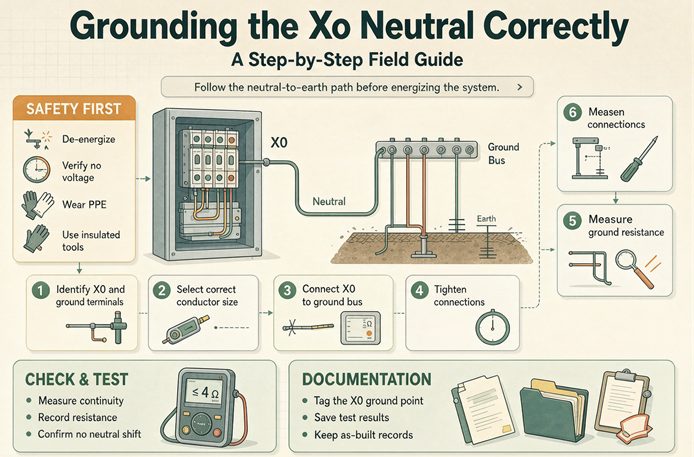
Grounding X0 is not one bolt. It is four decisions: is this a separately derived system, where is the single bonding point, which of four NEC tables sizes each conductor, and does the neutral go to ground solid or through a resistor. On one 2,500 kVA machine the fourth choice alone moves the ground fault from 50,350 A to 5 A.
If you landed here from one of our other transformer pages, this is the one about the bolt. The 480 V to 208Y/120 V page sizes the machine, picks the protection, and lists eight commissioning readings. The grounded wye page compares two grounding philosophies. Neither one tells you which of four code tables sizes the jumper in your hand, or why the same 2,500 kVA unit clears a 50,350 A fault in one plant and sits there with 5 A flowing in another. That is all we do here. No kVA tables, no vendor lists, no pricing.
The short answer, before the field steps
Here is the six-row comparison shape search engines like to pull, with the adjectives replaced by the decision that actually answers the question and a number you can check on site.
| If your question is | The decision that answers it | Number to check | What goes in the submittal |
|---|---|---|---|
| Is X0 even mine to ground | Decision one: is this an SDS | 3-pole ATS keeps one neutral, 4-pole makes a new source | Transfer switch pole count and the one-line |
| Where does the jumper land | Decision two: one point, source to first disconnect | 250.30(A)(1) through (A)(6), eight subparts | Bonding location, in writing |
| What size is the jumper | Decision three: Table 250.102(C)(1), not 250.122 | 3/0 AWG phase gives 4 AWG copper | Largest derived ungrounded conductor |
| Can I run 277 V lights | Decision four: the third condition in 250.36 | 480 to 1,000 V band, 2.08 times | Grounding method and an L-N load statement |
| How big is the ground fault | Decision four again | 50,350 A solid, 5 A with 55.4 ohm | Fault study at the secondary bus |
| Did the crew get it right | The meter, not the drawing | 0 to 1.5 V X0 to frame, 120 V L-N | Signed commissioning sheet |
Read the second column top to bottom. Not one row says “tighten the lug.” Every answer is a system classification, a location, a table, a load type, or a measured value. That is why a step list that starts at the terminal and ends at the torque wrench cannot answer the question in the title.
Seven steps, in the order a field crew does them
- Read the nameplate and the one-line. Confirm the wye secondary actually brings X0 out, and confirm whether the primary has any solid connection back to the supply neutral.
- Decide whether this is a separately derived system. If it is, it needs its own grounding point. If it is not, adding one creates a parallel neutral path.
- Pick the single bonding location, anywhere from the source to the first system disconnecting means, and write it on the one-line before anyone pulls wire.
- Size four conductors from four different rules: the system bonding jumper, the supply-side bonding jumper, the grounded conductor, and the grounding electrode conductor.
- Land the grounding electrode conductor on the building electrode system that already exists, at the same point where the system bonding jumper lands.
- Choose the grounding method, solid, low resistance, high resistance, or no intentional ground, and get the utility or the authority having jurisdiction to confirm it in writing.
- Energize and record: 208 V line to line, 120 V line to neutral, X0 to frame, phase rotation, and the ground fault loop impedance at the first panel.
Why step two decides everything else
Article 250 opens the separately derived system section with a sentence worth taping to the inside of the truck door. A grounding connection shall not be made to any grounded circuit conductor on the load side of the point of grounding of the separately derived system, except as the article permits. That one sentence is the reason a green screw in a downstream subpanel is a defect and not a spare ground.
People treat “ground it” as an instruction about a wire. The code treats it as an instruction about a location. Once the bonding point is chosen, every conductor downstream has one job and one name. The grounded conductor carries normal unbalanced load current. The equipment grounding conductor carries fault current only. Swap their jobs at a second bond and both of them carry both, all day, through your metal raceway, your building steel and your plumbing.
The three decisions that follow step two all inherit that choice. The jumper size depends on the derived conductors at the source, not on the breaker in the panel. The electrode conductor has to land where the jumper lands. And the fault current you design for depends on whether the neutral reaches ground through a bolt, a resistor, or nothing at all. Get step two wrong and the other three are being calculated for a system that does not exist.
What X0 is, and what it is not
X0 is a terminal mark. On a wye secondary it is the common point where the three winding ends meet, brought out so you can connect a neutral. The mark is a fact about the machine, printed on the nameplate and fixed at the factory. Whether that terminal gets bolted to an enclosure, run through a resistor, or left with no intentional ground reference is a fact about the system, decided by the engineer and the owner. Two different kinds of fact, one terminal.
That distinction clears up four conversations that go sideways on jobsites. First, X0 is not “the ground.” It is the grounded conductor’s origin, and it only becomes a grounding point after somebody installs a system bonding jumper. Second, a delta winding has no X0 at all, which is why a delta bus that needs a reference gets a grounding transformer instead. Third, on a three-can bank made from single phase units you have three X0 terminals, and the neutral is the point where those three are joined. Fourth, the equipment grounding conductor is not the neutral, and the neutral is not the equipment grounding conductor, even though both are often white or bare in a photo.
The terminal marking also travels with the vector group. A Dyn11 unit brings X0 out on the low side. A YNd generator step up unit has its wye neutral on the high side, and the grounding decision there belongs to the generator and the utility interface, not to this bolt. Know which side of the machine you are standing on before you reach for the lug.
One bolt, five published sizes
We pulled the pages ranking for this query and wrote down the size each one gives for the same piece of copper between X0 and the enclosure. Then we put them next to each other. Five published answers, from 10 AWG to 2 AWG, a 4.02 times spread in cross-sectional area.
| Page shape | Stated size for the X0 jumper | Rule it appears to use | What that rule takes as its input |
|---|---|---|---|
| Contractor guide A, 1 AWG phase conductors | 2 AWG copper | Not reproducible from any row of Table 250.102(C)(1) | Unknown |
| Contractor guide B, 1/0 AWG phase conductors | 8 AWG copper | Table 250.122 by habit | Rating of the overcurrent device |
| Field Q&A, 112.5 kVA transformer | 8 AWG copper | Table 250.122 | 200 A overcurrent device |
| Field Q&A, sizes by kVA band | 10 AWG through 4 AWG | Table 250.122 again | Overcurrent device band inferred from kVA |
| Correct reading for 1 or 1/0 AWG phase | 6 AWG copper | Table 250.102(C)(1) | Largest derived ungrounded conductor |
The numbers behind that table are not subtle. Chapter 9 Table 8 gives 10 AWG as 10,380 circular mils, 8 AWG as 16,510, 6 AWG as 26,240, 4 AWG as 41,740 and 2 AWG as 66,360. So the 2 AWG answer is 2.529 times the copper the table actually calls for, and the 8 AWG answer is 37.08 percent short. Nobody is going to lose a building over an oversized jumper. But an undersized one raises the impedance of the fault return path, and 250.4(A)(5) asks for a path with low enough impedance to open the overcurrent device promptly. Sizing from the wrong table puts that requirement at risk while looking perfectly plausible on a submittal.
There is a version trap in here too. Several of the ranking pages cite the effective ground fault current path as 250-2(d), with a hyphen, while other pages covering the same requirement cite 250.4(A)(5). Those are two numbering habits for the same idea from different code editions. We are not going to tell you which edition your jurisdiction adopted. We are going to tell you to put the adopted edition on the submittal line, because a plan reviewer who sees a hyphenated section number from an older book will ask about everything else on the sheet too.
Four tables and five conductors
The reason five answers show up is that five different conductors run near X0 and four different sizing tables govern them. Here is the whole cast, with the input each rule actually wants.
| Conductor | Rule | Input | What it does |
|---|---|---|---|
| System bonding jumper | Table 250.102(C)(1), reached through 250.28(D)(1) | Largest derived ungrounded conductor | Joins X0 to the enclosure and the equipment grounding conductor |
| Supply-side bonding jumper | 250.102(C), or 250.102(C)(2) per raceway | Derived conductors, total or per raceway | Runs from source to first disconnect when they are in separate enclosures |
| Grounded conductor, the neutral | 250.30(A)(3), same table | Derived ungrounded conductors | Carries normal unbalanced load current |
| Grounding electrode conductor | 250.30(A)(5), Table 250.66 | Derived ungrounded conductors | Connects the bonding point to the building electrode system |
| Equipment grounding conductor or load-side bonding jumper | 250.102(D), Table 250.122 | Rating of the overcurrent device ahead | Carries fault current on the load side |
Chapter 9 Table 8 is the fourth table, and it only shows up when the phase conductors get large enough that you have to compute circular mils instead of reading a row. Keep that sheet in the same folder as the other three.
Notice the input column. Four of the five conductors are sized from conductor area. One of them is sized from the breaker. That single difference is the whole reason the same 200 A job gets 4 AWG from one table and 6 AWG from another, and it is why a page that says “for a 112.5 kVA transformer, minimum 8 AWG” has quietly changed the question. The transformer kVA never enters Table 250.102(C)(1). The conductor you pulled does.
The seven rows that actually apply
Here is Table 250.102(C)(1) in the copper columns, transcribed from a municipal fire department training sheet and two independent electrical training sites that agree row for row. Confirm the row boundaries against the edition your jurisdiction adopted; we did not verify every edition year here.
| Largest ungrounded conductor, copper | Largest ungrounded conductor, aluminium | Bonding jumper or grounded conductor, copper | Bonding jumper or grounded conductor, aluminium |
|---|---|---|---|
| 2 AWG or smaller | 1/0 AWG or smaller | 8 AWG | 6 AWG |
| 1 AWG or 1/0 AWG | 2/0 AWG or 3/0 AWG | 6 AWG | 4 AWG |
| 2/0 AWG or 3/0 AWG | 4/0 AWG or 250 kcmil | 4 AWG | 2 AWG |
| Over 3/0 AWG through 350 kcmil | Over 250 through 500 kcmil | 2 AWG | 1/0 AWG |
| Over 350 through 600 kcmil | Over 500 through 900 kcmil | 1/0 AWG | 3/0 AWG |
| Over 600 through 1,100 kcmil | Over 900 through 1,750 kcmil | 2/0 AWG | 4/0 AWG |
| Over 1,100 kcmil | Over 1,750 kcmil | 12.5 percent of phase area | 12.5 percent of phase area |
Read the third row once and the two contractor guides stop making sense. A 1/0 AWG copper phase conductor lands in the second row, so the jumper is 6 AWG copper. An 8 AWG jumper belongs to the first row, which tops out at 2 AWG phase. A 2 AWG jumper belongs to the aluminium column of the third row, which is what happens when a table gets read diagonally. Three plausible looking numbers, one of them right.
Note 1 under the table is the part people remember from their license exam and forget on a 2,000 A job. Above 1,100 kcmil copper or 1,750 kcmil aluminium, the jumper has to be at least 12.5 percent of the area of the largest ungrounded supply conductor, and it never has to be larger than the phase conductors themselves. Note 3 says that when conductors run in parallel sets, you add the corresponding conductors of each set to get the equivalent area. Note 4 covers the case where there are no service entrance conductors at all, which is exactly the separately derived system we are standing in front of.
Worked: 75 kVA, three rules, one number
Take a 75 kVA unit, 480 V delta in and 208Y/120 V out, with 3/0 AWG copper secondary phase conductors in a single run. The secondary full load current is 75,000 divided by the square root of three times 208, which is 208.18 A. That number tells you what the breaker has to carry. It does not size the bonding jumper.
The 3/0 AWG phase conductor lands in the “2/0 or 3/0 AWG” row, so the system bonding jumper is 4 AWG copper, or 41,740 circular mils. That is 24.87 percent of the 167,800 circular mils in the phase conductor. Now size the grounding electrode conductor from Table 250.66 on the same 3/0 AWG conductors, and you get 4 AWG copper again. Size a load-side equipment bonding jumper from Table 250.122 on a 300 A device, and you get 4 AWG copper a third time.
Three rules, three different inputs, one number. That coincidence is worth writing down, because it is exactly why nobody notices when a page uses the wrong table. On this job all three answers agree. Change the phase conductors to 500 kcmil, or the overcurrent device to 800 A, and they scatter. The moment they scatter, the only thing that keeps the submittal honest is the input column, not the answer.
There is one more condition on that jumper. 250.28(A) describes the main and system bonding jumpers as a wire, bus, screw or similar suitable conductor, singular, and the training material we checked is explicit that a wire-type system bonding jumper is installed unspliced. If the run from X0 to the enclosure needs a splice, the run is in the wrong place. Move the bonding point rather than extending the jumper.
Decision one: does this transformer need its own grounding point
Before anybody picks up a wrench, somebody has to say whether this transformer is a source or just another load on a system that already has a reference. Article 100 calls a separately derived system premises wiring whose power comes from a transformer, generator, converter, battery or solar source, with no direct electrical connection to the supply conductors of another system. The parenthetical matters: no direct connection includes a solidly connected grounded conductor. A neutral that runs straight through from the utility to your new wye secondary means you did not derive a new system.
That classification is not paperwork. If the transformer is an SDS, Article 250 wants a system bonding jumper, a grounding electrode conductor and a single grounding point, all sized and placed by 250.30. If it is not an SDS, adding those parts creates a second neutral to ground connection on the same system, and 250.6 has a name for the current that then runs on your conduit. Same bolt, opposite answer, decided by a wire you may not even see in the transformer enclosure.
The definition, and the three cases people miss
Most field crews get the straightforward case right. A 480 V delta to 208Y/120 V dry type unit sitting downstream of the building service has no solid conductor tying its secondary neutral back to the utility neutral. The delta winding isolates it. That is an SDS, and it needs its own grounding point. The pages ranking for this query all describe that case, several of them well.
The three cases that get missed are the ones where the answer flips. An autotransformer has a direct electrical connection between its input and output, so it is not a separately derived system. A small step down transformer built into a piece of equipment and feeding only that equipment is not a source of premises wiring, so it does not create one either. And a standby generator behind a three pole transfer switch keeps its neutral solidly tied to the service neutral, so it is not an SDS, which means the bonding screw at the generator has to stay out.
There is a fourth one that shows up in older plants. A transformer fed from a delta bus that already has a grounding transformer somewhere else does not need a second reference on that bus. Adding one changes the zero sequence network, raises the ground fault duty on the existing switchgear, and can push a breaker that was fine last year past its interrupting rating. Every added grounded wye source in parallel lowers zero sequence impedance. That is a study question, not a field improvisation.
Three-pole versus four-pole transfer switches
The NEC Handbook drawings make the distinction in two pictures, and they are worth describing because they settle the generator half of this decision without a single calculation. In the first drawing, a three pole transfer switch switches the three phase conductors and leaves the neutral solid. The generator neutral is connected to the service neutral through the transfer switch neutral bus, so the generator is grounded by that connection and is not a separately derived system. The Handbook says plainly that there are no requirements for grounding the neutral at the generator. You run an equipment grounding conductor from the service equipment to the switch and from the switch to the generator, and you leave the frame bond out.
In the second drawing, a four pole transfer switch switches the neutral along with the phases. With the utility neutral isolated, the generator becomes a separately derived system. Now 250.20(B) and 250.20(D) require grounding, 250.30(A) specifies the method, and 250.30(A)(1) requires a system bonding jumper between the generator frame and the grounded circuit conductor. The grounding electrode conductor goes to an electrode as close as practicable to the generator, with the effectively grounded structural metal member or the first 5 ft of water pipe as the preferred choices when the generator is inside a building.
One switch, one extra pole, two opposite grounding instructions. We bring it up here because the same logic applies to a transformer whose primary neutral was carried through instead of being blocked by a delta. If the neutral is solid, the transformer is not the source. If it is switched or isolated, it is. And if the system ends up being impedance grounded, 250.30(E) sends you to 250.36 for low voltage or 250.186 for higher voltage. Decide which pole count is on the one-line before you order the resistor.
Here is the whole decision in two rows.
| Transfer switch | Neutral conductor | Is the generator an SDS | What to do at the generator |
|---|---|---|---|
| 3 pole | Solid, never switched | No, it is grounded through the service neutral | No frame bond; run an equipment grounding conductor from the service equipment |
| 4 pole | Switched with the three phases | Yes, 250.20(B) and 250.20(D) apply | Install the system bonding jumper and the grounding electrode conductor |
Backfeed changes the answer
Reverse feeding a delta wye transformer is legal in plenty of installations, and it turns the X0 question inside out. The winding you used to call the secondary is now the source, and if that side is a wye, X0 has to be grounded to establish a stable phase to neutral reference. Without it the phase voltages drift with the capacitive coupling to the enclosure and the building steel, exactly the floating neutral symptom the ranking pages describe.
The trap is the other side. When you backfeed, the former primary delta becomes the output, and a delta has no neutral to bring out. If somebody decides to create one by grounding a corner or by bonding a midpoint that is not a winding neutral, they have invented a reference the transformer was not built to provide. Keep the grounding decision on the wye side that is actually sourcing the system, and confirm the vector group and the tap position from the nameplate before energizing. A turns ratio test and a phase rotation check belong in that commissioning sheet.
There is also a parallel path warning here that is easy to miss. If the wye side is already grounded as part of the source, do not add a second ground on the delta side by borrowing a neutral from another system. Two references on what is now one system put normal load current on the equipment grounding conductor, and 250.6 treats that as objectionable current even when nothing is faulted.
The 1,000 VA control transformer exception
Not every X0 needs the full treatment, and the small stuff escapes on purpose. A transformer rated 1,000 VA or less that feeds Class 1, Class 2 or Class 3 circuits gets a reduced system bonding jumper: not smaller than the derived ungrounded conductors, with a floor of 14 AWG copper or 12 AWG aluminium. A matching exception drops the grounding electrode conductor entirely, as long as the grounded conductor is bonded to the transformer frame with that jumper and the frame itself is grounded.
That is your 480 to 120 V control transformer inside a machine cabinet. It is an SDS in the strict sense, but the code is not going to make you run a Table 250.66 conductor to building steel for a 1,000 VA control circuit. What it does ask for is that the bond is real, that the frame is grounded, and that nobody later decides to add a second neutral to ground screw in the control panel because it looked tidy.
Decision two: one point, and which point
The rule in one sentence
250.30(A)(1) lets you install the system bonding jumper at any single point between the source and the first system disconnecting means. Not both. If there is no disconnect and no overcurrent device in between, it goes at the source, inside the enclosure where it originates. The industry habit of bonding at the transformer X0 terminal is a good habit, but it is a choice, not the only legal location. Bonding at the first disconnect is equally valid as long as it is the only bond.
There is an exception for a second connection at the disconnecting means, and the ranking pages handle it consistently: it applies only where doing so does not establish a parallel path for neutral current. Packaged unit substations and pre-engineered transformer and disconnect assemblies are the usual examples, because the bonding inside them is designed as a system. Field wired conventional transformer installations rarely qualify, and the exception is not something to claim in a sentence on a submittal. If you think you qualify, get the AHJ to agree in writing.
The eight subparts of 250.30(A) in one table
The reason people lose track of which conductor goes where is that 250.30(A) is not one rule. It is a set of subparts, each aimed at a different conductor or a different electrode. Here is the map, with the number that decides each row.
| Subpart | What it governs | The number or rule to remember |
|---|---|---|
| 250.30(A)(1) | System bonding jumper | One point, source to first disconnect, sized from Table 250.102(C)(1) via 250.28(D)(1) |
| 250.30(A)(2) | Supply-side bonding jumper | Sized per 250.102(C) when source and first disconnect are in separate enclosures |
| 250.30(A)(3) | Grounded conductor between source and disconnect | Same table, and in parallel runs none smaller than 1/0 AWG |
| 250.30(A)(4) | Grounding electrode | The building or structure grounding electrode system, not a new rod |
| 250.30(A)(5) | Grounding electrode conductor | Sized from Table 250.66, landed at the same point as the system bonding jumper |
| 250.30(A)(6) | Multiple separately derived systems | One common electrode conductor, at least 3/0 AWG copper or 250 kcmil aluminium, tapped at each bonding point |
| 250.30(A)(7) | Grounding electrode conductor taps and connections | Each tap lands at that system’s bonding jumper point |
| 250.30(A)(8) | Outdoor source and other arrangements | 250.30(C) governs when the source is outdoors |
Eight subparts, and only the first one is about the bolt everyone argues about. The other seven are about the conductors and the electrode that make the bolt mean something. A step-by-step guide that ends at “install the 8 AWG jumper” has completed one of eight rows, and on a 1/0 AWG phase conductor it has picked the wrong size for that row too.
What a second bond does with 200 A of neutral current
“Parallel path” sounds abstract until you put a number on it. Say the downstream panel carries 200 A of normal unbalanced neutral current. With one bond, all 200 A goes back on the neutral conductor, which is what it was pulled for. Add a second neutral to ground bond at that panel and now the neutral and the equipment grounding path are in parallel between the same two points. Current divides by impedance.
| Impedance of the ground path relative to the neutral | Current on the equipment grounding path | Share of the 200 A |
|---|---|---|
| 3 times the neutral | 50 A | 25 percent |
| Equal to the neutral | 100 A | 50 percent |
| Half the neutral | 133.33 A | 66.67 percent |
Even in the favorable case, where the metal raceway and conduit path is three times the impedance of the copper neutral, 50 A of ordinary load current runs continuously on the grounding system. That is 1,200 Ah in a day, on surfaces people touch, with no fault anywhere. It shows up as nuisance tripping on ground fault protection, as noise in sensitive equipment, as corrosion at connections, and as a red tag under 250.6. None of those symptoms point back to a green screw unless somebody wrote down the bonding location in the first place.
The same arithmetic explains why the ground fault current may not take the intended low impedance path when two bonds exist. The overcurrent device is sized for a fault that returns through a known conductor. Split the return and you have changed the impedance the device sees, at the exact moment you need it to open.
Do not drive a new ground rod
250.30(A)(4) is blunt about the electrode: use the building or structure grounding electrode system. Do not walk outside, drive a fresh rod next to the transformer, and call the unit grounded. The building already has an electrode system, and the separately derived system joins it. A separate rod creates two earth reference points with a voltage difference between them during a lightning event or a fault, which is the opposite of what bonding is for.
It helps to be clear about what earth does and does not do. Mike Holt’s Article 250 commentary says it directly: grounding metal parts to earth is not for the purpose of providing a low impedance fault current path to clear ground faults. The fault current path is the metallic one, from the faulted enclosure through the equipment grounding conductor and the system bonding jumper back to X0, and 250.4(A)(5) is the rule that demands it be permanent, electrically continuous and low enough in impedance to open the device. Earth has a job in lightning and in limiting induced voltages on metal parts, which is why 250.32(A) asks for an electrode at a separate building. That job is not clearing your 120 V fault.
This is also why the electrode conductor gets sized from Table 250.66 on the derived ungrounded conductors and not from the length of the rod or the resistance somebody measured with a clamp. The number comes from the conductors, the same input as three of the other four rules in our table.
The same point rule, and the common electrode conductor
250.30(A)(5) contains the line that exam questions are built from and field crews skip. The grounding electrode conductor connects at the same point on the separately derived system where the system bonding jumper connects. Not at the panel. Not at the nearest convenient steel. Same point. If the jumper landed at the transformer neutral lug, the electrode conductor lands there too.
The rule scales up rather than going away when you have a row of transformers. 250.30(A)(6) lets multiple separately derived systems share one common grounding electrode conductor, with a floor of 3/0 AWG copper or 250 kcmil aluminium, and a tap to each system. Every one of those taps still has to terminate at that system’s own bonding jumper point. So a mechanical room with six transformers gets one backbone and six taps, and the inspector will check all six landing points, not just the backbone size.
There are narrow exceptions for landing the electrode conductor on an equipment grounding terminal bar when the bonding jumper is a wire or bus and the bar is sized for it. The default is the same point, and the default is the one to draw.
The rule that keeps the panel clean
Downstream of the bonding point, the grounded conductor and the equipment grounding conductor stay separate. The neutral bar in the panel fed by a separately derived system is isolated, the green bonding screw shipped in the bag stays out of it, and the equipment grounding conductor lands on its own bar bonded to the enclosure. That is the whole reason the ranking pages keep repeating “isolated neutral,” and they are right to repeat it.
Two small jobsite details finish this decision. 250.12 asks for nonconductive coatings to be removed from threads, contact surfaces and connection points, because factory powder coat on a transformer enclosure is an insulator and a torque wrench cannot fix that. And 250.118(5) only lets flexible metal conduit serve as the equipment grounding conductor when the fittings are listed for grounding, the overcurrent device is 20 A or less, the total flexible length in the same return path is 6 ft or less, and the run is not there for vibration isolation. Miss one of those four and you need a separate equipment bonding jumper inside or alongside the flex. Neither detail shows up in a six-step wiring list, and both show up in an inspection report.
The four tables, applied to one job
A 1,500 kVA feeder with paralleled conductors
Here is where the four tables stop being a vocabulary exercise. Take a 1,500 kVA transformer at 480 V secondary. Full load current is 1,500,000 divided by the square root of three times 480, which is 1,804.22 A. No single conductor in the usual copper sizes carries that, so the job runs four sets of 500 kcmil copper per phase, 2,000 kcmil total per phase.
The system bonding jumper is sized from the equivalent area of the parallel conductors, per Note 3. At 2,000 kcmil, Note 1 applies because the total is over 1,100 kcmil, so the jumper is 12.5 percent of 2,000 kcmil, or 250 kcmil copper. Five sets of 400 kcmil per phase gives the same 2,000 kcmil and the same 250 kcmil answer, which is a useful check that the rule is about area and not about how many pipes you pulled.
Now take the other permitted path. 250.102(C)(2) lets you install an individual supply-side bonding jumper in each raceway, sized on the ungrounded conductors in that raceway. Each raceway has 500 kcmil copper, which lands in the “over 350 through 600 kcmil” row, so each jumper is 1/0 AWG copper at 105,600 circular mils. Four of those sum to 422,400 circular mils, which is 1.6896 times the single 250 kcmil jumper.
Both paths are compliant and they produce different amounts of copper. That is not a contradiction. One rule sizes a single jumper from the summed phase area, the other sizes four jumpers from the phase area in each pipe. What is not acceptable is mixing them, reading the 1/0 AWG answer off a per raceway table and then installing one 1/0 AWG jumper for the whole service. That would be 105,600 circular mils where 250,000 is required.
Which path did you take
Write it down. The one-line should say whether the supply-side bonding jumpers are per raceway or a single conductor, and the submittal should state the equivalent phase area used for Table 250.102(C)(1) Note 1. An inspector who sees 1/0 AWG on the sheet needs to know immediately whether that is one jumper or four, because the number alone is ambiguous. The same ambiguity is what produced the five published sizes in the first section of this article.
There is a material check that rides along. If the phase conductors are aluminium and the jumper is copper, Note 2 asks you to base the minimum on the assumed use of aluminium phase conductors with equivalent ampacity, and the lugs need to be rated for the mixed metals with the right compound. That is a purchasing line, not an electrical calculation, and it belongs in the same specification block as the jumper size.
The RFQ line that settles it
Ask the supplier and the installer for four things before anyone orders copper: the size and number of the derived ungrounded conductors per phase, the location of the single system bonding jumper, whether supply-side bonding jumpers are per raceway or a single conductor, and the code edition those sizes were read from. Add the grounding electrode conductor size and its landing point, which should be the same point as the jumper.
Those four lines prevent almost every error in this article. They force the SDS question into the open, they name the bonding location, they disambiguate the parallel conductor path, and they pin the edition so a hyphenated section number from an older handbook does not quietly govern a new installation. We come back to the full specification block at the end, with the fault study numbers added.
Decision three: solid, resistance, or no intentional ground
Up to here, X0 was going to be bolted to something. Now we decide what sits between the terminal and that something. Four options are in common use, and they trade fault damage against service continuity against transient overvoltage. You cannot have all three improve at once, which is why the two-column comparison tables ranking for this query never quite resolve the question.
Four ways to treat the neutral, and what each one buys
| Treatment | First phase to ground fault | Typical ground fault current | Line to neutral loads | Transient overvoltage |
|---|---|---|---|---|
| Solidly grounded | Trips, as it should | Thousands of amperes | Yes, 277 V and 120 V are fine | Low |
| Low resistance grounded | Trips, with less damage | 100 to 1000 A | Not served | Low |
| High resistance grounded | Alarms, plant keeps running | About 5 A to 10 A | Not served, this is the code condition | Controlled, under 2.5 times peak phase voltage |
| No intentional ground | Alarms, plant keeps running | Charging current only, often a few amperes | No neutral | High, healthy phases rise to line to line voltage |
The row that decides most projects is the fourth column. If your 480Y/277 V system feeds 277 V lighting, receptacles or control transformers, the neutral is a load conductor and high resistance grounding is off the table. That is not a design preference. It is a condition of using impedance grounding at all.
The resistor arithmetic, from line-to-neutral volts
When a phase goes solidly to ground, the resistor sees the system line-to-neutral voltage across it. So the whole calculation is one division: resistance in ohms equals line-to-neutral volts divided by the let-through current you choose. The informational note to 250.187 states the relationship behind the first step: the maximum neutral voltage in a three phase wye system is 57.7 percent of the phase-to-phase voltage. We compute it as one over the square root of three, which is 57.7350 percent.
On a 480 V system, 480 divided by the square root of three is 277.13 V. Pick 5 A of let-through and you need 55.4 ohm. Pick 10 A and you need 27.7 ohm. The resistor’s duty at 5 A is 277 V times 5 A, or 1,385 W, which is the same as 25 times 55.4. That is a continuous rating, not a ten second rating, because the whole point of the scheme is that the plant keeps running with the fault on it.
The resistor table, recomputed
Here is the table we use, computed from unrounded line-to-neutral voltage rather than read from anyone’s catalog. These are our arithmetic, not NEC table values and not a manufacturer’s part number.
| System, line to line | Computed line to neutral | 5 A resistor | 10 A resistor | Duty at 5 A |
|---|---|---|---|---|
| 480 V | 277.13 V | 55.4 ohm | 27.7 ohm | 1,385 W |
| 600 V | 346.41 V | 69.2 ohm | 34.6 ohm | 1,730 W |
| 2,400 V | 1,385.64 V | 277.2 ohm | 138.6 ohm | 6,930 W |
| 4,160 V | 2,401.78 V | 480.4 ohm | 240.2 ohm | 12,010 W |
A ranking page prints 69.3 ohm for the 600 V, 5 A case and 480 ohm for the 4,160 V, 5 A case. Those come from dividing a rounded 346 V and 2,402 V, and the difference from our figures is under one tenth of a percent. Neither is a mistake. The reason to write down which one you used is that a 4,160 V resistor is a real purchased assembly with a nameplate, and the difference between 480.4 ohm and 480 ohm is the kind of thing a commissioning test will ask you about.
One more sanity check from the other end of the voltage range. On a 13.8 kV system the line-to-neutral voltage is 7,967.43 V, and an 8 ohm resistor limits a bolted phase to ground fault to 995.93 A. That is low resistance grounding, up in the 100 to 1000 A band, chosen to cut thermal stress on motors and switchgear while still giving a relay enough current to see.
What 250.36 actually permits
The high impedance grounded neutral rule is narrower than most articles about it suggest. As quoted in two independent technical papers from the 2017 code, 250.36 permits a grounding impedance, usually a resistor, for three phase ac systems of 480 volts to 1,000 volts where all of the listed conditions are met. That is a 2.0833 times voltage band, not “any system with a neutral.”
The conditions, as those papers reproduce them: qualified persons service the installation under conditions of maintenance and supervision; continuity of power is required; ground detectors are installed; and line-to-neutral loads are not served. Some editions list three conditions and some list four, because the continuity requirement was folded in at a particular revision. We did not verify every edition year here, so put the adopted edition on the submittal instead of guessing which list your reviewer is holding.
The Canadian rule quoted alongside it in one of those papers, CEC 10-302, adds the numbers engineers actually order against: a system at 5 kV or less, no neutral loads, ground fault current controlled at 10 A or less, and the impedance grounding device rated for continuous use. The continuous rating is the part that gets value engineered out. A ten second resistor is cheaper, and it turns the first fault into a race against the maintenance crew.
Ground detection is mandatory, not optional. Three voltmeters or a relay watching neutral-to-ground voltage will tell you a fault exists. Finding it needs the pulsing contactor, which switches part of the resistance in and out so the fault current alternates. The i-Gard paper gives the classic version on a 480 V system: 55.4 ohm for 5 A, switched to 27.7 ohm for 10 A, forty times a minute. That is a 2 times current swing once every 1.5 s, and a clamp-on ammeter follows the pulse feeder by feeder until it stops pulsing. Other sources describe roughly once a second or 30 to 50 pulses a minute. Same idea, different contactor settings.
Why 277 V lighting settles it
A 480Y/277 V system exists partly to feed 277 V lighting ballasts and 277 V control transformers, both connected phase to neutral. Under high resistance grounding, that load would sit in series with the grounding resistor and never see its voltage, and during a ground fault on another phase it would be driven toward line-to-line potential. 480 V is 1.7329 times 277 V, and 277 V times the square root of three is 479.78 V, so “line-to-line potential” here means close to 480 V across a 277 V ballast.
That is why the ranking pages that cover this say to derive 120 V and 277 V loads from a separate, solidly grounded transformer. It is good advice, and it has a purchasing consequence that nobody writes down: you are now buying a second transformer, a second bonding point, a second set of Article 250 subparts, and a second line on the one-line. If the lighting load is small, a 480 V to 120/208 V or 480 V to 277 V lighting transformer is usually cheaper than converting the whole plant to three wire distribution. Do that arithmetic before the resistor gets ordered.
There is a second reason the code wants no neutral loads. With the first fault on phase A, the neutral point shifts and the healthy phases rise toward line-to-line voltage to ground. Put a second fault on phase B and you no longer have two ground faults; you have a phase to phase fault through ground, with fault current well above the 5 A the resistor was chosen for and arc flash energy to match. That is why detection has to be followed by fast location and repair, and why some plants trip the feeder on the first fault instead of riding through it.
The charging current trap on the 2,500 kVA machine
Here is a disagreement inside the ranking set that is worth real money. A widely cited simulation uses a 2,500 kVA transformer at 480Y/277 V and a 5 A high resistance grounding resistor. A separate field reference on neutral grounding resistor sizing says the resistor current should be at least five times the system capacitive charging current, estimated at 0.5 to 1.0 A per MVA of system capacity.
Run both on the same machine. At 1.0 A per MVA, a 2.5 MVA system has 2.5 A of charging current. Five times that is 12.5 A. A 5 A resistor gives only a 2 times margin over charging current, and 12.5 A is 1.25 times the 10 A ceiling in the Canadian rule quoted above. At the optimistic 0.5 A per MVA, charging current is 1.25 A and 5 A looks much more comfortable.
These are not two answers to one question. The simulation is showing what a resistor does to fault current in a modeled network. The sizing reference is a conservative rule for protecting motor windings, where seven to ten times charging current is sometimes quoted for 90 percent winding coverage. Different purposes, different margins. What matters on a real job is that 5 A is not a number you copy off a blog. Someone has to compute or measure the system charging current from the cable and surge capacitor data, then choose the let-through current above it. A resistor sized below the charging current can leave transient overvoltages uncontrolled, which is the one thing high resistance grounding was supposed to fix.
The physics is easy to check at medium voltage. Take a 13.8 kV system with 1 µF of capacitance to ground per phase. At 60 Hz, each phase normally draws 3.0037 A of charging current, and a single phase to ground fault on an ungrounded system draws three times that, or 9.0110 A. A Petersen coil tuned to that capacitance is 2.3454 H. Those numbers are all from one formula, and they are why an ungrounded 13.8 kV bus can carry a surprisingly live first fault with no ground path at all.
Two more boundaries from the IEEE conference literature on impedance grounded systems are useful when someone proposes a reactor instead of a resistor. Low impedance grounding typically limits fault current to 100 to 1000 A. Reactance grounding has to keep the ground fault current above 25 percent of the three phase fault current to avoid transient overvoltage problems; resistance grounding does not carry that floor. And high resistance grounding, with its resistance at or below one third of the total zero sequence capacitive reactance, holds transient overvoltage under 2.5 times the peak nominal phase-to-ground voltage with fault current typically under 25 A.
The second fault and the pulsing contactor
High resistance grounding buys continuity on the first fault, and it charges you for that continuity on the second. Somebody has to find the first fault before a second one appears. The pulsing scheme exists for that reason: a contactor toggles part of the resistor, the current swings between 5 A and 10 A, and a technician walks the feeders with a clamp meter until the pulsing disappears. Forty times a minute is fast enough to hear on some panels and slow enough to read on a meter.
The relay watching the resistor voltage is the other half. No alarm on a test fault means the relay wiring or the setting is wrong. A continuous alarm the moment you energize means an existing phase to ground fault is already on the system, which happens more often than anyone expects on a cutover from delta to wye. That is a good moment to remember the survey we mentioned earlier: changing the winding connection changes the grounding study, and the study is not finished until the fault study, the arrester schedule and the protection settings all agree with the new zero sequence network.
Decision four: what the grounding choice does to fault current
One 2,500 kVA machine, three answers
A training paper on grounding power distribution systems published a simulation that is worth keeping on one page. The model is a delta wye 2,500 kVA transformer, 5.75 percent impedance, 480Y/277 V secondary, with a bolted short circuit at the secondary bus. Three grounding configurations, everything else unchanged.
| Grounding configuration | Three phase fault | Phase to ground fault | What the plant does on the first fault |
|---|---|---|---|
| Solidly grounded | 49,431 A | 50,350 A | Trips immediately |
| Ungrounded | 49,431 A | 0 A | Keeps running, healthy phases rise to 480 V to ground |
| High resistance, 55.4 ohm | 49,431 A | 5 A | Alarms and keeps running |
The three phase number does not move. Grounding the neutral has no effect on a balanced three phase fault, because a balanced fault needs no ground return path. Everything else moves by four orders of magnitude. From 50,350 A down to 5 A is a factor of 10,070, and the only thing that changed is one resistor in the neutral connection.
Why FLA over Z is an upper bound
Our own shortcut for bolted fault current is full load current divided by per-unit nameplate impedance. On this machine, 2,500,000 divided by the square root of three times 480 gives 3,007.03 A, and dividing by 0.0575 gives 52,296 A. The published simulation says 49,431 A. Our shortcut is 1.0580 times the number, or 5.80 percent higher.
That gap is not an error in either calculation. FLA over Z assumes an infinite stiff source and zero cable impedance, so it is an upper bound. The simulation includes upstream source impedance and the impedance between the transformer and the fault. On a real project the difference gets larger as the cable run gets longer, which is why a fault study uses the actual one-line and why the interrupting rating on the gear should never be picked from the nameplate shortcut alone. Use the shortcut to sanity check a quote, then get the study.
The 10,454 times lever
Here is the number that explains why a 55.4 ohm resistor wins so completely. Base impedance on the 480 V, 2,500 kVA side is 480 squared divided by 2,500,000 volt-amperes, or 0.09216 ohm. Positive sequence impedance at 5.75 percent is 0.0052992 ohm. The resistor is 55.4 ohm, which is 10,454 times the positive sequence impedance.
In the single line to ground fault loop, the neutral impedance appears three times, so a modest resistor dominates everything else. Fault current collapses to roughly line-to-neutral volts divided by the resistor, which is 277 V over 55.4 ohm, or 5 A. The resistor dissipates 1,385 W while it does that. Compare the two duties: a solidly grounded system has to survive 50,350 A for however many cycles the breaker takes, while the high resistance system has to survive 1,385 W continuously until somebody finds the fault. Completely different equipment, completely different maintenance plan, same transformer.
Why the ground fault exceeded the three-phase fault
Look again at the solidly grounded row: 50,350 A for a phase to ground fault against 49,431 A for a three phase fault, a ratio of 1.0186 times. A lot of people assume the balanced three phase fault is always the worst case. Near the terminals of a solidly grounded delta wye transformer it often is not, because the zero sequence impedance is smaller than the positive sequence impedance. The single line to ground fault becomes the duty that sets the interrupting rating.
The standard per-unit example makes it obvious. Take a 100 MVA base at 138 kV, with Z1 and Z2 both at 0.10 pu and Z0 at 0.05 pu. Base current is 100 divided by the square root of three times 138, or 0.4184 kA. A bolted three phase fault is 1 over 0.10, or 10.0 pu, which is 4.1837 kA. A bolted single line to ground fault is three times 1 over the sum of 0.10, 0.10 and 0.05, or 12.0 pu, which is 5.0204 kA. That is 1.20 times the balanced fault, from one zero sequence number.
The rest of the same example is a good check on any fault study software. Line to line is the square root of three over 0.20, or 8.6603 pu. For a double line to ground fault, Z2 in parallel with Z0 is 0.03333 pu, so Ia1 is 7.5 pu, the ground current 3Ia0 is 15.0 pu, and the faulted phase current comes out to 11.4564 pu. Every one of those numbers can be done with a pencil. If your grounding method changes Z0, all of them move except the three phase one.
Put the same example in a table and the shape of the problem is easier to see.
| Fault type | Per unit | How it comes out |
|---|---|---|
| Three phase, bolted | 10.0 pu | 1 / Z1, with Z1 at 0.10 pu |
| Single line to ground | 12.0 pu | 3 / (Z1 + Z2 + Z0) = 3 / 0.25 |
| Line to line | 8.6603 pu | The square root of three over (Z1 + Z2) |
| Double line to ground, Ia1 | 7.5 pu | 1 / (Z1 + Z2 in parallel with Z0), with the parallel at 0.03333 pu |
| Double line to ground, ground current | 15.0 pu | Three times Ia0 |
| Double line to ground, faulted phase | 11.4564 pu | The square root of 131.25 |
What effectively grounded really means
“Effectively grounded” is a defined term, not a compliment and not a synonym for solidly grounded. The classical test in the IEEE C62.92 family asks for X0/X1 no greater than 3 and R0/X1 no greater than 1, both ratios positive, evaluated at the point in question. X1 is positive sequence reactance, X0 and R0 are zero sequence reactance and resistance. Those are system quantities at a location, which means a neutral bolted solid at one bus can still leave a remote bus outside the definition if the zero sequence path between them is weak.
The definition exists to bound temporary overvoltage. The coefficient of grounding is the highest RMS power frequency line-to-ground voltage on an unfaulted phase during a ground fault, divided by the line-to-line voltage at the same place without the fault. IEEE C62.92.1 takes 80 percent as the limit for an effectively grounded system. On an ungrounded system the unfaulted phases rise to the full line-to-line voltage, so the coefficient approaches 100 percent.
The coefficient of grounding table
These values are computed from sequence networks for bolted faults with R1 at zero and Z2 equal to Z1. We reproduce them because they turn a ratio test into a voltage a buyer can picture.
| X0/X1 | R0/X1 = 0, COG | R0/X1 = 1, COG |
|---|---|---|
| 1 | 57.7 percent | 75.7 percent |
| 2 | 69.3 percent | 75.7 percent |
| 3 | 74.2 percent | 77.8 percent |
| 4 | 77.0 percent | 80.1 percent |
| 6 | 82.0 percent | 83.9 percent |
| 10 | 87.8 percent | 88.6 percent |
| Very large, ungrounded | Approaches 100 percent | Approaches 100 percent |
At X0/X1 of 3 and R0/X1 of 1, the coefficient is 77.8 percent, which passes the 80 percent limit by 2.2 points. At X0/X1 of 4 it is 80.1 percent, which fails by 0.1 points. That is why the ratio ceiling sits where it does, and why “our neutral is bolted down” is not an answer to an interconnection question.
The ratio test is not a verdict
The published treatment of this table includes a counterexample worth keeping. Set X0/X1 to 0.1 and R0/X1 to 0.9 and the ratio test passes both limits with room to spare. Compute the coefficient from the sequence networks and you get 81.6 percent, which is 1.6 percentage points over the 80 percent ceiling. The ratios are a screening approximation, not the definition itself.
That matters commercially because utility interconnection requirements often ask for an effective ground source at the point of interconnection, and they ask for it in the language of the ratios. A grounded wye winding facing the utility is how most plants answer. A delta winding facing the utility cannot answer at all, because delta blocks the zero sequence path in both directions, and no amount of grounding on the collection side of the plant changes the sequence network the utility sees. If the vector group was chosen for other reasons, this is the moment that choice comes back.
Why the arrester rating follows the grounding decision
The coefficient of grounding is not an academic number. A surge arrester has to survive the temporary overvoltage it will see across a ground fault. On an effectively grounded 480 V system that is about 0.8 times 480 V, or 384 V. On an ungrounded or high impedance system it is the full 480 V. That is a 1.25 times difference in the rating the arrester has to carry.
A higher rated arrester protects less, because its protective level rises with its rating while the insulation behind it stays put. So the grounding decision propagates into the arrester schedule, the insulation coordination study and the BIL margin on every transformer in the plant. That is the real reason the X0 bolt ends up in an interconnection agreement, and it is the reason we keep saying that this is four decisions instead of one.
Commissioning: what the meter should say
The last decision is the one you can actually verify with the cover off. Everything above it lives on a drawing, in a specification or in a study. The meter is where a wrong table, a missing jumper or a second bond finally shows up as a number.
The floating-neutral readings that fooled everyone
One ranking page describes a 112.5 kVA, 480 V to 208 V delta wye transformer with an unbonded X0. Measured phase to ground, the three phases read 135 V, 237 V and 330 V against a nominal 120 V, while phase to phase still read a correct 208 V. A 60 kVA unit on the same line showed 0 V on one phase and then 120 V to ground on each phase once it was bonded. The page calls this a floating neutral, and it is right about the cause.
But look at those three numbers as arithmetic, because that is what nobody on the first page does. The spread from lowest to highest is 195 V, which is 1.625 times the nominal 120 V phase voltage. The highest reading is 2.75 times nominal, and it sits 122 V above the 208 V line-to-line voltage of the system, or 1.587 times that line voltage. The mean of the three is 234 V. Meanwhile 120 V times the square root of three is 207.85 V, which is the most any healthy phase should rise to ground on a genuinely unbalanced but referenced wye system.
A reading of 330 V cannot be the transformer delivering 330 V to ground on a 480 to 208 V unit. There is no winding that produces it. Those numbers are the product of capacitive coupling between the windings and the grounded enclosure, conduit and building steel, divided by the input impedance of the meter. Change the meter, move a cable, or put a hand near a conduit and the three numbers move. That is why they do not form a phasor triangle and why chasing them as a line-side fault wastes a day. Bond X0 correctly and the same three phases read 115 V to 125 V with less than 3 V between them, because now there is a reference.
A reading-to-fault table
Here is the table we wish every step-by-step guide printed. It maps the reading to the conductor that is wrong, rather than to a generic “check your grounding.”
| What you measure | What you see | The part that is wrong | Why |
|---|---|---|---|
| X1 to X2, X2 to X3, X3 to X1 | 208 V on all three | Nothing here, the windings are fine | Line-to-line voltage needs no ground reference |
| X1 to X0 under load | 208 V instead of 120 V | The neutral conductor between X0 and the panel | 208 V is 1.7333 times 120 V, so you are reading line to line |
| X0 to the enclosure | About 120 V | The system bonding jumper is missing or loose | X0 is floating at one winding’s potential from the frame |
| X0 to the enclosure under load | 0 to 1.5 V | Correct | 1.5 V is 1.25 percent of 120 V, a normal conductor drop |
| X0 to the enclosure, rising with load | Above 2 V and climbing | Undersized neutral, loose lug, or shared neutral | Voltage drop is load current times conductor impedance |
| Three phases to ground, unloaded | 135 V, 237 V, 330 V | No X0 reference at all | Capacitive divider, not a source voltage |
| Three phases to ground after bonding | 115 to 125 V, under 3 V apart | Correct | The reference is established |
| Neutral to ground at a downstream panel | Several amperes on the EGC | A second neutral to ground bond | 200 A of neutral current splits across two paths |
The table also tells you what not to do. Do not start by measuring phase to ground on an unbonded system and then use those numbers to pick a breaker, a resistor or an arrester. Establish the reference first, then measure. A meter reading without a reference is a measurement of the meter.
Why zero to 1.5 V is not a magic number
The 0 to 1.5 V band shows up in several of the ranking pages and it is a reasonable field tolerance, but it is worth knowing where it comes from. X0 and the enclosure are joined by the system bonding jumper, which is a conductor with a small but real impedance. Under load, any current on that path produces a voltage. On a 120 V circuit, 1.5 V is 1.25 percent of nominal, so a reading inside that band says the path is continuous and the drop is small. A reading that grows with load says the path has resistance it should not have, and the usual causes are a loose or corroded X0 connection, an undersized neutral conductor, triplen harmonics adding in the neutral, or a neutral shared between two circuits.
That is also why the harmonic question belongs here and not in the sizing chapter. Nonlinear loads put third harmonic currents into the neutral instead of cancelling them, so a neutral can carry more current than any phase conductor. A transformer feeding a room full of switch mode supplies can show 5 V neutral to ground from common mode noise without any ground fault at all. Use a true RMS meter, measure at the X0 terminal rather than at a convenient receptacle, and record the load at the same time. A number without its load condition is not a commissioning record.
The checks that are not electrical
Four things on the sign-off sheet have nothing to do with voltage. Torque every terminal to the manufacturer’s specification with a calibrated tool, not by feel. Remove nonconductive coatings from threads and contact surfaces per 250.12, because powder coat is an insulator and a tight lug on paint is an open circuit. Check that any flexible metal conduit being used as the equipment grounding conductor meets all four conditions in 250.118(5), including the 20 A device limit and the 6 ft total length, or install a separate bonding jumper. And follow the site’s NFPA 70E procedure for the arc flash boundary while the enclosure is open and energized.
The tests before first energization are the same ones the better ranking pages list, and we will not repeat their procedures here: insulation resistance primary to neutral, secondary to neutral and primary to secondary; continuity and polarity across the windings; turns ratio against the nameplate; phase rotation ABC after energizing; and a neutral current check once loads are on. What we will add is where the results go. Every reading belongs on the same sheet as the bonding location, the jumper size and the table it came from. Six months later, when somebody adds a second green screw and the ground fault relay starts nuisance tripping, that sheet is the only thing that proves the installation was right when it left.
What goes in the submittal
Fourteen lines
A request for quotation that says “480 V delta to 208Y/120 V, 75 kVA, ground the neutral per code” is an invitation to five different jumper sizes. Here is the block we would send, with one line per decision from this article.
- Transformer kVA, vector group, primary and secondary voltage, and frequency.
- Whether the installation is a separately derived system, with the transfer switch pole count if a generator is present.
- The exact location of the single system bonding jumper, named on the one-line.
- Largest derived ungrounded conductor size and material, per phase.
- Number of parallel sets, and the equivalent area used for Table 250.102(C)(1) Note 3.
- Whether supply-side bonding jumpers are per raceway under 250.102(C)(2) or a single conductor.
- System bonding jumper size and the code edition its table came from.
- Grounding electrode conductor size, the electrode it lands on, and confirmation it lands at the bonding point.
- Grounding method: solid, low resistance, high resistance, or no intentional ground.
- For impedance grounded systems, the let-through current, resistor ohms, continuous duty in watts, and the computed system charging current behind the choice.
- Statement of whether any line-to-neutral loads are served, with the lighting and control transformer schedule.
- Ground fault detection and fault location method, including the pulsing scheme if used.
- Fault study at the secondary bus: three phase, single line to ground, and the zero sequence impedance used.
- Adopted code edition, the AHJ, and written confirmation of the grounding method from the utility or owner where grounding choice is restricted.
Line 14 is the one that surprises people. Some utilities restrict the grounding method a customer may choose on a utility owned secondary, and some allow a choice only when the customer owns the transformer. If you are ordering a neutral grounding resistor, get that position in writing before the order goes in, because a resistor on a transformer you do not control is a very expensive paperweight.
Three quotes that cannot be compared
We are not printing a price table, for the same reason we did not print one on the other pages in this series. The published ranges we found for transformers and grounding packages disagree by three to six times and none of them states a specification behind the number. One quote assumes a solidly grounded secondary with a 4 AWG jumper. Another assumes high resistance grounding with a pulsing panel, a relay and a second lighting transformer. A third assumes a separately derived system that is not separately derived at all. Those are three different systems, and comparing their totals is how a project ends up with a resistor and 277 V lighting on the same bus.
Compare the fourteen lines instead of the totals. If two suppliers answer all fourteen the same way, their prices are finally comparable.
Bring this to the toolbox
X0 is a terminal mark. What happens to it is four decisions, and every one of them is a document, a location, a table or a study result rather than a torque value.
First, decide whether this transformer is a separately derived system. A delta primary isolates it and makes it a source. A three pole transfer switch with a solid neutral does not. Second, pick one bonding point between the source and the first disconnecting means, write it on the one-line, and keep the downstream neutral bar isolated. Third, size the four conductors from their own rules: Table 250.102(C)(1) for the system bonding jumper on the largest derived ungrounded conductor, 250.102(C)(2) for per raceway jumpers, Table 250.66 for the electrode conductor, and Table 250.122 only on the load side from the overcurrent device rating. Fourth, choose the grounding method, because that is the decision that sets the fault current.
Four numbers are worth keeping. A 1/0 AWG copper phase conductor calls for a 6 AWG copper system bonding jumper, while the pages ranking for this query publish 8 AWG and 2 AWG for the same job. One 55.4 ohm resistor is 10,454 times the positive sequence impedance of a 2,500 kVA, 480 V transformer, and it takes that system’s ground fault from 50,350 A down to 5 A. A 200 A neutral current with a second bond puts 50 A continuously on the equipment grounding path even when the ground path is three times the impedance of the neutral. And an effectively grounded system holds the coefficient of grounding under 80 percent, which is why the arrester sees 384 V instead of 480 V.
If you have a one-line, a nameplate and a load schedule, send them over. We will tell you which of the four decisions governs your unit, which table sizes each conductor, whether high resistance grounding is even available to you, and what the fourteen lines of the specification should say. Start here.
FAQ
Where does the system bonding jumper go on a transformer X0?
At one point between the source and the first system disconnecting means, per NEC 250.30(A)(1). Bonding at the X0 terminal inside the transformer is the common choice; bonding at the first disconnect is equally valid. Never do both unless the installation qualifies for the exception and the AHJ agrees in writing.
Which NEC table sizes the X0 bonding jumper?
Table 250.102(C)(1), reached through 250.28(D)(1), using the largest derived ungrounded conductor as the input. Table 250.122 sizes load-side equipment grounding conductors from the overcurrent device rating, and Table 250.66 sizes the grounding electrode conductor. Four tables govern five conductors near X0.
Can I bond X0 at both the transformer and the first panel?
No, not on a field wired installation. Two bonds create a parallel path for normal neutral current. With 200 A of unbalanced load and a ground path at three times the neutral impedance, 50 A runs continuously on the equipment grounding conductor, which is objectionable current under 250.6.
Can I drive a separate ground rod at the transformer?
No. 250.30(A)(4) requires the building or structure grounding electrode system that already exists. Earth is not the low impedance fault current path; the metallic path through the system bonding jumper back to X0 is. A new rod adds a second earth reference with a voltage difference during faults and lightning.
What size jumper do I need for 1/0 AWG copper phase conductors?
6 AWG copper, from the “1 AWG or 1/0 AWG” row of Table 250.102(C)(1), which is 26,240 circular mils. An 8 AWG jumper is 37.08 percent short, and a 2 AWG jumper is 2.529 times the required copper. Confirm the row against the edition your jurisdiction adopted.
What does a 55.4 ohm neutral grounding resistor do on a 480 V system?
It limits a bolted phase to ground fault to about 5 A, because 277 V divided by 55.4 ohm is 5 A. On a simulated 2,500 kVA unit the solidly grounded fault was 50,350 A, so the resistor is a 10,070 times reduction. It dissipates 1,385 W continuously while the plant runs with the fault.
Can a 480Y/277 V system with lighting use high resistance grounding?
No. 250.36 lists “line-to-neutral loads are not served” as a condition of impedance grounding, and 277 V lighting is a line-to-neutral load. During a fault on another phase, that load would be driven toward 480 V, which is 1.7329 times its rating. Derive lighting from a separate solidly grounded transformer.
Why is 5 A not automatically the right high resistance grounding current?
Because the resistor current has to exceed the system charging current. At 1.0 A per MVA, a 2.5 MVA system has 2.5 A of charging current, and a conservative five times rule asks for 12.5 A. A 5 A resistor gives only a 2 times margin. Compute or measure charging current before ordering.
What should X0 to frame read after the bond is installed?
0 to 1.5 V under load is a normal conductor drop; 1.5 V is 1.25 percent of 120 V. About 120 V means the system bonding jumper is missing. A reading above 2 V that climbs with load points to a loose X0 lug, an undersized neutral, harmonic current, or a shared neutral.
Why did my 208Y/120 V transformer read 135, 237 and 330 V to ground?
Those are capacitive divider readings on an unbonded X0, not source voltages. The 330 V reading is 1.587 times the system’s 208 V line voltage and 122 V above it, which no winding on that transformer produces. Bond X0 and the three phases read 115 to 125 V with under 3 V between them.
Does a three-pole transfer switch make the generator a separately derived system?
No. A three pole switch leaves the neutral solidly connected to the service neutral, so the generator is grounded through that connection and needs no frame bond. A four pole switch that switches the neutral does create an SDS, and then 250.30(A)(1) requires a system bonding jumper at the generator.
What is the difference between solidly grounded and effectively grounded?
Solidly grounded describes a connection with no intentional impedance. Effectively grounded is a defined system condition: X0/X1 no greater than 3 and R0/X1 no greater than 1, holding the coefficient of grounding under 80 percent. A solidly grounded system can fail that test if its zero sequence path is weak.