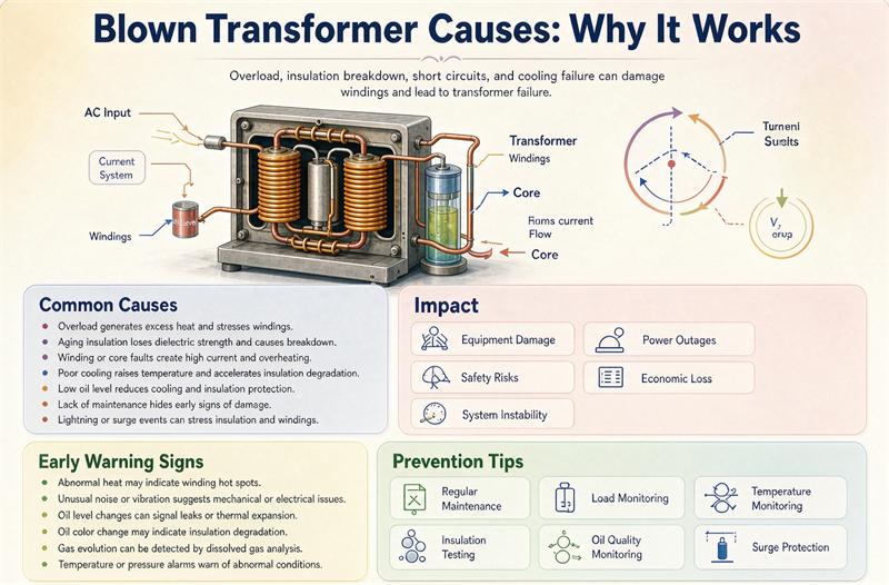
A blown transformer is almost always the end of a chain, not a random event. The short version: sustained overload or a short circuit heats the windings, the insulation breaks down, an arc forms, and in an oil-filled unit the vaporizing oil builds pressure until the tank vents or ruptures. Insulation and thermal failure are the single largest group of causes. Everything else, lightning, moisture, cooling loss, and age, just speeds that chain up. If you are specifying a unit, TransNine Electric can help you match rating, cooling, and protection to the job.
This guide walks through what actually happens inside a failing transformer, the eight causes buyers run into most, the warning signs you can catch early, and the items you should write into a specification so the unit resists failure in the first place.
The failure chain in plain terms
Most catastrophic failures follow the same domino sequence. Understanding it helps you see why the “causes” below are really just entry points into one process.
- Stress appears. A load grows, a fault occurs, a surge arrives, or cooling drops.
- Heat builds. Copper and core losses rise, and the winding hot spot climbs past its design limit.
- Insulation ages faster. Paper, resin, or oil lose dielectric strength with every hot day.
- Partial discharge starts. Tiny arcs inside voids eat the insulation from within.
- A hard fault forms. A turn-to-turn or winding-to-ground short appears.
- Energy releases. The arc vaporizes oil (in oil units) or overheats resin (in dry units).
- Pressure or fire. In oil-filled transformers the gas pushes the tank toward its relief device or past it.
The lesson for buyers: you rarely prevent “explosions.” You prevent step 1 and step 2. Almost every cause below is a way to get heat or voltage stress into the box early.
Eight causes at a glance
The table ranks causes by how often field and maintenance surveys group them together. Exact percentages shift by fleet and region, but the ordering is consistent: thermal and insulation related failure is the largest single group.
| Cause | What actually happens | Relative frequency | Primary defense |
|---|---|---|---|
| Sustained overload and overheating | Load above rating raises the hot spot, cooking insulation | High | Correct kVA sizing, load monitoring |
| Insulation deterioration | Heat, moisture, and age drop dielectric strength | High | Thermal class matched to site, DGA |
| Short-circuit faults and forces | Fault current bends windings and punctures insulation | Medium | Short-circuit withstand rating, relays |
| Lightning and switching surges | Transient overvoltage punches through insulation | Medium | BIL rating, coordinated surge arresters |
| Cooling-system failure | Fans, pumps, or radiators stop shedding heat | Medium | Redundant cooling, temperature alarms |
| Moisture and contamination | Water and particles cut oil and solid insulation strength | Medium | Sealed design, oil tests, desiccant |
| Manufacturing defects | Weak joints, contaminated oil, mis-wound coils | Low | FAT test reports, type-test certificates |
| Skipped maintenance | Small faults grow unseen into big ones | Medium | Condition monitoring, PM schedule |
Cause 1: sustained overload and overheating
A transformer is rated in kVA for a reason. Draw more current than the rating allows and the I squared R losses turn into heat faster than the cooling system can remove it. The winding hot spot climbs, and insulation that was good for years ages in months.
The numbers buyers should know: insulation thermal classes set the winding hot-spot ceiling above ambient, Class A 105 degrees C, Class B 130, Class F 155, Class H 180. IEEE C57.91, the loading guide, treats 110 degrees C hottest-spot as the normal continuous limit and 120 degrees C as the short-term emergency limit, with top-oil limits of 95 and 105 degrees C. Run a unit near or past those limits and you are buying a failure.
A practical trap: sites add equipment, electric vehicle chargers, new lines, extra chillers, without rechecking the transformer. A unit sized for 500 kVA strains and fails when the site quietly grows to 650 kVA. For harmonic-heavy loads such as VFDs, UPS, and LED lighting, use a K-factor rated unit and size with a data-center transformer calculator that accounts for non-linear heating.
Cause 2: insulation deterioration
Insulation is the transformer’s first and only wall between live parts. It fails slowly. Heat cycles dry and embrittle cellulose and resin. Moisture lowers breakdown voltage. Electrical stress grows micro-voids that become partial discharge sites. Once discharge starts, the decline accelerates.
Two buyer actions matter. First, pick a thermal class matched to the environment, not the cheapest one. A unit in a hot, enclosed electrical room needs Class F or H headroom. Second, watch the oil or the resin. In oil-filled units, dissolved gas analysis, DGA, is the early-warning system. IEC 60599 coding gives indicative attention levels: acetylene appearing at all points to arcing, ethylene climbing past about 100 to 150 ppm suggests overheating above 300 degrees C, and hydrogen above roughly 100 to 150 ppm suggests corona or partial discharge. These are starting points; confirm against your lab’s thresholds.
Cause 3: short-circuit faults and electromagnetic forces
A short circuit on the secondary or primary injects a current many times the rating. The electromagnetic force between windings scales with the square of that current, so a modest rise in fault current means a large rise in mechanical stress. Windings can deform, shift, or collapse, and a deformed winding shorts internally days or years later.
A 1000 kVA, 480 V unit with 5.75 percent impedance sees a terminal fault current near 20.9 kA and a peak asymmetrical current around 4.6 kA. That is the force the structure must survive. Short-circuit withstand is a mandatory type test under IEEE C57.12.90, so ask for the certificate, not just a promise. For protection coordination and fault-current checks on your own system, use the NEC protection and fault-current calculator.
Cause 4: lightning and switching surges
A nearby lightning strike or a utility switching event puts a transient overvoltage on the line that can exceed what the insulation was built to absorb. The insulation coordination value is the basic impulse level, BIL. Typical examples: a 15 kV class winding is built to 95 kV BIL, a 25 kV class to 125 kV, and a 34.5 kV class to 200 kV. Surge arresters sized below the BIL clamp the spike before it reaches the windings. Arresters limit, they do not erase, so coordinate the arrester rating to the BIL and keep grounding tight.
Cause 5: cooling-system failure
Heat is the constant enemy, and cooling is how you beat it. In oil-filled units, low oil level, blocked radiators, failed pumps, or stuck fans stop heat removal. In dry-type units, blocked ventilation, dust on the coils, or a failed forced-air fan do the same. Both paths end at the same place: a climbing hot spot.
Specify redundancy where downtime hurts. Forced-air, AF, taps or ONAN/ONAF stages let a unit keep running at reduced load if one fan fails, and temperature sensors should alarm before damage. Keep the unit in a clean, dry, ventilated space per the manufacturer and NEMA guidance.
Cause 6: moisture and contamination
Water is brutal on insulation. It drops the dielectric strength of both oil and solid insulation and invites partial discharge. Contamination, conducting particles, water, and degraded oil, does the same. Sealed and nitrogen-blanketed designs resist moisture entry; open vents need working desiccants.
Buyers should specify oil dielectric strength, BDV, and moisture limits in acceptance and track them. A falling BDV or rising moisture reading is a leading indicator of trouble long before a failure.
Cause 7: manufacturing defects and poor installation
A weak solder joint, a contaminated oil batch, a mis-wound coil, or a loose connection left uncorrected can seed a failure years later. This is why factory acceptance testing and clean commissioning matter. Require routine-test reports, and for the critical units, type-test certificates, differential protection, and proper grounding at installation. Skipped or sloppy commissioning is a defect you pay for later.
Cause 8: skipped maintenance and condition monitoring gaps
A large share of in-service failures trace back to deferred care. Insulation, gaskets, connections, and tap changers all wear. A unit with no inspection program, no thermal scan, no tested connections, and no oil or DGA trend ages faster than its design life. Proactive replacement of an aging unit is almost always cheaper than emergency replacement after an unplanned blow.
Dry-type versus oil-filled: how failure and explosion risk differ
This is the question buyers in hospitals, data centers, and high-rises care about most. The mechanism is different by design.
| Aspect | Oil-filled transformer | Dry-type transformer |
|---|---|---|
| Flammable liquid | Yes, mineral or ester oil | No liquid, air or resin |
| Explosion or fireball mechanism | Oil vaporizes and can ignite under arcing | None, no liquid to vaporize |
| Typical failure modes | Oil degradation, gas, leaks, tank pressure | Resin cracking, moisture ingress, blocked ventilation, harmonic heating |
| Where codes push it | Outdoor, substation, large power | Indoor, occupied buildings, data centers |
| Main defenses | DGA, Buchholz, pressure relief, sealing | Ventilation, IP rating, K-factor, thermal class |
Dry-type units are not failure-proof. Block the airflow or load them with harmonics and they overheat too. They simply remove the flammable-liquid mechanism that produces the dramatic fireball. That is why building codes and the NEC steer dry-type into spaces where a fire is unacceptable. For real deployments we have shipped, see our data-center and solar project cases.
Warning signs before a transformer fails
Most failures are preceded by detectable signals. Catching them turns a catastrophe into a scheduled repair.
| Warning sign | What it usually means | Action |
|---|---|---|
| Rising oil temperature or load | Overload or cooling loss | Check load, fans, oil level |
| DGA acetylene or rising ethylene | Arcing or overheating | Lab retest, plan inspection |
| Partial discharge activity | Insulation voids | Monitor, schedule intervention |
| Oil leaks | Lost insulation and cooling, moisture entry | Repair seal, test oil |
| Unusual buzzing or crackling | Loose core or internal fault | Investigate, de-energize if severe |
| Frequent trips, Buchholz, or pressure-relief operation | Internal fault | Isolate and inspect |
| Discoloration or burning odor | Local hot spot | Thermal scan, reduce load |
How to specify a transformer that resists failure
This is the part most articles skip and the part that protects your budget. Write these into the specification.
- Size with headroom from a real load study, not a guess, and include harmonic and growth margin.
- Match the thermal class, F or H, to the site temperature and enclosure.
- Require an IP and IK rating suited to the environment, especially coastal, dusty, or outdoor sites.
- Specify condition monitoring: RTD sensors, DGA ports on oil units, Buchholz relay, and pressure-relief device.
- Require a short-circuit withstand certificate to IEEE C57.12.90.
- Set the BIL and pair it with coordinated surge arresters.
- Size forced-air or ONAN/ONAF cooling for the worst-case ambient, not the average.
- Specify a quality on-load tap changer only if you truly need voltage regulation.
- Build a maintenance and spare-parts plan before energization.
- Pick an efficiency tier with a loss and total-cost-of-ownership calculator, because losses are a 30-year cost and a heat source you control at purchase.
Browse the full product range to see how these options map onto real ratings and enclosures.
Standards that cover failure prevention and testing
Buyers do not need to memorize these, but they should appear in the specification and test reports.
- IEEE C57.91, loading guide, the hot-spot and top-oil limits above come from here.
- IEEE C57.12.90, routine and type tests including short-circuit withstand.
- IEEE C57.104, guide for DGA interpretation.
- IEEE C57.96, installation and maintenance guidance.
- IEC 60076 series, the international equivalent for design and testing.
- IEC 60599, DGA coding and interpretation.
- IEC 60296, specification for new insulating oil.
- NEMA TR and ST standards for dry-type and pad-mounted units.
- NFPA 70, the NEC, Article 450 covers transformer installation and protection.
More buying guides sit in our resources library.
Common myths
- “Transformers explode randomly.” No. It is a fault chain you can interrupt early.
- “Bigger is always safer.” Oversizing raises no-load losses and cost and can hurt voltage regulation. Size it right with margin.
- “Dry-type never fails.” It fails differently, through heat and ventilation, not through fire.
- “A surge arrester makes lightning impossible.” It limits the spike; it does not remove the risk. Coordinate it to the BIL.
Wrapping up
A blown transformer is the visible end of a preventable chain. Insulation and thermal failure lead the list, short circuits and surges supply the sudden hits, and skipped maintenance lets small faults grow. Specify for the chain, not the blast: right kVA with margin, the right thermal class, real monitoring, a short-circuit withstand certificate, coordinated surge protection, and a maintenance plan. Do those and the dramatic failure becomes a line item you never have to explain.
FAQ
What does “blown transformer” actually mean? It describes a catastrophic failure, usually an internal fault with arcing, not a literal explosion in most cases. In oil-filled units the arc can vaporize oil and rupture the tank; in dry-type units the same fault overheats resin without a fireball.
What is the most common cause of transformer failure? Field and maintenance surveys group thermal and insulation related failure as the largest single category. Sustained overload raises the winding hot spot past its limit, and insulation ages until it breaks down. Short circuits, surges, cooling loss, and moisture are common accelerants.
Can a transformer explode? Oil-filled transformers can, because arcing vaporizes flammable oil and builds tank pressure. Dry-type transformers have no liquid, so the fireball mechanism does not exist by design. Both can still fail internally from heat and electrical faults.
What temperature is too hot for a transformer? Use the winding hot-spot limit, not the room temperature. IEEE C57.91 treats 110 degrees C hottest-spot as normal continuous and 120 degrees C as emergency, with top-oil limits of 95 and 105 degrees C. Insulation classes set the ceiling: Class F 155 degrees C, Class H 180 degrees C above ambient.
Does a bigger kVA rating prevent failure? Not by itself. Oversizing adds no-load losses, cost, and can worsen voltage regulation. The right answer is a load study with harmonic and growth margin, then a thermal class and cooling scheme matched to the site.
How does a short circuit damage a transformer? The fault current creates electromagnetic force between windings that scales with the square of the current. A 1000 kVA, 480 V unit at 5.75 percent impedance sees about 20.9 kA and a 4.6 kA peak, enough to bend or shift windings. Short-circuit withstand is a mandatory IEEE C57.12.90 type test.
What warning signs show a transformer is about to fail? Rising oil temperature or load, DGA acetylene or climbing ethylene, partial discharge, oil leaks, unusual buzzing or crackling, frequent breaker or Buchholz trips, and burning odors or discoloration. Catching these turns a blow into a scheduled repair.
Which standards cover failure prevention and testing? IEEE C57.91 for loading, C57.12.90 for tests including short-circuit withstand, C57.104 for DGA, C57.96 for installation, IEC 60076 and IEC 60599 internationally, plus NEMA and the NEC Article 450.