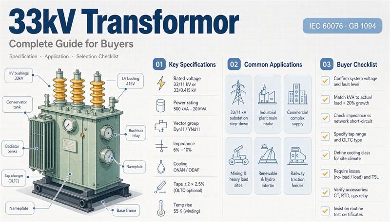
A 33 kV transformer steps a 33,000 volt network down to something usable, usually 400 V or 415 V for a plant, or 11 kV for a sub-transmission bus. It also runs the other way, lifting 690 V or 800 V from solar and wind inverters up to 33 kV for collection.
Here is the thing nobody puts in the buying guide: on a 1,000 kVA unit, the electricity you pay for in losses over 30 years comes to somewhere between $38,000 and $58,000. The transformer itself, going by published price tables, lands somewhere between $9,000 and $18,000. You are buying a machine whose running cost is several times its sticker price, and almost every quote you receive will be built around the sticker price.
That gap is the whole game. This guide covers what 33 kV actually means on a nameplate, the three different insulation schedules hiding behind the words “about 33 kV,” the amps and fault currents that set your switchgear budget, what published price tables agree and disagree on, how much a 33 kV unit weighs, and the exact block of text to paste into an RFQ. All numbers are worked out from published manufacturer data, and every place where we did our own arithmetic is marked as such.
What “33 kV” means on the nameplate (it is not 33)
33 kV is the system nominal voltage. The number that goes on the equipment rating is the highest voltage for equipment, written Um, and for a 33 kV system that is 36 kV.
That distinction is not pedantry. Insulation levels, clearances, bushing selection and the dielectric tests your unit has to survive are all indexed on Um, not on the nominal system voltage. Per the insulation table reproduced in the Energypac power and distribution transformer catalogue (which cites IEC 76-3 Clause 5, Table II), at Um = 36 kV:
- Rated short-duration power-frequency withstand voltage: 70 kV rms
- Rated lightning impulse withstand voltage: 145 kV peak (List 1) or 170 kV peak (List 2)
Two lists, two numbers. List 1 is the lower one, and it is the one most quotes default to unless you ask. If your site has real lightning exposure, a long exposed overhead feeder, or a coastal or high-altitude location, say so in the inquiry and name the list you want. The same catalogue notes plainly that higher withstand requirements “must be stated in the inquiry and may result in a higher price.”
Where 33 kV sits in the family: IEC 60038 runs 11 kV / 22 kV / 33 kV, and 33 kV is the top of the distribution range, below sub-transmission at 66 kV and 110 kV. It is the standard choice when 11 kV would need too many substations to cover a large site and 66 kV would be overkill for the load.
Common configurations:
- 33/0.4 kV or 33/0.415 kV step-down, feeding an LV board directly. This is the industrial and commercial workhorse.
- 33/11 kV step-down at a utility or large-campus intake substation.
- 0.69 kV or 0.8 kV to 33 kV step-up for solar and wind collector systems.
Three insulation schedules hide behind “about 33 kV”
This is where buyers get quietly mismatched equipment. Three standards families all cover roughly this voltage, and they do not ask for the same dielectric performance.
| World | Nominal system | Highest voltage Um | Lightning impulse (LI) | Power-frequency withstand |
| IEC (Europe, Africa, Asia, Australia) | 33 kV | 36 kV | 145 kV (List 1) / 170 kV (List 2) | 70 kV rms |
| GB (China domestic) | 35 kV | 40.5 kV | 200 kV (185 kV internal) | 85 kV external / 80 kV internal |
| ANSI/IEEE (North America) | 34.5 kV | 38 kV (switchgear max) | 200 kV standard for liquid-immersed distribution; 150 kV and 125 kV also in common use | see C57.12.00 tables |
Sources and caveats, because this table is doing a lot of work:
- The IEC row comes from the Energypac catalogue reproducing IEC 76-3 Clause 5, Table II. We did not read the IEC text directly. Confirm against the edition named in your contract.
- The GB row comes from Chinese insulation coordination tables published on bjx.com.cn and in a Ministry of Housing notice reproduction (both citing the DL/T 620 and GB 311.1 family), cross-checked against a manufacturer data page for a 35 kV wind-farm compact substation that lists 40.5 kV maximum operating voltage, 200 kV impulse peak and 85 kV active-part power-frequency withstand. Three sources agree on 40.5 / 200 / 85.
- The ANSI row comes from the Voltimum power distribution systems reference, Tables 1.1-4 and 1.1-5, which reproduce ANSI/IEEE C57.12.00 and IEEE C37.74 values. In that table the bolded “standard” BIL for a 34.5 kV liquid-immersed distribution transformer is 200 kV, with 150 kV and 125 kV listed as also in common use. Separately, 38 kV rated-maximum-voltage pad-mount switchgear per IEEE C37.74-2014 is listed at 150 kV impulse.
Two practical consequences:
The 35 kV catalogue label is not a 33 kV design. A page that says 35 kV is usually describing the GB family, built to Um 40.5 kV with a 200 kV impulse schedule. Your IEC 33 kV project is Um 36 kV. They are close enough that a supplier will happily quote one for the other, and different enough that bushings, creepage distance and test voltages differ. We could not verify a single authoritative equivalence mapping between the two, so do not accept one. Ask which Um the offered design is built and tested to, and require the test certificate to show it. If your project really is 35 kV rather than 33 kV, start from our 35 kV large-capacity oil-immersed ratings and specification guide rather than treating it as a substitute.
Altitude changes external insulation. Above 1,000 m the air gets thinner and external clearances need correction. Do not accept a standard unit for a 2,400 m site and hope for the best. Make the supplier state the correction method and the resulting clearances in writing.
The 11 spec lines that actually move the price
Every 33 kV quote comes back to the same handful of inputs. Here is what each one does and what to write.
| Input | What it changes | What to write in the inquiry |
| Rated kVA | Core size, conductor, price, losses | Number, plus your load profile and diversity factor |
| Full voltage ratio and Um | Insulation, bushings, test schedule | e.g. 33/0.415 kV, Um 36 kV / 1.1 kV |
| Frequency | Core design, cooling, losses | 50 Hz or 60 Hz, stated explicitly |
| Vector group | Harmonics, earthing, paralleling | Dyn11, Yyn0, YNd11, as the single-line dictates |
| Impedance % | Fault current, voltage regulation, price | Number with tolerance |
| Tap changer | Construction, controls, price | Off-circuit ±2×2.5%, or OLTC with range and steps |
| Cooling class | Rating, fans, controls | ONAN, ONAF, AN, AF |
| Winding material | Losses, short-circuit strength, price | Copper or aluminium, stated per winding |
| Ambient and altitude | Thermal design, clearances | Max ambient °C, site altitude in metres |
| Enclosure and IP | Tank, kiosk, corrosion protection | Indoor/outdoor, IP code, coastal treatment if needed |
| Standards and test scope | Documentation you can defend later | IEC 60076 with parts, plus named routine and type tests |
Three of these deserve more than a row.
Vector group. Dyn11 is the default for 33/0.415 kV distribution, and for a reason: the delta-connected HV winding gives third-harmonic currents somewhere to circulate instead of pushing them back into the network, and the star LV side gives you a neutral. Yyn0 is only defensible for genuinely balanced three-phase loads. One trap worth knowing: ANSI/IEEE C57.12.00 requires the low-voltage side of a delta-wye unit to lag the high-voltage side by 30 degrees, which is Dyn1 in IEC notation, while IEC markets normally specify Dyn11. Same machine family, different clock number. If you are exporting into an IEC grid or importing into an ANSI one, name the group rather than assuming.
Impedance. For this class you will see roughly 4% at the small end and 6% to 8% once you get past about 800 kVA, with 6.25% common on 33/11 kV power transformers. Runsheng’s 33 kV guide quotes “6 to 8 percent” for the class. Impedance is the lever that sets your downstream fault current, and it is also a price lever, because lower impedance means more copper and a stronger mechanical design. Ask for the value with its tolerance. IEC allows a tolerance band, and a supplier quoting “6%” can deliver 6.5%.
Tap changer. “Tap changer” is one phrase describing two very different machines. An off-circuit tap changer (also called DETC or NLTC) is adjusted during a planned outage, costs little, and is the right answer for a stable grid. An on-load tap changer (OLTC) adjusts under load, needs a motor drive, controls, auxiliary supply and a maintenance regime, and costs materially more. Jinxing’s selection guide makes the point well: both documents can contain the phrase “tap changer” while describing completely different scope. Specify the method, the range, the number of steps, and who owns the control signal.
Amps, and where the switchgear wall is
Two formulas cover everything in this section.
- Three-phase current: A = kVA × 1,000 ÷ (√3 × volts)
- Which gives these handy multipliers: 33 kV side: A = kVA × 0.017495. 11 kV side: × 0.05249. 415 V side: × 1.3913. 400 V side: × 1.4434. 690 V side: × 0.8368.
33 kV side current
| kVA | Amps at 33 kV |
| 250 | 4.4 |
| 500 | 8.7 |
| 800 | 14.0 |
| 1,000 | 17.5 |
| 1,600 | 28.0 |
| 2,000 | 35.0 |
| 2,500 | 43.7 |
| 3,150 | 55.1 |
| 5,000 | 87.5 |
| 10,000 | 175.0 |
A 1,000 kVA 33 kV transformer draws 17.5 A on the primary. That is a number worth internalizing, because it tells you something important about the MV side.
The 33 kV switchgear rating does not come from your transformer
Divide that current by the impedance and you get the transformer’s own contribution to a fault at its terminals. For 1,000 kVA at 6%, that is 17.5 ÷ 0.06 = 0.29 kA. For 5,000 kVA at 6%, it is 1.46 kA.
Your 33 kV switchgear will be rated somewhere around 25 kA or 31.5 kA. The transformer contributes under 2% of that. The MV switchgear rating is set by the fault level the utility declares at your point of connection, not by your transformer. Ask the utility for the declared fault level in writing, and size the MV gear to that. Your impedance choice barely registers on the MV side.
Where it does register: the low-voltage side
Here is the table nobody publishes. Fault current at the LV terminals, upper bound, using only transformer impedance (Isc = FLA ÷ %Z), at 415 V with the impedance values from a published 33 kV sealed-type specification table:
| kVA | FLA at 415 V | Z | Upper-bound fault current | Gear rating you need |
| 250 | 348 A | 4% | 8.7 kA | 16 kA is plenty |
| 500 | 696 A | 4% | 17.4 kA | 25 kA |
| 630 | 876 A | 4% | 21.9 kA | 25 kA, tight |
| 800 | 1,113 A | 6% | 18.5 kA | 25 kA |
| 1,000 | 1,391 A | 6% | 23.2 kA | 25 kA, and that is the wall |
| 1,250 | 1,739 A | 6% | 29.0 kA | 31.5 kA |
| 1,500 | 2,087 A | 6% | 34.8 kA | 40 kA |
| 1,600 | 2,226 A | 6% | 37.1 kA | 40 kA |
| 2,000 | 2,782 A | 6% | 46.4 kA | 50 kA |
| 2,500 | 3,478 A | 6% | 58.0 kA | 63 kA |
Two things to read off that table.
1,000 kVA is the last comfortable 25 kA machine at 6% impedance. Go to 1,250 kVA and you are at 29 kA and buying 31.5 kA gear. If you are on a 400 V system instead of 415 V, every number goes up by about 3.8%, so 1,000 kVA becomes 24.1 kA, which clears 25 kA by less than a kiloamp. Do not size LV gear off a round number. Run the arithmetic with the actual impedance the supplier guarantees.
These are upper bounds. We ignored source impedance and cable impedance, which pull the real number down. Real bolted fault currents at the LV board typically land somewhat below these figures. Use the table to choose a gear rating, not as the final protective device coordination study, which needs the full network model.
Every number in both tables above is our own arithmetic from the formulas stated, not a value copied out of a standard.
Oil, dry, amorphous, or packaged
Four construction paths, and the decision is usually made by location before anything else.
Oil-immersed is the outdoor default. Series designations you will see are S11, S13, S20 and S22, with cooling as ONAN (natural oil, natural air) or ONAF (forced air for an overload step). It is the lowest cost per kVA, handles overload well, and tolerates rough sites. The trade-offs are oil handling, fire separation, and containment. Our oil-immersed transformer range covers the standard 33 kV ratings.
Dry-type cast resin (SCB10, SCB13, SCB14, SCB18) exists at 33 kV and is the answer for indoor rooms, tunnels, metro, hospitals and data centres where you do not want combustible liquid. It costs more per kVA and its practical ceiling is lower, but it removes the fire and containment problem entirely. See the dry-type range for what is available at this voltage.
One caution if you go dry-type: an IP code is not a climate code. IEC 60076-11 carries a three-part environmental classification (a thermal class C1/C2, a humidity and condensation class E0/E1/E2, and a fire behaviour class F0/F1) that an IP rating does not cover. IP54 tells you about dust and water jets. It does not tell you whether the unit survives a cold, damp, unheated room that sits idle for a week. Specify the C/E/F codes.
Amorphous metal core (SH15, SCBH15) cuts no-load loss sharply, because core loss is paid 24 hours a day whether you are loaded or not. A vendor glossary puts the reduction at roughly 60 to 70% against grain-oriented silicon steel. Compare that with the step from S11 to S13, which Tailong’s guide describes as 20 to 30% lower no-load loss. Two different comparisons, both plausible, and both worth pricing against your own electricity tariff.
Packaged substations put the transformer, 33 kV switchgear and the LV board in one transportable unit. This is the path when site labour is expensive or the programme is tight, and it is very common at 33 kV. We have run multi-unit 11 kV and 33 kV compact substation programmes for overseas utility EPCs; you can see how those get specified and shipped on the projects page. The full product catalogue covers the rest of the range.
What it costs, and the number nobody puts in the table
Let us be honest about price data first. Published transformer price tables are marketing pages. We grade them as low-confidence sources and report them only to show how far apart public claims sit. None of the following is verified pricing, and none of it should go into a budget.
Two published tables, same nominal product class, different answers. For oil-immersed distribution transformers at 1,000 kVA, one 2026 wholesale guide lists $8,200 to $9,500 FOB China. A market analysis of Middle East imports puts the heavily traded 1,000 kVA 11 kV/415 V standard-efficiency unit at $11,000 to $15,000 FOB from Asian manufacturers in 2025 to 2026. That is roughly a 1.2 to 1.8 times spread on the same rating. At 2,000 kVA the same sources give $15,500 to $17,800 FOB against $25,000 to $40,000 landed.
Then two multipliers stack on top:
- Moving from an 11 kV class to a 33 kV class design is described as adding 8% to 20% by one price guide and 10% to 20% by another. The stated reasons are bigger clearances, better winding technology and stricter testing.
- Landed cost versus FOB adds 15% to 25% once freight, insurance and certification are in.
So a 1,000 kVA 33 kV oil unit, on published numbers, plausibly lands somewhere in the $9,000 to $18,000 band depending on whose table you start from and how you apply the two multipliers.
Lead time is the number nobody publishes. Four manufacturers answered this in public product Q&A, and their answers span 15 to 90 days: one quotes 25 to 35 working days standard and 35 to 50 custom, another 15 to 25 days standard and 25 to 40 custom, a third 15 to 30 days standard and 45 to 90 for large or custom, a fourth 15 to 25 days standard and 30 to 45 for custom or large. A six-fold spread on the same question. Get it in writing and make them split it into drawing approval, manufacturing and shipping, because those three slip for different reasons and only one of them is the factory’s fault.
The number that should actually drive the decision
Here is the calculation that every guide tells you to do and none of them does.
Take a 1,000 kVA 33 kV unit. Published datasheets disagree about what it loses:
| Source for a 1,000 kVA 33 kV unit | No-load loss | Load loss | Loss at 50% load | kWh/year | 30-year present value |
| Fuji Tusco 33 kV sealed specification table | 2,000 W | 13,500 W @ 75 °C | 5,375 W | 47,085 | $58,428 |
| Hero Transformer 1,000 kVA 33/0.4 kV | 1,230 W | 9,369 W | 3,572 W | 31,293 | $38,831 |
| Eltranff 1,000 kVA 33/0.415 kV listing | 1,400 W | 12,250 W | 4,462 W | 39,092 | $48,509 |
Assumptions, stated so you can change them: 8,760 hours a year, $0.10 per kWh, 30 years discounted at 7% (present value factor 12.409), operating at 50% average load. Load loss scales with the square of load, so at 50% load you pay a quarter of the load loss figure. This is our arithmetic.
The spread between the two most divergent published datasheets for the same rating is $19,597 in 30-year present value. That is more than the entire purchase price of the transformer, and it exists purely because nobody asked for guaranteed losses with tolerances.
Set that against the purchase price band above and the ratio lands between roughly 2 times and 6.6 times. The machine is cheaper than its own electricity.
Two more things fall out of the same numbers
Peak efficiency is nowhere near full load. The load factor at which a transformer is most efficient is the square root of (no-load loss ÷ load loss). For those 1,000 kVA datasheets that works out to 31.6% to 38.5% of rated load. Tailong’s selection guide advises designing for 70% to 85% loading “for best energy efficiency,” and that is a capacity-headroom rule, not an efficiency rule. At 75% load on the Fuji numbers, losses are 9,594 W against 3,998 W at the 38.5% sweet spot. Per delivered kVA, the lightly loaded machine is doing better. Size for headroom if you want the headroom, but do not tell yourself it is the efficient choice.
Amorphous payback is short on continuously energized sites. The no-load difference between the best and worst published 1,000 kVA figures above is 850 W. Running 24/7 at $0.10/kWh, that is 7,446 kWh a year, $745 a year, and **$9,240 in 30-year present value**. Against a typical amorphous premium of 15% to 25% on a $9,000 to $18,000 machine, that is $1,350 to $4,500, so simple payback lands somewhere between roughly 2 and 6 years on a unit that stays energized all the time. On a lightly loaded standby unit, it never pays back.
Weight, size, oil volume, and whether it fits through the door
From the same published 33 kV sealed-type specification table, hermetically sealed construction:
| kVA | Total weight | Height | Length | Width | Oil |
| 500 | 1,900 kg (4,189 lb) | 1,650 mm (65.0 in) | 1,500 mm (59.1 in) | 900 mm (35.4 in) | 500 L |
| 1,000 | 3,350 kg (7,385 lb) | 1,900 mm (74.8 in) | 1,950 mm (76.8 in) | 1,100 mm (43.3 in) | 750 L |
| 1,250 | 4,150 kg (9,149 lb) | 2,000 mm (78.7 in) | 2,000 mm (78.7 in) | 1,150 mm (45.3 in) | 900 L |
| 1,500 | 4,300 kg (9,480 lb) | 2,100 mm (82.7 in) | 2,100 mm (82.7 in) | 1,250 mm (49.2 in) | 1,200 L |
| 2,000 | 5,800 kg (12,787 lb) | 2,200 mm (86.6 in) | 2,250 mm (88.6 in) | 1,350 mm (53.1 in) | 1,450 L |
| 2,500 | 6,600 kg (14,550 lb) | 2,350 mm (92.5 in) | 2,450 mm (96.5 in) | 1,450 mm (57.1 in) | 1,750 L |
Read three things off it.
The door. A standard personnel door is about 80 inches. A 1,000 kVA 33 kV unit at 74.8 inches clears it with five inches to spare, which is not enough margin once you add a pallet or a skid. Anything from 1,500 kVA up does not go through a normal door at all, and neither does a 1,250 kVA unit by much. Measure the route before you order, not after the truck arrives.
The crane. Even the 500 kVA unit is over 4,000 lb. Everything on this table needs mechanical lifting and a route that can take it. Check the laydown area can carry the point load.
The oil. Converted to US gallons, 1,000 kVA holds about 198 gallons and 2,000 kVA about 383 gallons. If your site falls under the US EPA Spill Prevention, Control and Countermeasure rule, oil-filled electrical equipment counts toward the 1,320 gallon aggregate threshold for aboveground oil storage, and that threshold applies per facility, not per tank. On those numbers, seven 1,000 kVA units or four 2,000 kVA units put you over the line and into a written SPCC plan. Confirm the rule text and your own applicability rather than taking a round number from us.
Paste this into your RFQ
Send this alongside a single-line diagram, and mark anything unknown for confirmation rather than filling it in with a guess.
Line 12 is the one that changes the outcome. A quote that will not state guaranteed losses in watts with a tolerance is a quote you cannot evaluate.
If your project is 60 Hz or North American
33 kV is essentially absent from North American distribution. 34.5 kV is what you will find there, and it is a different standards world.
- Class naming. ANSI groups by insulation class rather than exact operating voltage: 15 kV class covers 12.47 and 13.8 kV, 25 kV class covers 24.94 kV, and 35 kV class covers 34.5 kV. Switchgear expresses the same tiers as rated maximum voltages of 15, 27 and 38 kV.
- BIL. Per the Voltimum reproduction of ANSI/IEEE C57.12.00, a 34.5 kV liquid-immersed distribution transformer carries a listed standard BIL of 200 kV, with 150 kV and 125 kV also in common use. Switchgear at 38 kV rated maximum voltage is listed at 150 kV impulse. Note that an IEC 33 kV unit quoted at the List 1 minimum of 145 kV sits below both.
- DOE efficiency rules. The US Department of Energy efficiency standards for distribution transformers live in 10 CFR 431 subpart K and apply to 60 Hz units with a primary of 34.5 kV or below and a secondary of 600 V or below, covering liquid-immersed 10 to 5,000 kVA and dry-type 15 to 5,000 kVA. A 33 kV primary is inside the input voltage limit, but a 50 Hz, 415 V secondary IEC package does not map onto it. Do not assume your IEC unit is covered or exempt without checking the scope clause.
- Converting a 50 Hz design to 60 Hz. The Energypac catalogue lists four routes a manufacturer can take: raise rated power and impedance by 10% and change nothing else; raise rated power by 20% while accepting 30% higher no-load loss and 3 dB more noise (not available on cast resin); keep all data identical and take roughly a 5% price reduction; or reduce temperature rise by 10 K and load loss by 15%. Four paths, four different machines. Make them tell you which one they are quoting.
- Going the other way is dangerous. A 60 Hz design run on 50 Hz sees roughly 20% more flux, and the supply voltage has to come down in proportion. This is the direction that produces failures.
For a full side-by-side of the two standards families, see our guide on IEC 60076 versus ANSI/IEEE standards for export transformers.
Bottom line
Three things decide whether this purchase goes well.
Name your Um, not just your kV. 33 kV means Um 36 kV, and it means picking between a 145 kV and a 170 kV impulse schedule. A page labelled 35 kV is a different design built to 40.5 kV. Make the supplier state which one they are building and make the test certificate show it.
The loss bill dwarfs the invoice. On a 1,000 kVA unit, our arithmetic on published datasheets puts 30 years of losses between about $38,000 and $58,000 against a purchase price somewhere between $9,000 and $18,000. The spread between two honest datasheets is worth more than the machine. Buy on guaranteed watts with tolerances.
Impedance is an LV switchgear decision, not an MV one. Your transformer contributes under 2% of a typical 33 kV fault level, so MV gear comes from the utility’s declared fault level. On the LV side, 1,000 kVA at 6% is the last comfortable fit inside 25 kA gear, and 1,250 kVA busts it. Run that arithmetic with the impedance you are actually being sold.
Everything else on this page is detail. Those three change the outcome.
FAQ
Is 33 kV medium voltage or high voltage?
Terminology varies by market and by standard. In IEC usage 33 kV sits at the top of the distribution range, below sub-transmission at 66 and 110 kV. In North American usage it would be a distribution class voltage. The label matters less than the actual system values: state your nominal voltage, your Um, and the standard you are designing to, rather than arguing about the category name.
What is Um, and why is it 36 kV for a 33 kV system?
Um is the highest voltage for equipment, the value insulation levels, clearances and dielectric tests are indexed on. A 33 kV nominal system has Um of 36 kV. Equipment has to be rated for the highest voltage it can see, not the nominal one.
Should I specify 145 kV or 170 kV lightning impulse?
Both are listed for Um 36 kV in the IEC insulation table, as List 1 and List 2. 145 kV is the lower figure and the usual default. Go higher for long exposed overhead feeders, high lightning incidence, coastal pollution or high altitude, and say so in the inquiry, because it affects price.
Can I use a 35 kV transformer on a 33 kV system?
Not without checking. A 35 kV designation usually refers to the Chinese GB family at Um 40.5 kV with a 200 kV impulse schedule, while your IEC 33 kV system is Um 36 kV. They are not interchangeable by assumption. Ask which Um the offered design is built and tested to.
What kVA do I need?
Size from a load study: connected load, demand factor, diversity, and the expansion you actually plan.Then, before you fix the rating, check what impedance does to your LV fault current, because that can change which rating is cheapest to install. A rule of thumb in place of a load schedule is the most common cause of a disappointing purchase.
Copper or aluminium windings?
Copper costs more, has lower losses, better short-circuit strength and a longer service life. One 2026 price guide puts the copper premium at 15% to 30%, another at 30% to 50%. Aluminium is defensible where first cost dominates and the unit runs lightly loaded. On a heavily loaded industrial feeder, copper normally wins on lifecycle cost.
How much does a 33 kV transformer weigh?
Around 3,350 kg (7,385 lb) at 1,000 kVA and 5,800 kg (12,787 lb) at 2,000 kVA for sealed oil-immersed construction, per one published specification table. Every unit on that table needs mechanical lifting, and anything above about 1,250 kVA will not pass through a standard 80 inch door.
What is the lead time?
Published answers from four manufacturers range from 15 to 90 days depending on whether the unit is a standard rating or custom. Get it in writing and split into drawing approval, manufacturing and shipping.
Do I need an on-load tap changer?
Only if your source voltage moves enough to matter and you cannot take an outage to correct it. An off-circuit tap changer is far cheaper and is the right answer on a stable grid. If you do need an OLTC, specify the range, the step size, the control interface and who owns the control signal.
Why do two quotes for the same kVA have such different loss figures?
Because losses are a design choice, not a fixed consequence of the rating. Core steel grade, flux density, conductor cross-section and winding material all move them, and IEC permits a tolerance on guaranteed values. The fix is to require guaranteed no-load and load loss in watts at a stated reference temperature with the tolerance named, then capitalize the numbers and compare.
What tests should every unit pass before shipment?
Routine tests per IEC 60076-1 cover winding resistance, voltage ratio and vector group check, impedance voltage and load loss, no-load loss and current, separate-source and induced voltage withstand, and for oil units the oil dielectric tests. Type tests cover temperature rise, lightning impulse and short-circuit withstand. Ask which routine tests are included and which type test reports exist for the offered design.
How do I compare two quotes fairly?
Normalize them first: same kVA, same impedance with tolerance, same vector group, same winding material, same loss guarantees at the same reference temperature, same test scope, same packing and delivery terms. Then capitalize the losses. Quotes that have not been normalized are not comparable, and the cheaper one is frequently the more expensive machine.