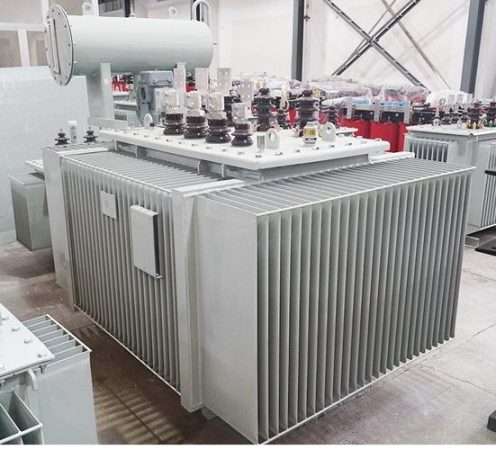
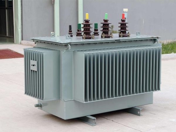
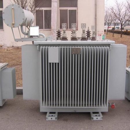
An S18-1000 kVA/10/0.4 kV transformer is a three-phase, oil-immersed distribution transformer that steps 10 kV medium voltage down to 400 V/230 V low voltage and delivers 1,000 kVA continuously. In practice that means about 57.7 A on the 10 kV side and about 1,443 A on the 400 V side, enough real power for a mid-size plant, a shopping centre, a hospital block, or a residential district main substation. This page decodes every element of the model designation, lists the nameplate parameters you should expect, translates the rating for North American 60 Hz systems, and answers the questions buyers actually ask before issuing an RFQ.
Read this before you quote the numbers below. Three items in the source document need checking against the type-test report rather than being repeated. (1) S18 is not a codified efficiency tier in GB 20052-2020 the way S13, S20 and S22 are — ask which grade the unit is actually labelled and request the label filing number. (2) The source states a sound level below 50 dB(A) for a 1,000 kVA ONAN unit; typical measured values for oil-immersed units of this size sit in the 55–65 dB(A) range, so treat 50 dB(A) as a project-specific target rather than a series default. (3) The source lists the cooling classes as AN and AF, which are the IEC 60076-11 designations for dry-type transformers; an oil-immersed unit uses ONAN / ONAF. Section 7 explains why the distinction changes what you order.
1. What the Designation Actually Says
Read the model string left to right. Every character carries a commitment you will be held to at commissioning.
| Element | Value in this model | What it means |
|---|---|---|
| S | Three-phase | Power (as opposed to rectifier, furnace or traction) transformer, three-phase construction |
| 18 | Loss-tier code | Designates a loss level lower than the older S11 and S13 series; confirm which GB 20052 grade it is filed under |
| 1000 kVA | Rated capacity | Continuous apparent power at rated voltage, rated frequency and the specified cooling class |
| 10 kV | HV (primary) rated voltage | Line-to-line voltage on the winding connected to the MV feeder |
| 0.4 kV | LV (secondary) rated voltage | 400 V line-to-line, 230 V line-to-neutral, the IEC low-voltage standard |
Apparent power in kVA relates to real power by the power factor: kW = kVA × PF. At PF 0.9 a 1,000 kVA unit supplies roughly 900 kW of real load; at PF 0.8, about 800 kW. That is why European and Asian switchgear is sized in kVA and why you should size the transformer from a load study, not from the sum of connected nameplates.
2. Decoding Each Element in Detail
S — three-phase. Straightforward, but confirm it is a distribution-class power transformer and not a special-duty design. If the load includes rectifiers, variable-speed drives, arc furnaces or large PV inverters, the core and winding need a harmonic-duty or K-factor design rather than a standard distribution build.
18 — the loss tier. The source states no-load loss is roughly 20% lower than the S11 series, and positions S18 as newer and more efficient than S13 while noting that S20 and S22 are the current high-efficiency oil-immersed series. Percentages are marketing shorthand; what you buy is watts. Always ask for guaranteed P₀ (no-load loss) and Pₖ (load loss) in watts at rated tap, with tolerances per IEC 60076-1, and for the efficiency label filing.
1000 kVA — capacity. Rated for continuous output at rated voltage and frequency under the specified cooling. It is worth knowing that 1,000 kVA is a standard three-phase rating in both IEC and ANSI/IEEE practice, unlike 800 kVA, which is an IEC-preferred size with no ANSI equivalent (the adjacent North American ratings are 750 kVA and 1,000 kVA). If a project may later be built to North American drawings, 1,000 kVA is the safer number to lock in.
10/0.4 kV — the voltage ratio. The HV winding is rated for a 10 kV system (highest voltage for equipment Um = 12 kV), the LV winding for 400/230 V. Off-load tap changing over ±2 × 2.5% on the HV winding is the usual arrangement, giving you the adjustment range to hold secondary voltage steady as the MV feeder moves.
3. Rated Currents and the Numbers You Can Check Yourself
Everything below follows from I = S / (√3 × U). Run it yourself on any quotation — it is the fastest way to catch a transposed digit.
| Quantity | IEC rating (this model) | North American equivalent |
|---|---|---|
| HV rated current | 1000 / (1.732 × 10 kV) ≈ 57.7 A | 12.47 kV → 46.3 A; 13.8 kV → 41.9 A |
| LV rated current | 1000 / (1.732 × 0.4 kV) ≈ 1,443 A | 480 V → 1,203 A; 600 V → 962 A |
| Real power at PF 0.9 | ≈ 900 kW | ≈ 900 kW |
| Real power at PF 0.8 | ≈ 800 kW | ≈ 800 kW |
| Suggested continuous loading | ≈ 80% of rating, leaving headroom | Same rule |
At roughly 1,443 A you are well past a single cable per phase. Plan for busway trunking or several parallel cable runs, and confirm the LV frame size early — a 1,600 A air circuit breaker or a bolted busway tap-off is the normal landing point, and that dimension drives the switchroom layout more than the transformer footprint does.
The fields that decide whether a quotation is comparable to another — vector group, impedance, losses, cooling class, insulation level — are all set out in our walkthrough of how to read a transformer nameplate and technical parameters.
4. Typical Nameplate Parameters
Values below are the conventional set for a three-phase oil-immersed 10/0.4 kV distribution unit. Bracketed items must come from the actual type-test report.
| Parameter | Typical value for S18-1000/10/0.4 |
|---|---|
| Rated capacity | 1,000 kVA |
| Rated frequency | 50 Hz (60 Hz on request — see section 10) |
| HV / LV rated voltage | 10 kV / 0.4 kV |
| Rated currents | 57.7 A / 1,443 A |
| Vector group | Dyn11 (Yyn0 available on request) |
| Short-circuit impedance (Uₖ) | 4% or 6% confirm the ordered value |
| No-load loss (P₀) | watts from the type-test report |
| Load loss (Pₖ at 75 °C) | watts from the type-test report |
| No-load current (I₀) | percent of rated — confirm |
| Insulation system | Class A (105 °C) for conventional paper/mineral-oil; thermally upgraded paper or ester fluid on request |
| Cooling class | ONAN (oil natural, air natural) |
| Insulation level, HV | 10 kV class: typically LI 75 / AC 28 — confirm; a pairing of LI 75 with AC 35 belongs to a different Um |
| Sound level | dB(A) measured per IEC 60076-10 — see the caution above |
| Enclosure protection | IP23 for outdoor terminal chambers; the tank itself is weatherproof by design |
| Approx. oil volume / total mass | from the outline drawing |
5. Losses, Efficiency and Temperature Rise
The source claims efficiency of 98% or better and a loss reduction of about 20% against S11. At 1,000 kVA that is plausible — modern oil-immersed units at this rating commonly exceed 99% at full load — but efficiency is a derived figure, and it peaks somewhere around 40–60% loading. Never accept a percentage in place of watts. Ask for P₀ and Pₖ, then cost them:
Annual loss energy (kWh) = P₀ × 8,760 + Pₖ × β² × 8,760
  P₀ = no-load loss (kW)   Pₖ = load loss at rated (kW)   β = load factor
Every kilowatt of no-load loss runs 8,760 hours a year regardless of how much load you draw, so at $0.12/kWh one kilowatt of P₀ costs about $1,050 per year. One kilowatt of Pₖ at a 0.6 load factor costs roughly $380 per year. Over a 20-year life those two numbers, not the purchase price, decide what the transformer actually cost you.
On temperature rise: the source gives Class A insulation at 105 °C and a top-oil figure of 45 °C. IEC 60076-2 allows a top-oil rise of 60 K and an average winding rise of 65 K; a 45 K figure is tighter than the international default and should be confirmed against the heat-run test report. If the unit will be specified for a hot climate, say so up front — ambient above 40 °C, high altitude, or enclosure in a poorly ventilated room all require derating, and derating is far cheaper to design in than to retrofit.
If you are weighing the step up to a higher tier, compare the guaranteed watt figures on our S20 series oil-immersed distribution transformer page against the S18 numbers before you decide that the premium is worth paying.
6. Vector Group Dyn11 — and the ANSI Notation Trap
Dyn11 breaks down as follows:
- D — HV winding connected in delta
- y — LV winding connected in star
- n — the star neutral is brought out, giving you a four-wire secondary
- 11 — the clock-hour number: the LV line-to-line phasor sits at the 11 o’clock position, i.e. it leads the HV phasor by 30° (equivalently, lags by 330°)
Two practical consequences. The delta HV winding gives third-harmonic and zero-sequence currents a path to circulate instead of pushing them back into the supply, which is why Dyn11 is the default for four-wire distribution with single-phase loads. And the earthed neutral gives you a stable reference for earth-fault protection on the LV side.
If the project is in North America, write Dyn1, not Dyn11. ANSI/IEEE draw the phasor diagram with the opposite rotation convention, so the same physical connection is labelled Dyn1 on a North American drawing. The transformer is identical; only the notation differs. Getting this wrong on a submittal is a common reason for drawings to bounce. Our comparison of IEC 60076 and ANSI/IEEE standards for export transformers covers the other notation differences that catch buyers out.
7. Cooling Class: ONAN, Not AN/AF
The source lists cooling as “natural cooling (AN) or self-cooled (AF)”. That is a dry-type designation set. Oil-immersed transformers use a four-letter IEC code:
- ONAN — oil natural, air natural. No fans, no pumps. The default for units of this size and the reason maintenance is so light.
- ONAF — oil natural, air forced. Fans push air across the radiator, giving a higher continuous rating from the same tank.
- OFAF / OFWF — forced oil circulation, used on large power transformers rather than 1,000 kVA distribution units.
Specify the class you are buying. A rating quoted on ONAF may be a higher number than the same tank on ONAN, and the fans then become both a maintenance item and a noise source. The full code, including the dry-type AN/AF classes and what each stage buys you, is set out in our guide to transformer cooling classes ONAN, ONAF, AN and AF.
8. Insulation Level, Fluid and Enclosure
Insulation level for a 10 kV winding is normally written LI/AC: the lightning-impulse withstand and the separate-source AC withstand. For a 12 kV Um the conventional pairing is LI 75 / AC 28. In North American practice the same requirements appear as BIL and the applied-potential test under IEEE C57.12.00. Do not mix the two notations on one document.
Insulating fluid. Standard mineral oil is the default. Where fire risk, environmental sensitivity or a local authority pushes back, a natural-ester (FR3-class) fluid or a silicone fluid can be specified — ester also tolerates higher winding temperatures, which buys real overload headroom. Confirm the fluid at RFQ stage because it changes the temperature class, the gasket materials and, for sealed units, the protection philosophy.
Sealed versus conservator. A fully sealed, hermetically sealed tank eliminates oil–air contact and the need for periodic oil filtration, but it also means there is no conservator and therefore no Buchholz relay; overpressure protection is by pressure-relief device instead. If your protection scheme is written around a Buchholz relay, the sealed design will not satisfy it.
Enclosure. IP ratings apply to the terminal chambers and any added enclosure, not to the tank. IP23 is the normal outdoor minimum; where dust or driving rain is a factor, step up or add a weather shelter. For oil-filled equipment outdoors, plan the containment: in the United States the EPA SPCC rule applies once aggregate aboveground oil storage crosses its threshold, and a bund or drip tray is far cheaper to pour with the foundation than to add afterwards.
9. Where a 1,000 kVA 10/0.4 kV Unit Fits
This is the classic mid-size main-distribution rating, and the source’s application list maps cleanly onto it:
- Urban utility distribution substations — MV feeder to LV network, typically ONAN with off-load taps
- Industrial plant main step-down or workshop substations — motor loads, process loads, and the inrush that comes with them
- Commercial buildings, shopping centres, hospitals, schools and campuses — long hours at moderate load factor, which is exactly where low no-load loss pays back
- Airports, rail stations and transport hubs — continuous duty with a premium on reliability and, near terminals, on sound level
- Residential district distribution centres — highly variable load, mostly light overnight and peaked in the evening
- Renewable interconnection — the LV or MV side of a PV or storage plant; for inverter duty, specify harmonic-withstand capability explicitly rather than assuming a standard distribution build covers it
For renewable duty specifically, look at the inverter-duty units supplied for a 50 MW solar PV plant — the design drivers there are harmonics and cyclic loading, not just kVA.
Indoor, fire-sensitive or densely occupied sites are the exception. Before you commit to oil in a basement or inside an occupied building, check the fire-separation and containment requirements against a cast-resin alternative using our guide to oil-immersed versus dry-type transformers.
10. Using This Rating on a North American 60 Hz System
A unit built to 10/0.4 kV at 50 Hz cannot simply be shipped to a US or Canadian site. The differences that matter:
- Primary voltage. North American MV distribution runs at 12.47 kV, 13.8 kV or 34.5 kV, not 10 kV. The winding ratio has to be designed for the system it will be connected to.
- Secondary voltage. Standard US four-wire LV is 480Y/277 V; much of Canada uses 600Y/347 V. 400/230 V is not a North American distribution voltage.
- Frequency. 60 Hz. This must be stated at RFQ stage — the core is cut for a specific frequency and cannot be changed afterwards. At 60 Hz, no-load loss rises slightly for a given flux density, so the guaranteed watt figures must be re-issued for 60 Hz.
- Standards. Design and test to ANSI/IEEE C57.12.00 and C57.12.90 rather than IEC 60076, and confirm whether DOE 10 CFR 430 efficiency compliance applies to the target market and rating.
- Listing. Many AHJs and insurers want UL or cUL listing. That is a design and construction decision made before manufacture, not a paperwork step at the end.
11. FAQ
What does S18 mean compared with S13, S20 and S22?
It is a manufacturer’s loss-tier code indicating a lower-loss design than the older S11 and S13 series. S20 and S22 sit above it in the current line-up. Because S18 is not a codified efficiency grade under GB 20052-2020 in the way S20 and S22 are, ask the manufacturer which grade the unit is filed under and request the loss figures in watts rather than percentages.
How much load can a 1,000 kVA transformer actually carry?
About 900 kW at PF 0.9, or 800 kW at PF 0.8. Most designers leave roughly 20% headroom, so plan continuous loading near 700–800 kW unless you have a load study that justifies running closer to the rating. Remember that no-load loss is incurred 24/7 whether or not you draw load.
Why is the secondary current so much higher than the primary?
Because the same power at a much lower voltage needs proportionally more current: 57.7 A at 10 kV becomes 1,443 A at 400 V. This is why the LV side — terminations, busbar, breaker frame, cable runs — usually dominates the physical design of a substation, not the transformer itself.
Can I use a 10/0.4 kV transformer in the United States?
Not as built. You need a unit wound for the local primary voltage (typically 12.47 or 13.8 kV), a 480Y/277 V secondary (600Y/347 V in much of Canada), and 60 Hz. All three must be specified at enquiry stage; the frequency in particular cannot be changed after the core is cut.
Is Dyn11 the same as Dyn1?
Physically, yes, in most cases. ANSI/IEEE uses the opposite phasor rotation convention, so the same connection appears as Dyn1 on North American drawings. Confirm the vector group against the standard your drawings are issued under so both documents describe the same transformer.
Is ONAN enough, or do I need forced cooling?
For a 1,000 kVA distribution unit, ONAN is normally sufficient and is preferred because it has no fans to maintain and no fan noise. Forced cooling (ONAF) is worth asking for when the load profile is heavy, ambient temperature is high, or the room or enclosure is poorly ventilated.
Does a sealed transformer still need maintenance?
Considerably less than a free-breathing unit, but not none. Expect periodic visual inspection, Infra-red scans of terminations, and periodic oil sampling for dissolved-gas analysis on larger or critical units. Note that a fully sealed tank has no conservator and therefore no Buchholz relay, so protection relies on pressure-relief devices and electrical protection instead.