A cathodic protection rectifier is not rated by the −850 mV criterion, that number is the potential your steel must reach, while the rectifier itself is sized by bare metal area and circuit resistance, which is why a 30 m tank bottom needs roughly 10 V × 5 A (50 W) and a 50 km coated pipeline needs roughly 48 V × 20 A (960 W) to meet the same criterion: a 19× spread in power, with the meter reading valid only after IR drop is removed.
If you are specifying an impressed current cathodic protection (ICCP) system, this is the part that trips people up. You already know the target potential. What you need is the box that gets you there, and the box is chosen from two completely different numbers: how much bare steel you are feeding, and how hard it is to push current through the soil or water to reach it. This guide walks both calculations end to end, then covers topologies, control modes, enclosure choices, the US inspection rules, and the seven pieces of data a supplier needs before they can quote you accurately.
What a CP rectifier actually does
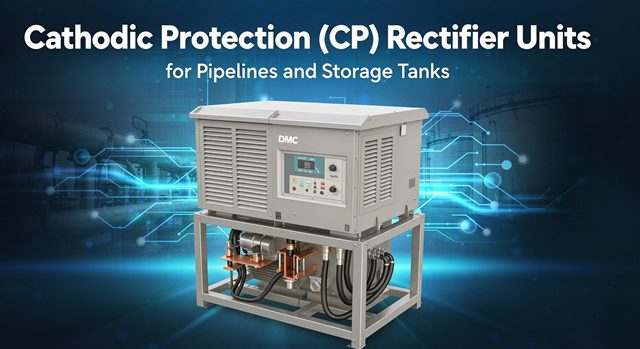
A cathodic protection rectifier takes AC mains power and turns it into low-voltage, high-current DC. That DC flows out through an inert anode bed, through the soil or water, and into your pipeline or tank bottom, turning the whole structure into the cathode of an electrochemical cell. Steel stops losing iron. The anode corrodes instead, or, with inert anodes such as MMO-coated titanium, the anode simply passes the current.
That is the whole job. Everything else in a data sheet is about how precisely, how reliably, and how safely the unit does it.
The circuit you are actually powering
Think of the CP loop as a simple series circuit with four resistances and one counter-voltage:
- Anode-to-electrolyte resistance. How hard it is for current to leave the anode into soil or water.
- Electrolyte resistance. The soil or water path between anode and structure. This is where site resistivity dominates.
- Cable resistance. Small but not zero on long runs, and it grows with every extra junction.
- Structure-to-electrolyte resistance. The interface at the steel you are protecting.
- Back EMF. Roughly 0.5 V of polarization voltage that your supply must overcome before any useful protective current flows.
The classic sizing equation captures all of it:
Vout = Imax × (Ranode + Relectrolyte + Rcable) + Eback
Then you add margin. Standard industry practice is 25% on voltage and 25% on current, applied above the calculated end-of-life demand, not day-one demand. Coatings degrade, anodes consume, soil moisture swings with the seasons, and a rectifier that was comfortable in year one is starved in year seven.
Why the equation surprises first-time buyers
Most people expect a CP rectifier to be a high-voltage machine. It is not. Outputs of 10 to 50 V DC are normal, and tank-bottom units often sit below 12 V. The current is the interesting number. Where an electrolytic rectifier might run thousands of amps at a few volts, a CP unit pushes a few amps through thousands of ohms of earth. The transformer is there to step voltage down and current up, not the other way around.
Coating condition drives everything
The coating does almost all of the protecting. CP handles the holidays, the bare spots, the damaged field joints. That has a direct consequence for sizing: current demand tracks bare steel area, not total area.
A well-coated pipeline might need a few milliamps per square metre of exposed steel. A bare or poorly coated one needs ten times that. This is why two structures of identical size can end up with rectifiers that differ by an order of magnitude, and why any supplier who quotes you from pipe length alone is guessing.
The −850 mV criterion is a target, not a rating
Here is the single most useful thing to understand before you write a specification. The −850 mV CSE number is a measurement taken on the protected structure. It is not an output setting on the rectifier, and it is not a voltage you dial into the box.
NACE/AMPP SP0169, the standard most buyers cite for buried and submerged piping, accepts several ways to demonstrate protection. Confirm which edition and which criterion your project or regulator requires before you freeze the specification.
The criteria you will see in specifications
| Criterion | Value | How it is measured | When it gets used |
|---|---|---|---|
| −850 mV CSE, current applied | −0.85 V vs copper/copper sulfate | Pipe-to-soil reading with CP on | Most common; applicable across soil types |
| Polarized −850 mV, IR-free | −0.85 V, IR drop removed | Instant-off or coupon | Preferred where soil resistance is high |
| 100 mV polarization shift | ≥100 mV from native potential | Before-and-after potential comparison | Useful in high-resistivity soils |
| Net protective current | Net cathodic current measured | Current flow survey | Where potential readings are unreliable |
| Engineering evaluation | Case-specific | Corrosion rate data and performance | Alternative criteria with justification |
A structure with a native potential around −0.60 V that reaches −0.85 V has shifted 250 mV, comfortably past the 100 mV alternative. That is the logic behind the second criterion, and it matters when soil resistivity makes an absolute −850 mV reading hard to defend.
IR drop and the instant-off reading
When protective current is flowing, the voltage you read between the pipe and a reference electrode includes the voltage drop across the soil. That IR component makes the structure look more negative than it really is. A reading of −0.90 V with current on might correspond to a true polarized potential of −0.75 V, which fails the criterion.
The fix is the instant-off technique. Interrupt all CP current sources at once and read within a fraction of a second, before depolarization sets in. That reading strips out the IR drop and shows you the polarized potential the steel actually achieved. If you specify automatic potential control, this is exactly why the rectifier needs a permanent reference electrode input: the controller needs to see the real number, not the inflated one.
A practical warning: a rectifier can be perfectly healthy, delivering exactly its rated output, while the structure is underprotected because the survey was taken with current on. Before you blame the equipment, check how the reading was taken.
The overprotection ceiling at −1.2 V
More current is not more protection. Drive the steel more negative than roughly −1,200 mV CSE and you start evolving hydrogen at the surface. On coated pipe that means blistering and disbondment. On high-strength steel, it raises the risk of hydrogen-induced cracking. It also wastes current and eats anode material faster.
That gives you a working potential window: roughly −850 mV to −1,200 mV for standard coatings such as fusion-bonded epoxy or polyethylene. Only 350 mV wide. This is why automatic control earns its keep on long lines, it holds the structure inside a narrow band as conditions change.
Where the 100 mV shift earns its place
On high-resistivity soil, chasing an absolute −850 mV reading can demand impractical current or an oversized groundbed. The 100 mV polarization criterion is the accepted alternative in many jurisdictions. It asks a different question: did the structure move at least 100 mV from where it started? For a legacy tank bottom or a pipeline in rocky terrain, that can be the difference between a workable design and an unbuildable one.
Two assets, two rectifiers: worked examples
This is where we get to the heart of the selection problem. Same protection criterion, same −850 mV target, wildly different rectifiers. Both calculations below use the sizing equation above and the 25% margin convention. Every number is reproducible.
Example A: a 30 m storage tank bottom
Assume an older tank with a degraded lining, so we take 25% bare surface area as a conservative design basis. The AWWA-style approach for water tanks uses a minimum current density of 0.5 mA/ft² of bare area.
Step 1: work out the bare area.
- Tank bottom area: π × 15² = 707 m²
- Convert to square feet: 707 × 10.764 = 7,609 ft²
- Bare at 25%: 7,609 × 0.25 = 1,902 ft²
Step 2: work out current.
- Base current: 1,902 × 0.5 mA = 0.95 A
- Apply a distribution factor of 2 for current spreading across the bottom: 1.90 A
- Apply 25% end-of-life margin: 1.90 × 1.25 = 2.38 A design current
Step 3: work out voltage and pick the unit.
- Distributed anode bed resistance, say 2.0 Ω; back EMF 0.5 V
- Vout = 2.38 × 2.0 + 0.5 = 5.26 V
- With 25% voltage margin: 6.57 V
- Select a 10 V, 5 A unit, about 50 W of installed DC capacity
That is a small rectifier. A tank bottom is a low-voltage, moderate-current job because the anode bed is close to the steel and the path is short.
Example B: a 50 km coated transmission pipeline
Now take a 24-inch line, 50 km long, with 99% coating efficiency. Bare steel is only 1% of surface area, but the line is long and the groundbed is far away electrically.
Step 1: work out the bare area.
- Pipe surface area: π × 0.6096 m × 50,000 m = 95,756 m²
- Bare at 1%: 958 m²
Step 2: work out current.
- Design current density for buried bare steel in soil: 10 mA/m²
- Base current: 958 × 0.010 = 9.58 A
- Apply 25% end-of-life margin: 11.97 A design current
Step 3: work out voltage and pick the unit.
- Deep-well groundbed plus cable resistance, say 2.5 Ω; back EMF 0.5 V
- Vout = 11.97 × 2.5 + 0.5 = 30.4 V
- With 25% voltage margin: 38.0 V
- Select a 48 V, 20 A unit, about 960 W of installed DC capacity
Side by side
| Parameter | 30 m tank bottom | 50 km coated pipeline |
|---|---|---|
| Protection criterion | −850 mV CSE, IR-free | −850 mV CSE, IR-free |
| Total area | 707 m² (7,609 ft²) | 95,756 m² |
| Coating efficiency assumed | 75% (25% bare) | 99% (1% bare) |
| Bare area | 1,902 ft² | 958 m² |
| Current density used | 0.5 mA/ft² bare | 10 mA/m² bare |
| Design current | 2.38 A | 11.97 A |
| Circuit resistance | 2.0 Ω | 2.5 Ω |
| Calculated voltage with margin | 6.6 V | 38.0 V |
| Typical selected rating | 10 V / 5 A | 48 V / 20 A |
| Installed DC capacity | 50 W | 960 W |
Nineteen times the installed power, for the same protection target. The difference is not the criterion. It is bare area and circuit resistance. If a supplier quotes you a single catalogue number for both jobs, they have not done either calculation.
Choosing the topology
Once you know volts and amps, you choose how to make them. Four technologies show up in Western CP procurement, and each suits a different site.
| Topology | Typical efficiency | Output range | Best fit | Watch out for |
|---|---|---|---|---|
| Transformer-rectifier unit, tapped | 60–75% | 10–100 V, 5–100 A | Remote sites, field repair by a tech, budget-sensitive work | Manual adjustment, larger and heavier, lower efficiency |
| Switch-mode | 85–95% | 12–60 V, up to roughly 125 A at 12 V | Automatic potential control, tight regulation, limited cabinet space | Higher unit cost, surge sensitivity, board-level repair |
| Solar-powered | Depends on array and battery | 12–48 V, 1–20 A | No AC mains, remote rights-of-way | Battery replacement cycle, weather dependence, limited current |
| Thermoelectric generator | 3–8% | 2–12 V, 0.5–5 A | Gas-bearing pipelines with no power, very remote | Fuel supply, very low output, low efficiency |
The ripple number everyone misreads
Switch-mode suppliers like to advertise “output ripple below 200 mV.” That is an absolute value, not a percentage, and the difference matters more than most buyers realize.
- On a 10 V tank-bottom rectifier, 200 mV is 2.0% ripple.
- On a 48 V pipeline rectifier, the same 200 mV is only 0.42% ripple.
Tap-controlled transformer rectifiers typically specify ripple under 3% at full load. So whether switch-mode actually buys you cleaner DC depends on the output voltage you are comparing at. Ask for ripple as a percentage at your operating point, not a headline millivolt figure. On sensitive reference-electrode control loops, low ripple is worth paying for. On a robust tank bottom with a wide potential window, it may not be.
Frequency is another quiet difference
A single-phase bridge gives you ripple at twice the line frequency: 120 Hz on 60 Hz mains, 100 Hz on 50 Hz mains. A three-phase bridge gives six times line frequency: 360 Hz at 60 Hz, 300 Hz at 50 Hz. Higher ripple frequency is easier to filter and generally means a smaller filter and a smoother output. Above roughly 20 A, three-phase is the normal industrial choice, provided three-phase power is available at the site.
Control modes: pick the one that matches your site
| Mode | What it holds | Where it fits | Where it fails |
|---|---|---|---|
| Manual | Fixed tap or potentiometer setting | Stable conditions, low criticality, short runs | Needs a site visit whenever soil or coating changes |
| Constant current | Output current regardless of voltage | Deep-well anode beds, multi-anode circuits | Structure potential drifts as resistance changes |
| Constant voltage | Output voltage regardless of current | Simple, predictable circuits | Current sags as the groundbed ages |
| Automatic potential control (APC) | Structure-to-electrolyte potential at setpoint | Seasonal moisture swings, coating degradation, stray current | Needs a reliable permanent reference electrode |
Why APC changes the maintenance model
With manual control, the rectifier holds a setting. With APC, the rectifier holds a result. A permanent reference electrode feeds the measured structure potential back to a controller, which adjusts output to keep the reading near −0.85 V. When the soil dries out in August and resistivity climbs, the unit raises voltage on its own. When a holiday is coated over in a repair, it backs off instead of overprotecting.
APC is not automatically better. It is better when the site changes, and it is a liability when the reference electrode drifts or fails, because the controller will faithfully chase a bad signal. Specify a reference electrode with a stated stability figure and a replacement interval.
Iterative instant-off is worth asking for
Some switch-mode units can perform the instant-off measurement internally, interrupting output briefly and capturing the depolarized reading. That gives you an IR-free value without a separate survey crew. On a remote line where visits are expensive, that feature can pay for itself quickly.
Construction details that decide field life
The electrical rating gets the job done on paper. These are the details that decide whether it still works in year fifteen.
Enclosure and ingress protection
For outdoor duty, IEC 60529 IP54 is a reasonable floor: dust-protected and splash-resistant. Coastal, tropical, or desert sites push you to IP65 or better. In North American specifications you will more often see NEMA 3R, 4, or 4X. NEMA 4X with a stainless or non-metallic enclosure is the usual answer for marine or chemical exposure.
Ask specifically about cable gland sealing, door gasket material, and internal condensation management. More rectifiers die from water and condensation than from failed semiconductors.
Instrumentation to specify
A practical outdoor unit should include:
- DC ammeter and voltmeter, with shunt-based current measurement
- AC input voltmeter
- Current interrupt relay for close-interval potential surveys
- Hour-run meter
- Alarm output for loss of supply or output fault
- Reference electrode input and a displayed controlled potential on APC units
Cooling
Natural convection is simple and has no moving parts. Forced-air cooling handles higher dissipation but adds a fan that will eventually fail. Oil cooling suits harsh environments and continuous full-load duty, at the cost of weight, oil containment, and a larger footprint. For the 50 W tank unit in our example, natural convection is plenty. For the 960 W pipeline unit in a hot climate, think carefully about ambient temperature and derating.
Remote monitoring
Remote terminal units connected by RS-485 Modbus, GSM, Ethernet, or satellite can report output voltage, current, structure potential, and alarms at intervals from 15 to 60 minutes. The business case is strongest where site visits are logistically expensive, because it turns a scheduled drive into an exception response.
Note the regulatory wrinkle: in the US, remote inspection does not eliminate the physical inspection requirement. More on that next.
Compliance: what US buyers must document
If your pipeline is regulated by the US Department of Transportation, the inspection cadence is law, not a recommendation. The following comes from 49 CFR § 192.465, verified against the current eCFR text as amended through 87 FR 52269 (24 August 2022). Confirm the edition in force at the time of your purchase order.
| Requirement | Frequency | Notes |
|---|---|---|
| Pipe-to-soil potential test, § 192.465(a) | At least once each calendar year, intervals not exceeding 15 months | Determines whether protection meets § 192.463 |
| Rectifier and impressed-current source inspection, § 192.465(b)(1) | Six times each calendar year, intervals not exceeding 2.5 months | May be remote measurement or onsite |
| Physical inspection of remotely inspected rectifier, § 192.465(b)(2) | At least once each calendar year, intervals not exceeding 15 months | Requirement after 1 January 2022 |
| Reverse current switches, diodes, critical interference bonds, § 192.465(c) | Six times each calendar year, intervals not exceeding 2.5 months | Other bonds: once a year, interval not exceeding 15 months |
Two details catch people out. The interval is 2.5 months, not two months, and remote monitoring does not replace the annual physical inspection. If your supplier promises a “maintenance-free” unit, treat that as a sales phrase, not a compliance strategy.
Standards map
| Standard | Covers | Applies to |
|---|---|---|
| NACE/AMPP SP0169 | External corrosion control, protection criteria | Buried and submerged metallic piping |
| NACE SP0572 | Design, installation, operation, maintenance of deep anode groundbeds | Impressed-current groundbeds |
| API RP 651 | Cathodic protection of aboveground petroleum storage tanks | Tank bottoms |
| AWWA D104 | Rectifier and CP requirements for water storage tanks | Potable water tanks |
| NSF/ANSI 61 | Drinking water system components | Materials in contact with potable water |
| 49 CFR Parts 192 and 195 | Federal safety requirements, CP and monitoring | Regulated gas and hazardous liquid pipelines |
| IEC 60529 / NEMA 250 | Enclosure ingress protection | Outdoor and harsh-location cabinets |
| IEEE Std 80 | AC substation grounding | Earthing of CP installations |
Standards get revised. State the edition you are designing to in the purchase order rather than leaving it open.
How to specify a CP rectifier: the RFQ checklist
A supplier cannot size a unit from “pipeline, 50 km” alone. Send these seven items and you will get a quote you can actually compare.
- Structure and geometry. Pipe length and diameter, tank diameter and contents, or submerged surface area.
- Coating type and condition. Coating system, age, and the assumed bare percentage. This sets current demand.
- Environment. Soil resistivity or water resistivity, temperature range, and whether the site is coastal, desert, or tropical.
- Anode bed design. Anode material, bed configuration, and calculated anode-to-earth resistance.
- Protection criterion and setpoint. The criterion you must meet, and whether you require IR-free measurement.
- Power and site conditions. Available AC voltage and frequency, or confirmation that solar or TEG is required.
- Control, monitoring and enclosure. Manual or APC, remote monitoring protocol, and required IP or NEMA rating.
What a good supplier returns
You should get back the calculated design current, the calculated output voltage with margins shown, the selected rating in volts and amps, the ripple figure at your operating point, the control mode, the enclosure rating, and the applicable standards with edition dates. If any of those are missing, the quote is not finished.
Ask also for the rectifier output curve, not just the nameplate. A 48 V, 20 A unit that cannot deliver both at once is not a 48 V, 20 A unit in any meaningful sense.
FAQ
What does a cathodic protection rectifier do in simple terms?
It converts AC mains power into low-voltage DC and pushes that current through an anode bed into a buried or submerged steel structure, making the structure the cathode so it stops corroding. Typical outputs are 10 to 50 V DC at a few to a few dozen amps.
Is −850 mV the voltage the rectifier should output?
No. −850 mV CSE is the potential the protected steel must reach, measured against a copper/copper sulfate reference electrode. The rectifier output voltage is whatever it takes to drive enough current through the circuit to get there, often 10 V on a tank bottom and 40 V or more on a long pipeline.
Why does my pipe-to-soil reading look fine but the pipe still corrodes?
Because a current-on reading includes IR drop through the soil and reads more negative than the true polarized potential. Take an instant-off reading with all CP sources interrupted. If the IR-free value is above −850 mV, the structure is underprotected regardless of what the live meter said.
What is the difference between a transformer rectifier and a switch-mode rectifier?
A tapped transformer rectifier uses a step-down transformer plus a diode or SCR bridge, with efficiencies around 60 to 75% and field-replaceable parts. A switch-mode unit uses high-frequency switching at 20 to 100 kHz, reaching 85 to 95% efficiency, tighter regulation, and a much smaller cabinet, but with higher unit cost and board-level repair.
How much current does a cathodic protection system need?
It depends mainly on bare steel area and current density, not total area. A well-coated structure may need only a fraction of what a bare one needs. As a rough guide, buried bare steel in soil is often designed around 10 mA/m², while water tank interiors are commonly designed from 0.5 mA/ft² of bare surface.
Can you overprotect a pipeline?
Yes. Potentials more negative than about −1,200 mV CSE can cause hydrogen evolution, coating disbondment, and hydrogen embrittlement on high-strength steels. The usable window between −850 mV and −1,200 mV is only 350 mV wide, which is why automatic potential control is common on long lines.
Does a 100 mV polarization shift satisfy the requirement?
Often, yes. NACE/AMPP SP0169 recognizes a shift of at least 100 mV from the native potential as an alternative criterion, particularly useful in high-resistivity soils where an absolute −850 mV reading is difficult. Confirm it is accepted by your regulator and your corrosion engineer before relying on it.
How often must CP rectifiers be inspected in the United States?
Under 49 CFR § 192.465(b)(1), six times each calendar year with intervals not exceeding 2.5 months. Remote readings count, but § 192.465(b)(2) still requires a physical inspection at least once each calendar year for remotely inspected units.
What does “ripple below 200 mV” actually mean?
It is an absolute voltage, not a percentage. On a 10 V output it is 2.0% ripple; on a 48 V output it is 0.42%. Ask for ripple as a percentage at your operating voltage so you can compare units fairly.
When should I choose solar power for a CP rectifier?
When AC mains is unavailable or unreliable and current demand is modest, typically 1 to 20 A at 12 to 48 V. Size the array and battery for the worst-case month, not the average year, and plan for battery replacement as a scheduled maintenance item.
What is automatic potential control and do I need it?
APC is a feedback loop that adjusts rectifier output to hold the structure at a set potential using a permanent reference electrode. It is worth specifying where soil moisture, coating condition, or stray current changes through the year. It needs a stable reference electrode, or it will chase a bad reading.
What information should I send to get an accurate quote?
Send structure geometry, coating type and condition, soil or water resistivity, anode bed resistance, the required protection criterion, available AC power, and your control, monitoring and enclosure requirements. Those seven items let a supplier calculate current, voltage and margin instead of guessing.