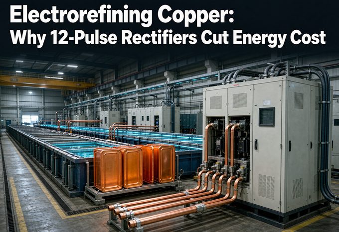
Copper electrorefining draws roughly 250 to 300 kWh of DC per tonne of cathode at only 0.2 to 0.3 V per cell, and a 12-pulse rectifier does not change that number. What it changes is the second bill: the 5th and 7th harmonics, the size of the filter, the power-factor penalty, and the heat a 6-pulse bridge pushes back into your grid.
Standards referenced: IEEE 519-2022 · IEC 61378-1 · IEC 60146 · IEEE C57.18.10 · IEC 60076
That split is the whole article. If a supplier tells you a 12-pulse rectifier cuts your energy bill by 30%, ask which bill they mean. The answer is almost never the one on your cathode production sheet.
1. Two bills hiding inside one power quote
Walk into any tankhouse and the electrical system is doing two unrelated jobs at the same time. It is pushing current through a chemical bath to move copper from one electrode to the other. And it is drawing AC from the grid in a way that either behaves itself or does not. Those two jobs produce two separate costs, and almost every brochure in this market blends them into one percentage.
1.1 The electrochemical bill
This one is set by physics you cannot negotiate with. Faraday’s law says the mass you plate depends on charge passed, not on your rectifier topology. The voltage across each cell depends on the electrolyte, the anode spacing, and the current density. A 12-pulse bridge and a 6-pulse bridge feeding the same 21 kA through the same cells will give you the same tonnes of copper and the same cell kWh.
If the tank is dirty, the anodes are passivated, or the spacing has crept out from 35 mm to 45 mm, your kWh per tonne goes up. No pulse count fixes that.
1.2 The electrical bill
This is where the rectifier architecture matters. A 6-pulse bridge draws current in six chunks per cycle and injects characteristic harmonics back into the supply. Your transformer, cables, switchgear and capacitor banks all have to carry that distortion. Depending on the short-circuit strength at your point of common coupling, you may also need a filter bank, and your utility may charge for the power factor.
A 12-pulse arrangement uses two bridges fed from secondaries displaced by 30 degrees. The 5th and 7th harmonic currents cancel at the primary. That is a grid-side effect, not a tank-side one.
The question that saves you money
Before you compare any two quotes, ask the vendor: “Is this saving measured at the DC bus or at the incoming breaker?” Those are different meters measuring different things. A supplier quoting a 36% saving at the incoming breaker with a tired thyristor stack as the baseline is not lying, but they are not answering your question either.
If your plant is a metallurgy site with several rectifier loads on one bus, solutions by industry is where we group the transformer side of that discussion, because the harmonic budget has to be shared across every DC load on the same supply.
2. The cell sets the kWh, and it is smaller than you think
2.1 Refining is not winning: 0.2 to 0.3 V
This trips up a lot of buyers, especially those coming from an electrowinning project. Copper electrowinning with an insoluble anode sits around 1.8 to 2.2 V per cell because you are splitting water at the anode. Copper electrorefining uses a soluble impure anode. Copper simply dissolves at one side and plates at the other, so there is no oxygen evolution to pay for.
The published range for a copper refining cell is 0.2 to 0.3 V. Independent process data puts the design point at 0.285 V at 320 A/m², with about 0.20 V of that being the IR drop across a 35 mm effective gap at 55 S/m electrolyte conductivity. Electrolyte typically runs 60 to 65 °C with 40 to 50 g/L Cu²⁺ and 150 to 200 g/L free H₂SO₄.
Published specific energy for copper electrorefining clusters at 250 to 300 kWh per tonne of cathode. Some sources say 200 to 300, others 250 to 350. That spread is real and it comes from anode condition, spacing and current density, not from the rectifier badge.
For comparison, copper electrowinning is commonly quoted near 2,000 kWh/t, roughly seven to ten times higher. If a quote gives you one “electrolysis rectifier” for both duties, keep looking.
2.2 The formula that closes the loop
Here is the arithmetic, and you can check every step:
m = M × I × t × η / (n × F)
With copper’s atomic mass M = 63.546 g/mol, n = 2 electrons, and F = 96,485 C/mol (26.8 Ah/mol), one ampere-hour plates 1.1855 g of copper at full efficiency. Flipped around, that is 843.5 Ah per kilogram.
Because 1 kWh/t is numerically the same as 1 Wh/kg, specific energy simplifies to:
kWh/t = V_cell × 843.5 / η
At the 0.285 V design point and 96% current efficiency, that is 250.4 kWh/t. At 0.30 V and 95%, it is 266 kWh/t. Both sit inside the published range, which is how you know the model is sound.
2.3 Where the volts actually go
The 0.285 V is not one thing. Roughly 0.20 V is electrolyte resistance. The remainder covers activation overpotential at both electrodes, contact drops at the busbars and cathode hangers, and the voltage across the rectifier’s own smoothing reactor. When someone offers to “improve rectifier efficiency” by a point, that point is available at the rectifier terminals, not inside the 0.20 V of electrolyte resistance.
The density lever
Independent cell data gives a useful rule of thumb: specific energy climbs almost linearly with current density, at about 5 kWh/t for every 10 A/m². The published pair is 249 kWh/t at 320 A/m² and 281 kWh/t at 384 A/m².
On a 100,000 t/yr line, 10 A/m² is 500,000 kWh a year. At an assumed $0.08/kWh, that is $40,000. Replace that tariff with your own before you use the number. This is a real lever, and it lives in the tank, not in the rectifier.
3. Worked example: 100,000 tonnes a year
Let me put it together so you can audit it. Assume 330 operating days a year (7,920 hours), 96% current efficiency, 0.285 V per cell, 270 A/m², and a circuit of 144 cells in series.
3.1 From tonnes to ampere-hours
100,000 t/yr is 100 million kg/yr. At 843.5 Ah/kg and 96% efficiency, that is:
100,000,000 × 843.5 / 0.96 = 87.9 billion Ah per year
Spread over 7,920 hours, the sum of circuit currents across the tankhouse is about 11.1 MA. That sounds enormous until you remember it is split into parallel circuits.
3.2 Cells, circuits and the bus
Take one circuit of 144 cells at 21,330 A and 270 A/m², a configuration that has been published by a rectifier manufacturer. Each cell plates:
144 cells is not the multiplier for mass here. Each cell carries the same 21,330 A, and at 7,920 hours each cell plates about 192 tonnes a year on its own. A 144-cell circuit makes roughly 27,685 t/yr. To reach 100,000 t/yr you need about 3.6 such circuits, or 4 circuits running a little under nameplate. Total installed cells land near 520.
The bus voltage is 144 × 0.285 V = 41.0 V at the cell terminals, before cable and contact drop. Add maybe 8 to 15 V of margin and regulation range and you are close to the 60 V / 21 kA, 1,260 kW circuit figure that appears in the manufacturer literature.
3.3 The 25 GWh power bill
At 250 kWh/t, a 100,000 t/yr refinery consumes 25 GWh of DC energy a year. Over 7,920 hours that is 3.16 MW at the DC bus. Apply a rectifier efficiency around 97% to 98% and you are drawing roughly 3.25 MVA from the AC side before harmonic allowance.
Now hold that number. It is the electrochemical bill, and the pulse count does not touch it. Everything in section 5 is about the other bill.
4. What a 6-pulse bridge does to your grid
4.1 Characteristic harmonics
A p-pulse converter generates current harmonics at h = kp ± 1, where k is any positive integer. For a 6-pulse bridge that gives the 5th, 7th, 11th, 13th, 17th, 19th and so on. Their amplitudes fall roughly as 1/h, so the 5th is about 20% of fundamental current and the 7th about 14.3%.
The ideal total harmonic distortion of a 6-pulse bridge is about 31.1%. A 12-pulse bridge is 15.2%, and 24-pulse is 7.6%. These are the classic infinite-series values. Doubling the pulse count cuts THD to about 49% of its previous value, not exactly half. Anyone who tells you 24-pulse is precisely half of 12-pulse is rounding.
4.2 The 30 degree cancellation
Two 6-pulse bridges fed from secondaries shifted by 30 electrical degrees produce 5th and 7th harmonic currents that are equal in magnitude and opposite in phase when they combine at the primary. They cancel. The first harmonic you still have to deal with is the 11th.
The general rule is a phase shift of 360°/p between adjacent bridges. So 12-pulse needs 30°, 24-pulse needs 15°, and 18-pulse needs 20°. This shift is built into the transformer windings, usually with one delta and one star secondary, or with an extended delta arrangement. You cannot get it by adding a box downstream.
Here is what changes in the harmonic spectrum, using characteristic orders up to the 49th:
| Item | 6-pulse | 12-pulse | 24-pulse |
|---|---|---|---|
| Phase shift between bridges | not applicable | 30° | 15° |
| First residual harmonic | 5th | 11th | 23rd |
| Ideal THD (infinite series) | 31.1% | 15.2% | 7.6% |
| Sum of 1/h for orders up to 50 | 0.917 | 0.349 | 0.177 |
| Measured input THDi, industry reports | around 30% | 10% to 15% | below 10% |
| Typical hardware cost vs 6-pulse | baseline | roughly +20% to +30% | higher again |
That sum-of-1/h row is a rough proxy for harmonic heating. Weighting each harmonic by its order, which is a reasonable stand-in for skin and proximity effect, the figure falls from 0.917 to 0.349. That is a 62% reduction in the heating-related weighting, even though THD itself only falls by about half. Grid heating and THD do not move in lockstep.
4.3 Ripple: two different problems
Ripple on the DC side is a separate issue from harmonics on the AC side, and people mix them up constantly.
A 6-pulse bridge at 50 Hz produces a ripple at 300 Hz. At 60 Hz it is 360 Hz. A 12-pulse bridge doubles that to 600 Hz or 720 Hz. Higher frequency means smaller filter components and less current swing between pulses.
Published numbers put unfiltered 6-pulse output at about 13% peak-to-peak ripple and 12-pulse at about 3.4%. RMS ripple figures of roughly 4.2% for 6-pulse and 1.0% to 1.2% for 12-pulse appear in electrical references. One study of 12-pulse thyristor bridges reports a ripple factor between 3.2% and 4.8% depending on load, which tells you the definition and the operating point matter. Report both when you compare.
After a reactor and filter, both topologies can meet a 1% ripple specification. The difference is what it costs to get there.
5. Where the 12-pulse money actually comes from
So if the tank kWh is unchanged, why buy 12-pulse? Four reasons, in descending order of how often they pay for the upgrade.
5.1 The filter you do not buy
A 6-pulse rectifier on a weak grid usually needs a tuned passive filter bank to bring current distortion under the utility limit. That bank is not free, and it is not lossless. Capacitor dielectric loss, reactor copper loss and the harmonic current the filter still has to absorb all show up on the meter.
Move to 12-pulse and the 5th and 7th are gone at source. The remaining filter can be smaller, or in a forgiving grid you may not need one at all. One industry estimate puts the extra saving from harmonic optimisation at about 3% of total energy, and another puts the reduction in cable and compensation cabinet losses at 5% to 9%. Treat those as directions, not guarantees. They depend entirely on your starting point.
5.2 Power factor and demand charges
A phase-controlled 6-pulse bridge running at a firing angle has a displacement power factor that falls as you turn the voltage down. Published figures put 6-pulse near 0.80 to 0.85 at full load and worse at part load. Twelve-pulse arrangements commonly land around 0.90 to 0.95, and a hybrid filter can push the input close to 0.98.
Where the utility bills for kVA demand or applies a low-power-factor surcharge, this can be the largest single line in the saving. Where the tariff only bills kWh, it may be worth nothing. You have to read your own contract.
5.3 Heating you cannot see
Harmonic current does not produce useful work, but it does produce I²R. It heats the rectifier transformer windings, the bus ducts, the switchgear and the neutral conductors upstream of the bridge. It also adds eddy loss that scales with the square of harmonic order.
This is the quiet cost. It rarely appears as a line item, but it shortens insulation life, drives the cooling fans harder, and can force a transformer derate. One estimate suggests that lower equipment temperature rise cuts annual cooling fan consumption by around 20%. That is plausible, and it is also site specific.
If your site runs several rectifiers, our industrial metallurgy power solutions note covers how we look at shared bus distortion across more than one DC load.
5.4 Cathode quality and current efficiency
Lower ripple means a steadier current density at the cathode face. Steadier current means more uniform deposition and fewer problems with nodules, roughness and short circuits. In a refining tankhouse, shorts are a direct hit on current efficiency, and current efficiency is money.
There is a limit to how far this goes. The cathode quality improvement from 12-pulse is real but usually second order compared with electrolyte cleanliness, leveler control and anode quality. Do not sell it as the main reason to buy.
A conservative saving stack
Here is how I would build an honest case on the 100 kt/yr example, with every input labelled as an assumption:
| Line | Basis | Annual effect |
|---|---|---|
| Electrochemical energy | 25 GWh at 250 kWh/t, unchanged | $0 saved by pulse count |
| Filter electrical loss avoided | assume 1% of throughput | 250 MWh, about $20,000 |
| Harmonic heating in cables and switchgear | assume 0.5% of throughput | 125 MWh, about $10,000 |
| Power factor surcharge | only if your tariff has one | site specific, possibly $0 |
| Cooling fan energy | assume 10% of auxiliary load | site specific |
| Downtime and quality | assume 0.5% better availability | 500 t of cathode, model separately |
At $0.08/kWh, the two energy lines above add up to roughly $30,000 a year against a 12-pulse hardware premium of 20% to 30%. That is a plausible, defensible case. It is nowhere near 30% of the total power bill. If you want a 30% saving, change the cell voltage, the current efficiency or the core steel, not the pulse count.
6. Three savings claims to take apart
6.1 “15 to 36% lower electricity”
This claim appears on a European modular IGBT rectifier page. The comparison is against an ageing thyristor stack, and the saving comes from a mix of higher conversion efficiency, modular redundancy and better part-load behaviour. It is not a 12-pulse versus 6-pulse comparison. If you rewrite the claim as “12-pulse saves 15 to 36%” you have changed the baseline and invented a result.
Ask for the test report. Ask what was measured, where the meters were, and what the load profile was. A number without a meter position is a marketing number.
6.2 “Grade 1 core saves 25 to 40%”
This one comes from rectifier transformer efficiency tables. It compares high-permeability silicon steel or amorphous alloy against an old Grade 3 core, often under continuous 8,760-hour duty. Amorphous claims of 60% to 70% lower no-load loss are for the core, not the whole installation.
Core material and pulse count are two independent decisions. You can buy a 6-pulse transformer with an amorphous core, or a 12-pulse transformer with ordinary silicon steel. Folding both into one percentage hides which one you are paying for.
6.3 The 1.16-year payback
A Chinese product page claims a 300 kW rectifier saves about 129,600 CNY a year with 12-pulse, for a payback of 1.16 years. The arithmetic implies an investment near 150,000 CNY, but the page does not show its electricity price, its operating hours, or whether the 5th and 7th filter was removed from the comparison.
That does not make it wrong. It makes it unusable as a bid basis. Rebuild it with your tariff, your hours and your quoted premium, and see what falls out.
7. Sizing the rectifier transformer for 12-pulse duty
7.1 kVA from DC demand
Start from the DC load, never from a catalogue kVA. The working formula is:
S = P_dc / (η_rect × kf × cosφ)
For the 3.16 MW DC example, using 97% rectifier efficiency, a 1.05 form factor and 0.95 power factor gives about 3.24 MVA before harmonic margin. A 12-pulse design with lower ripple can carry a form factor closer to 1.01 to 1.03, which trims the number slightly, but the difference is small beside the transformer’s own losses.
For a 21 kA circuit, the busbar is its own design problem. A 0.0001 Ω bus run at 21,000 A dissipates 44 kW and drops 2.1 V. That drop is bigger than a tenth of your cell voltage, which is why bus design belongs in the same conversation as rectifier selection. Our power-frequency furnace transformer page covers the low-voltage, high-current secondary construction used in this duty.
7.2 Two secondaries and one vector group
A 12-pulse transformer needs two secondary windings with a 30° displacement. Common combinations are delta and star secondaries, or a fork arrangement with two deltas. The vector group has to match the rectifier vendor’s phase sequence. A mismatch does not show up as a dramatic failure. It shows up as circulating current and a transformer that runs hot.
Confirm the phase shift in writing, then confirm it again at the factory test. Our transformer product range includes the winding arrangements used for multi-pulse converter duty, and the drawing should be part of your purchase order, not an appendix.
7.3 Impedance, OLTC and cooling
Short-circuit impedance controls commutation overlap, the DC voltage drop under load, and how much fault current the thyristors have to survive. Published guidance puts 4% to 6% in the light-duty range and 6% to 10% for standard electrolysis and heavy rectifier duty. Too low and a commutation fault destroys the stack. Too high and you lose regulation and add loss.
An OLTC is worth considering where the grid voltage moves or where you want to hold a firing angle near its efficient range. Cooling is a real choice: oil immersed for outdoor, high overload capacity and MVA scale; cast resin dry type for indoor installations where fire safety and low maintenance matter more. Our notes on IEC versus ANSI/IEEE standards for export units explain how the two standards stacks treat these same parameters differently.
7.4 What to send in an RFQ
Put these on one page before you ask for a price:
- Annual cathode tonnage and operating hours per year
- Number of cells per circuit and cells in total
- Design current density in A/m² and the resulting circuit current in kA
- Cell voltage at that density, with the source of the figure
- Required DC voltage range and current efficiency assumption
- Measured or assumed ripple limit at the DC bus
- Isc/IL at the point of common coupling, and the utility’s harmonic contract
- Cooling medium, installation location and ambient range
- Whether the quote includes the 5th and 7th filter, and where it sits
- Required standards edition and test witness points
Item 7 is the one most buyers forget, and it decides more hardware than item 4.
8. Compliance: IEEE 519 at the PCC
8.1 TDD, not THD
IEEE 519 limits current distortion at the point of common coupling, using total demand distortion with the maximum demand load current as the denominator. It does not measure THD at the transformer nameplate, and it does not measure anything at your DC bus.
The current distortion table has five bands based on the ratio of short-circuit current to load current at the PCC:
| Isc/IL at PCC | TDD limit |
|---|---|
| less than 20 | 5.0% |
| 20 to 50 | 8.0% |
| 50 to 100 | 12.0% |
| 100 to 1,000 | 15.0% |
| above 1,000 | 20.0% |
Read that table next to the 15.2% ideal THD of a 12-pulse bridge. On a stiff grid above 1,000, a filtered 12-pulse has room. On a weak grid below 20, where the limit is 5% TDD, 12-pulse on its own has no chance. The utility decides your topology, not the rectifier catalogue.
8.2 Why 12-pulse alone can still fail
There is a widespread belief that specifying 12-pulse closes the compliance question. Published work on multi-pulse thyristor converters does not support that. A study of 12-pulse bridges for electrolysers concludes that a hybrid filter combining a shunt passive filter with a STATCOM is still needed to meet IEEE 519, reaching 0.98 input power factor and 4.8% THD with that filter in place.
That result is from a hydrogen electrolyser, not a copper tankhouse, but the bridge physics is the same. Budget for the filter until your grid study says otherwise.
8.3 The IEC side of the file
For a project outside North America, IEC 61378-1 is the converter transformer standard and IEC 60146 covers the semiconductor converters. IEEE C57.18.10 applies to rectifier transformers in the IEEE stack. These documents divide the same equipment differently, and the test requirements are not interchangeable.
Confirm the current edition of each before you write a guaranteed loss figure or a harmonic limit into a contract. We have seen bids fail because the loss guarantee was written to one standard and the factory test was run to another.
9. Seven mistakes that cost real money
- Specifying voltage without cell count. A 60 V bus means nothing until you know how many cells are in series and what each one drops.
- Buying on kW and ignoring kA. At 21 kA, bus resistance is a design driver. A tenth of a milliohm is a meaningful voltage drop.
- Treating THD and TDD as the same number. One is measured at your transformer, the other at the PCC against maximum demand current.
- Assuming 12-pulse passes IEEE 519. On a weak grid it will not, and the filter still belongs in the quote.
- Comparing savings across different baselines. IGBT against old SCR, amorphous core against Grade 3 steel, and 12-pulse against 6-pulse are three different claims.
- Forgetting the anode. Cell voltage improves with clean electrolyte, close spacing and healthy anodes. No rectifier upgrade compensates for a dirty tank.
- Skipping the electrolyte testwork. The 0.285 V design point is a starting figure. Your bath sets the real one, and every 10 A/m² is about 5 kWh/t.
More worked examples and sizing notes sit in the technical resources library, where we keep the calculation sheets alongside the articles.
FAQ
How much electricity does copper electrorefining use?
Published figures cluster at 250 to 300 kWh of DC per tonne of cathode, with some sources quoting 200 to 300 and others 250 to 350. At 0.285 V per cell and 96% current efficiency, the formula V_cell × 843.5 / efficiency gives 250.4 kWh/t. Copper electrowinning is far higher, commonly near 2,000 kWh/t.
Why is electrorefining voltage so much lower than electrowinning?
Electrorefining uses a soluble impure anode, so copper dissolves at one side and plates at the other without evolving oxygen. That puts the cell at 0.2 to 0.3 V. Electrowinning uses an insoluble anode and has to split water, which pushes the cell to 1.8 to 2.2 V for copper.
Does a 12-pulse rectifier reduce kWh per tonne of cathode?
Not directly. Faraday’s law sets the mass from charge passed, and cell voltage sets the electrochemical energy. Twelve-pulse changes the AC side: it cancels the 5th and 7th harmonics, lowers input THD from about 31% to 15%, reduces ripple, and can cut filter and power factor costs. Real total energy savings are usually a few percent, not 15% to 36%.
What harmonics does a 6-pulse rectifier produce?
Characteristic harmonics occur at h = kp ± 1. For a 6-pulse bridge that is the 5th, 7th, 11th, 13th, 17th, 19th and so on, with amplitudes falling roughly as 1/h. Ideal THD is about 31.1%. A 12-pulse bridge at a 30 degree phase shift cancels the 5th and 7th and starts at the 11th.
How much does the phase shift need to be for 12-pulse?
Thirty electrical degrees between the two 6-pulse bridges. The general rule is 360°/p, so 12-pulse is 30°, 18-pulse is 20°, and 24-pulse is 15°. The shift is built into the transformer secondaries, usually with delta and star windings or an extended delta.
What is the difference between ripple and harmonics here?
Harmonics are on the AC side and describe distortion in the current drawn from the grid. Ripple is on the DC side and describes the remaining AC component in the output. A 6-pulse bridge at 60 Hz gives 360 Hz ripple at roughly 13% peak-to-peak. A 12-pulse bridge gives 720 Hz at about 3.4%. After filtering, both can meet a 1% ripple limit.
Will 12-pulse pass IEEE 519 without a filter?
It depends on the short-circuit ratio at the point of common coupling. IEEE 519 sets a 5% TDD limit when Isc/IL is below 20, and 20% when it is above 1,000. A 12-pulse bridge has about 15.2% ideal THD, so on a weak grid it still needs filtering. Published converter studies recommend a hybrid filter even with 12-pulse.
How do I size a rectifier transformer for copper electrorefining?
Use S = P_dc / (η_rect × kf × cosφ), starting from DC voltage and current. For a 3.16 MW DC load at 97% efficiency, 1.05 form factor and 0.95 power factor, that is about 3.24 MVA before harmonic margin. Then check the secondary arrangement for the required phase shift, the impedance for commutation duty, and the cooling method for the site.
Why do suppliers quote 15% to 36% energy savings?
Those figures usually compare a modern modular IGBT rectifier against an old thyristor stack, or a Grade 1 core against a Grade 3 core. Neither is a 12-pulse versus 6-pulse comparison. Ask which baseline was used and where the meters were installed before you put the number in a business case.
What information do you need to quote a rectifier transformer for an electrorefining line?
Send annual cathode tonnage, operating hours, cells per circuit, circuit current in kA, cell voltage at design current density, DC voltage range, ripple limit, Isc/IL at the PCC, the utility harmonic contract, cooling preference, installation location, and the standards edition you need. The short-circuit ratio and the ripple limit decide more hardware than most buyers expect.