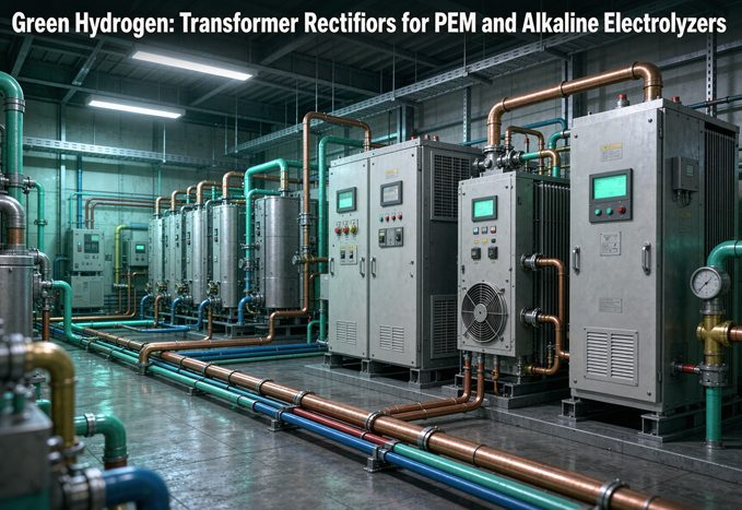
PEM and alkaline electrolyzers need the same basic transformer rectifier but not the same electrical spec: alkaline stacks run about 1.8–2.2 V per cell at 0.2–0.8 A/cm² and accept ripple near 8%, while PEM runs at higher current density with tighter ripple under 5% and a response in tens of milliseconds, and the number most buyers get wrong is the end-of-life stack voltage, because you must size the rectifier voltage window for a degraded stack at full load, not the day-one value.
That difference sounds small on a datasheet. On a 10 MW project it changes the valve-side winding voltage by a factor of two, doubles the DC bus current, and decides whether your stack lasts 40,000 hours or half of that. This guide walks the whole chain, from a single cell to the transformer nameplate, and ends with a checklist you can send to a supplier today.
Last updated 18 November 2026. Written for EPCs, electrolyzer OEMs and power-system buyers specifying AC/DC conversion for water electrolysis.
1. The power chain: from the grid to the stack
What a hydrogen rectifier transformer actually does
A transformer rectifier for electrolysis is two pieces of equipment treated as one system. The transformer steps medium-voltage grid or renewable collection power, usually 13.8 kV to 34.5 kV in North America and 10 kV to 35 kV elsewhere, down to a low-voltage, high-current AC feed. The rectifier, built with thyristors (SCR) or IGBTs, turns that AC into DC on the electrolyzer bus.
Four jobs sit on the transformer side:
- Galvanic isolation between the grid and the stack
- Voltage transformation into the window the stack needs across its whole life
- Phase shifting of multiple secondary windings so harmonics cancel in the primary
- Commutation impedance that limits fault current into the semiconductor bridges
You can see the equipment families we build in our transformer product range, and the application framing in application-specific solutions.
Why a standard distribution transformer fails here
A distribution transformer is designed around a sinusoidal linear load. An electrolyzer is the opposite: a non-linear, high-current load that pulls current in short pulses and draws the transformer into continuous partial-load and overload cycling.
Harmonic heating is not theoretical
Winding eddy loss scales with the square of harmonic order times the square of harmonic current, roughly `P_EC ∝ I² × f²`. In a 6-pulse bridge the 5th and 7th harmonics dominate. A winding that survives a sinusoidal current at the same RMS value can run hot enough to degrade insulation early when those harmonics are present. Standards such as IEC 61378-1 and IEEE C57.18.10 exist precisely because the usual sinusoidal loss assumptions do not hold.
Stray flux and the low-voltage bus
At 10,000 A to 40,000 A, leakage flux in tank walls, clamps and tie plates becomes a real heat source, and the busbar itself is a measurable voltage drop. On a 10 MW alkaline train at 10,000 A, a bus path of 100 micro-ohms drops 1 V and dissipates 10 kW. Double the current to 20,000 A and the same bus drops 2 V and burns 40 kW. That is why electrolyzer rectifiers are normally installed close to the stacks.
Typical numbers you will see in a datasheet
| Item | Common range | Note |
|---|---|---|
| Grid side voltage | 13.8–34.5 kV (NA), 10–35 kV (IEC) | 110 kV for very large plants |
| DC bus voltage | 200–1,000 V, up to 1,500 V | EU low-voltage directive ceiling is 1,500 V DC |
| DC current | 5–40 kA per train | Parallel bridges above that |
| Unit rating | 3–12 MVA industrial, 20–60 MVA wind/solar | 16 units on some large projects |
| Pulse configuration | 12, 24, 48, occasionally 96 | Sets harmonics and ripple |
| Short-circuit impedance | 6–10% standard for electrolysis | Lower risks SCR damage, higher hurts regulation |
| Full-load efficiency | 97.5% or better (transformer) | Rectifier efficiency is a separate number |
| Ripple at DC terminals | PEM <5%, alkaline <8% | Confirm against stack OEM datasheet |
2. PEM vs alkaline: what actually changes at the DC terminals
Cell voltage and current density are not the headline
Both technologies split water at roughly 1.8–2.2 V per cell in normal operation. Where they differ is how much current you can push through a square centimetre of active area, and how fast you can change it.
| Parameter (DOE technical targets, status values) | PEM 2022 status | PEM 2026 target | Alkaline 2022 status | Alkaline 2026 target |
|---|---|---|---|---|
| Rated performance | 2.0 A/cm² @ 1.9 V | 3.0 A/cm² @ 1.8 V | 0.5 A/cm² @ 1.9 V | 1.0 A/cm² @ 1.8 V |
| Average degradation rate | 4.8 mV/kh | 2.3 mV/kh | 3.2 mV/kh | 2.3 mV/kh |
| Stack lifetime | 40,000 h | 80,000 h | 60,000 h | 80,000 h |
These are targets, not guarantees. Lifetime is usually defined as the point where cell voltage has risen 10% from its initial value at the same current density. Note the practical consequence: at 1.9 V, PEM delivers about 2.0 A/cm² while alkaline delivers about 0.5 A/cm², so the electrode area needed for the same current is roughly four times larger for alkaline. That is why PEM stacks are compact, and why they cost more per kilowatt.
A caveat worth stating plainly: some supplier pages claim PEM is inherently more efficient because it runs at lower cell voltage. At realistic current densities both technologies land near 1.9–2.0 V, so the efficiency gap in a real plant is usually small. Treat a large claimed gap as a question for the stack OEM, not a fact.
Ripple: the number that quietly eats stack life
Ripple is the AC component left on top of the DC output. It does not make hydrogen. It becomes heat, catalyst stress and membrane fatigue.
| Specification item | Alkaline | PEM |
|---|---|---|
| Accepted DC ripple (industry guidance) | <8%, best practice <3% | <5%, best practice <3% |
| Ripple sensitivity | 0.8–1.2 mV/cm² per 1% ripple | 2.5–3.8 mV/cm² per 1% ripple |
| Lifetime reduction per 1% ripple | 1.5–2.0% | 3.5–5.0% |
| Dominant frequency band | Low frequency, 100–300 Hz | High frequency, above 1 kHz |
| Main degradation path | Diaphragm mechanical stress | Membrane chemical and mechanical fatigue |
The numbers above are published vendor guidance, not a universal standard, so confirm the exact limit with your stack OEM. The mechanism is nevertheless consistent across sources: high-frequency ripple drives local potential swings across the catalyst layer, accelerates iridium dissolution on a PEM anode and promotes peroxide formation that attacks the membrane. In alkaline cells the diaphragm takes the mechanical cycling instead. If you are following a mixed project, the PEM rectifier gets the tighter filter; sharing one ripple spec across both stacks is a common and expensive mistake.
Response time: a fast stack with a slow rectifier is a slow plant
PEM recovers from a load transient in roughly 20–100 ms. Alkaline typically takes 500–2,000 ms. PEM is therefore the natural choice for following solar and wind directly, but only if the power supply can keep up. A thyristor bridge with a slow current loop and a conservative filter will flatten the response of an otherwise fast stack, and you end up paying PEM prices for alkaline-like production flexibility.
For a renewable-coupled project, ask for the closed-loop step response at the DC terminals, not the semiconductor switching speed. Those are very different numbers. If the stack is fast and the rectifier is slow, the bottleneck is your purchase order.
Two specs that get mixed up: DC ripple and AC-side THD
This is the most common source of confusion in this topic. They are measured in different places and are not interchangeable.
- DC ripple percentage is the residual AC on the electrolyzer bus, usually expressed against the DC average. This is what the stack feels. Target under 5% for PEM.
- AC-side current THD or TDD is the distortion the rectifier draws from the medium-voltage network, measured at the point of common coupling. This is what the utility cares about, under IEEE 519-2022 or your local grid code.
A 96-pulse transformer advertised as “THD below 10%” is talking about the AC side. It says nothing by itself about ripple at the stack. Conversely, a tight DC filter does not guarantee grid compliance. Ask for both numbers, both test points and both operating loads.
3. Pulse number and harmonics: 6, 12, 24, 48
The phase-shift rule behind every multi-pulse transformer
A six-pulse bridge produces characteristic harmonics at `h = k × p ± 1`, so for p = 6 you get the 5th, 7th, 11th and 13th, with ideal amplitudes near `I₁ / h`. Feed two bridges from secondaries shifted 30° apart and the 5th and 7th currents cancel in the primary. Four secondaries at 15° relative shift move the first remaining harmonic to the 23rd.
The general phase step is `360° / p`, which is 60° per bridge for a 6-pulse system, 30° for 12-pulse, 20° for 18-pulse, 15° for 24-pulse and 10° for 36-pulse. The shift is built into the winding arrangement, usually a star/delta pair or an extended-delta and zigzag winding. It is not something the rectifier control can create after the fact. Vector groups have to be agreed between transformer and rectifier suppliers before production.
Ideal THD by pulse number
| Pulse number | Secondaries and phase step | First remaining harmonics | Ideal current THD |
|---|---|---|---|
| 6 | 1, no shift | 5, 7, 11, 13 | 31.08% |
| 12 | 2 at 30° | 11, 13, 23, 25 | 15.22% |
| 18 | 3 at 20° | 17, 19, 35, 37 | 10.11% |
| 24 | 4 at 15° | 23, 25, 47, 49 | 7.57% |
| 36 | 6 at 10° | 35, 37 | 5.04% |
| 48 | 8 at 7.5° | 47, 49 | 3.78% |
These are ideal values from the classic characteristic-harmonic model. Real measurements are higher because of firing-angle imbalance, transformer impedance mismatch and background grid distortion. Published IEEE work notes a conventional 12-pulse diode rectifier around 15% THD, above IEEE 519 limits, which is why 24-pulse and passive or active filters remain common on sensitive connections.
Why 24-pulse is a shortcut, not a law
You will read that 12-pulse suits alkaline and 24-pulse suits PEM. That is a useful starting point, not a specification. What actually sets pulse number is the grid code at your point of connection and the ripple tolerance at your stack. A weak grid with a low short-circuit ratio may need 24-pulse even for alkaline. A strong industrial grid with a generous harmonic allocation may let a well-filtered 12-pulse PEM train comply.
The IEEE 519 test point is the PCC
IEEE 519-2022 limits apply at the point of common coupling, not at the transformer terminals and not on a rectifier nameplate. The allowed TDD depends on the ratio of short-circuit current to load current at that point, from 5% for the strictest band below 20, up to 20% for ratios above 1,000. Get that ratio from the utility before you lock the topology. Choosing pulse number without it is guesswork.
For background on how these winding arrangements are specified in practice, see our technical resources library. Examples of comparable converter-duty units are documented among delivered projects.
4. Sizing worked example: 10 MW, two electrolyzer choices
Here is the chain you can reproduce. We compare two 10 MW DC trains, one alkaline and one PEM, using vendor-typical stack architectures. These are illustrative figures, not a substitute for the stack OEM data sheet.
Step 1: fix the DC operating window
| Train | DC power | Stack voltage | DC current | Architecture |
|---|---|---|---|---|
| Alkaline | 10 MW | 1,000 V | 10,000 A | 12-pulse, two bridges at 5,000 A |
| PEM | 10 MW | 500 V | 20,000 A | 24-pulse, four bridges at 5,000 A |
The PEM train uses half the stack voltage and twice the current because PEM delivers more current per unit of electrode area. Published vendor examples show the same pattern: a 1 MW PEM skid around 500 V and 2,000 A, a 10 MW alkaline skid around 1,000 V and 10,000 A.
Step 2: turn DC into valve-side AC
For a three-phase bridge, the ideal no-load DC voltage is `Udi0 = 1.35 × Uv0`, where `Uv0` is the valve-side line-to-line RMS voltage. Thyristor control and commutation reduce the delivered voltage:
`Ud = Udi0 × cos α − Udx − UT`
At rated current the commutation drop is approximately `Udx = (ux / 2) × Udi0`. With a short-circuit impedance `ux` of 8%, the voltage ratio `Ud / Udi0` is about 0.96, ignoring device drops. So:
- Alkaline: `Udi0 = 1,000 / 0.96 = 1,042 V`, so `Uv0 = 1,042 / 1.35 = 772 V` line to line per secondary
- PEM: `Udi0 = 500 / 0.96 = 521 V`, so `Uv0 = 521 / 1.35 = 386 V` line to line per secondary
Valve winding RMS current per bridge is about `Iv = 0.816 × Id`, giving 4,080 A per secondary in both trains because each bridge carries 5,000 A.
Transformer rating per secondary is `S = √3 × Uv0 × Iv`, and the cross-check is `S ≈ 1.047 × Udi0 × Id` per bridge:
| Train | Secondary voltage | Bridges | MVA per secondary | Total transformer MVA |
|---|---|---|---|---|
| Alkaline 12-pulse | 772 V | 2 | 5.45 | 10.9 |
| PEM 24-pulse | 386 V | 4 | 2.73 | 10.9 |
This is the result most buyers find counterintuitive. The transformer MVA is essentially the same, because MVA follows power, not electrolyzer type. What changes is the valve-side voltage, the number of secondaries and the current in the DC bus. A supplier who quotes radically different MVA for two 10 MW stacks is probably sizing one of them wrong.
Step 3: check the busbar before you sign
At 100 micro-ohms of bus path, the alkaline train drops 1 V and loses 10 kW. The PEM train drops 2 V and loses 40 kW. As a share of stack voltage that is 0.1% versus 0.4%, which matters when your cell voltage is only 1.9 V. Specify bus cross-section, joint treatment and rectifier-to-stack distance in the same conversation as the transformer.
Add the usual margins after this calculation: device forward drops, bus losses, tap range for process control and the voltage rise of an ageing stack. On this example a 10.9 MVA core calculation normally becomes a 12–13 MVA order before project margin.
5. The end-of-life voltage window trap
What degradation actually does
Electrolyzer cells do not stay at their day-one voltage. DOE data puts average degradation at 4.8 mV per 1,000 hours for PEM and 3.2 mV/kh for alkaline in current status machines, with lifetime defined at a 10% voltage rise. Some PEM design guidance puts the end-of-life ceiling near 2.4 V per cell.
A 10% rise on a 1,000 V alkaline stack means 1,100 V. On a 500 V PEM stack it means 550 V. If the rectifier cannot reach that upper value at full current, the plant cannot make its rated hydrogen at the end of life, even though every other component is healthy.
How much headroom to specify
The rectifier output window must cover two extremes:
- Minimum stack voltage at start of life and partial load
- Maximum stack voltage at end of life and full load
Thyristor rectifiers have no practical minimum DC voltage limit, which is one reason they remain common on large stacks. IGBT platforms offer faster control and better part-load efficiency, with published figures around 94% and 96% for newer silicon-carbide designs, but the top of the voltage window still has to be designed in.
If your stack starts at 1,000 V and ends at 1,100 V, size the transformer valve side for 1,100 V at full current. Recalculating the example above at 1,100 V raises the required transformer to about 12 MVA before project margin, roughly 10% above the day-one figure. That is the difference between a plant that holds output in year ten and one that quietly derates.
Turndown is a stack limit, not a rectifier limit
PEM stacks are often said to run from 0% to 100% load. In practice hydrogen crossover in the membrane sets a floor around 15–20% load, because the gas mixture becomes unsafe below that. Alkaline units are generally more limited in dynamic response but can sit comfortably at steady load for decades. Ask for the real turndown envelope from the stack OEM and confirm the rectifier can hold current stably at the bottom of it. Do not specify a 10% turndown on a rectifier feeding a stack that cannot safely operate there.
6. Specification and standards checklist
What belongs on the single-line diagram
Before anyone quotes, fix these items. Leaving any one of them open produces a price that cannot be honoured.
- Grid voltage, frequency, short-circuit level and earthing arrangement
- HV connection and tap range, including whether OLTC is required
- Electrolyzer type, rated DC voltage window, rated DC current and overload duty
- Ripple limit at the stack terminals and the measurement bandwidth
- Pulse number, secondary winding count and vector group
- Closed-loop response time and the interface to the plant EMS
- Cooling medium, ambient temperature, altitude and enclosure rating
- Communications protocol and the points to be mapped into the DCS
The winding and cooling choices interact. Oil-immersed units handle MVA-scale overload and outdoor duty better, while cast-resin units suit indoor installations with stricter fire requirements. Our special transformers note covers the construction variants used on converter duty, and the renewable-energy transformer solutions page describes the collector-side arrangements used with wind and solar.
Standards to name in the tender
| Standard | Covers | How to cite it |
|---|---|---|
| IEC 61378-1 | Converter transformers for industrial applications | Confirm current edition before tender |
| IEEE C57.18.10 | Semiconductor rectifier transformers | Confirm current edition before tender |
| IEEE 519-2022 | Harmonic limits at the point of common coupling | State the Isc/IL ratio used |
| IEC 61000-3-6 | Grid harmonic emission for medium-voltage systems | Confirm local adoption |
| IEC 60076 series | Power transformer fundamentals and testing | Reference alongside converter standard |
| IEC 60214-1 | On-load tap changers | Only if OLTC specified |
| IEC 60079 / ATEX / NEC 500 | Hazardous area equipment and classification | Confirm zone or division with site engineer |
Do not write a year or clause number you have not checked against the current revision. A wrong standard reference in a tender is worse than no reference, because it gives the buyer something concrete to challenge.
Hazardous area: do not guess the classification
Hydrogen is a wide-range, easily ignited gas, and electrolyzer rooms are normally classified. The enclosure, ventilation, cable glands and instrumentation have to follow the classification agreed for that specific site. IEC 60079, ATEX and NEC Article 500 use different frameworks, so the same equipment is not automatically acceptable in Europe and North America. Get the area classification drawing from the EPC before selecting enclosures, and record it in the RFQ.
7. RFQ checklist: what to send before you ask for a price
A useful enquiry is two pages of data, not one line asking for “a rectifier transformer for a green hydrogen plant.” Copy this into your next request.
| Electrolyzer side | Grid and site side |
|---|---|
| Technology: PEM, alkaline or mixed | Grid voltage and frequency |
| Rated DC power in MW | Short-circuit level at the PCC |
| DC voltage window, start and end of life | Harmonic limit and Isc/IL ratio |
| Rated and overload DC current | HV connection and tap requirements |
| Ripple limit and measurement bandwidth | Indoor or outdoor, ambient range |
| Load profile and ramp rate | Altitude, pollution and corrosion level |
| Stack OEM and interface requirement | Hazardous area classification |
| Expansion plan in MW | Required standards and inspection regime |
Three questions that expose a weak quotation
- “What valve-side voltage did you use, and what DC voltage does it produce at rated current after commutation drop?” If the answer equates AC secondary voltage with DC voltage, the sizing is not finished.
- “Where is the ripple measured, and at what load?” A single ripple figure without a test point and bandwidth is not verifiable.
- “What happens to the output at end-of-life stack voltage?” If the supplier has not modelled the 10% voltage rise, the plant will derate.
FAQ
What voltage and current does a typical green hydrogen rectifier deliver?
A 10 MW alkaline train is commonly around 1,000 V DC and 10,000 A, while a 10 MW PEM train is often around 500 V and 20,000 A because PEM supports higher current density. Stack voltage at cell level is about 1.8–2.2 V, multiplied by the number of cells in series. Confirm the exact window with the stack OEM.
Can one transformer rectifier serve both PEM and alkaline electrolyzers?
The same 0–700 V adjustable platform can be configured for both, but ripple, response and control settings must be re-checked against each stack datasheet. In a mixed project, alkaline usually takes base load and PEM follows renewables, so the two rectifiers are specified differently even if the hardware looks similar.
What ripple level is acceptable for a PEM electrolyzer?
Industry guidance typically recommends DC ripple below 5%, with best practice targeting 3% or lower. Confirm the exact limit with the stack OEM, and specify the measurement bandwidth, because high-frequency components above 1 kHz drive membrane fatigue.
What ripple level is acceptable for an alkaline electrolyzer?
Alkaline stacks generally tolerate up to about 8% DC ripple, though 3% or lower is often targeted to reduce diaphragm stress and extend life. This is a DC terminal specification, not the AC-side THD at the grid connection.
Why does PEM need faster dynamic response than alkaline?
PEM stacks are used to absorb variable solar and wind output and can recover from a transient in roughly 20–100 ms, compared with 500–2,000 ms for alkaline. If the rectifier current loop is slower than the stack, the plant cannot capture the available renewable energy.
How do I size the transformer kVA for an electrolyzer?
Start from DC power, not AC nameplate. Divide the ideal no-load DC voltage by 1.35 to get valve-side line-to-line voltage, apply `Iv = 0.816 × Id` per bridge, then `S = √3 × Uv0 × Iv`. For a 10 MW train at 1,000 V and 12-pulse, the result is about 10.9 MVA before device drops, bus losses and end-of-life voltage headroom.
Why is the transformer MVA the same for PEM and alkaline at the same power?
MVA follows power. A 10 MW alkaline train at 1,000 V and 10 kA and a 10 MW PEM train at 500 V and 20 kA both need roughly 10.9 MVA. What changes is the valve-side voltage, the number of secondaries and the DC bus current, which quadruples bus I²R loss when current doubles.
What pulse number should I specify?
It depends on the grid code at the point of common coupling and the stack ripple limit. Twelve-pulse cancels the 5th and 7th harmonics and suits many alkaline plants. Twenty-four-pulse reduces ideal current THD to about 7.6% and is common for PEM and weak grids. Confirm the utility’s Isc/IL ratio before deciding.
Does a higher pulse number always mean lower DC ripple?
Not by itself. Pulse number mainly reduces low-order harmonics drawn from the grid. Ripple at the stack also depends on the DC filter, switching frequency and control strategy. Ask for both the AC-side TDD at the PCC and the DC ripple at the electrolyzer terminals.
How much voltage headroom does an ageing stack need?
DOE defines stack life at a 10% voltage rise from the initial value at the same current density. A 1,000 V stack can therefore need 1,100 V at full current at end of life. Size the rectifier voltage window and transformer valve side for that upper value, not the day-one figure.
What standards should a hydrogen rectifier transformer meet?
Name IEC 61378-1 for converter transformers, IEEE C57.18.10 for semiconductor rectifier transformers, IEEE 519-2022 for grid harmonics and IEC 61000-3-6 for medium-voltage emission, plus the IEC 60076 series. Confirm the current revision of each before issuing the tender.
What should I prepare before requesting a quote?
Prepare electrolyzer type, DC voltage window, rated and overload current, ripple limit, ramp rate, grid voltage and short-circuit level, harmonic limit, cooling and site conditions, hazardous area classification and the expansion plan. Send these to talk to our engineering team and we will run the numbers.