Pulse number is not a harmonic limit. An ideal 6 pulse bridge draws 31.08 percent current THD, a 12 pulse bank 15.22 percent and a 24 pulse bank 7.57 percent, all from one over h. IEEE 519-2022 caps the whole site at the point of common coupling, not the transformer. Name the denominator, the short circuit ratio and the measurement point before comparing quotes.
If you came here from another page on our site, here is where this one sits. Our page on rectifier transformers already explains what the unit is, where it goes in a DC drive, an electrolysis line or a traction substation, and how IEC 61378-1 and IEEE C57.18.10 divide the testing work. Our data center page covers K factor, harmonic derating and the short circuit ratio at the service entrance. Those questions are settled and we are not going to answer them again. This page does a different job. It takes three pulse numbers, works out the current spectrum each one produces from a single formula, puts that spectrum cell by cell against IEEE 519-2022 Table 2, and then asks where the harmonic current that gets cancelled on the primary actually went. No price list, no vendor ranking, no sizing example. If you are writing a specification, this is the page that tells you what the pulse number does and does not promise.
The short answer, before the table
Here is the six row shape a search engine likes to lift, with every cell holding a number you can recompute. Run it across your own submittal before the RFQ goes out.
| If your question is | What actually answers it | Number to check | What goes in the spec |
|---|---|---|---|
| How much distortion does each design make | The ideal one over h spectrum, summed in closed form | 31.08, 15.22 and 7.57 percent for 6, 12 and 24 pulse | The pulse count plus the assumed load and firing angle |
| Which harmonics survive | h equals k times p plus or minus 1 | First surviving order 5, 11 and 23 | A harmonic spectrum, not a single THD figure |
| How far apart are the bridges | 360 degrees divided by the pulse count | 60, 30 and 15 degrees | The winding phase shift and the vector group |
| Does that meet the code | IEEE 519-2022 Table 2 at the PCC, not the nameplate | 11th at 4.55 times and 23rd at 7.25 times the tightest row | Isc/IL, IL and the measurement window |
| What does the cancellation cost | Winding eddy loss under the actual spectrum | 17, 9 and 5 weighted terms at h up to 50 | A harmonic loss factor, not a sine wave guarantee |
| What proves any of it | A harmonic study and a measured spectrum at the PCC | Six published THD values spanning 6 to 15 percent at 12 pulse | Report number, load point, test method, denominator |
Read down the second column. Not one row says cleaner, premium, low distortion or heavy duty. Each row gives you a formula, a harmonic order, an angle or a table reference. That is the point. Most of the pages we looked at print a three column comparison with adjectives in the cells, and adjectives are exactly what disappear when a reviewer asks for the study.
Six rows instead of three definitions
The comparison table is not the problem. Buyers scan a table in ten seconds and the ranking pages are right to put one near the top. The problem is what sits inside the cells. One vendor page runs a four row table of pulse number, THD, cost and recommended application, then fills the last column with precision equipment, large industrial drives and green energy. Those are not limits. They are sales copy, and a reviewer cannot check any of them against a test report.
Keep the shape and change the contents. Every row above is one question answered by one number you can recompute on a single line. If a quotation cannot fill the fourth column, the harmonic discussion is not finished. Ask again, and ask which edition of the standard the number belongs to.
What the ranking pages get right
Give the search results their due, because several of them are genuinely useful.
A university thesis on 12 pulse rectifiers writes out the line current Fourier series in full. It shows the 5th and 7th terms disappearing, keeps the 11th and 13th with their signs, and explains that the 12k plus 1 orders are positive sequence while the 12k minus 1 orders are negative sequence. It also says in plain language that pushing distortion below 4.5 percent rarely pays for the extra hardware, and it lists the reliability cost of adding devices. That is an academic source doing engineering, and we give it full credit.
A power electronics course page and a conference paper both carry the 6 pulse derivation all the way to a number. They give Is as the square root of two thirds times Id, which is 0.8165 Id, and the fundamental Is1 as the square root of six over pi times Id, which is 0.7797 Id. The distortion factor comes out as three over pi, or 0.9549, and the THD is the square root of one over that squared minus one. That is 31.08 percent, and it is the same number we get from a completely different route later in this article. Two independent derivations, one answer.
A manufacturer’s rectifier guide gives a worked electrolysis example at 12 MW, 600 V and 20 kA, with Udi0 at 1.35 times the secondary voltage and the transformer rating near 1.05 times Udi0 times Id. It then says the winding eddy loss rises with the square of the harmonic order times the square of the harmonic current, and that IEC 61378-1 and IEEE C57.18.10 expect losses to be computed from the harmonic spectrum rather than from a sine wave assumption. That last sentence is the kind of honesty most pages skip.
Siemens publishes a white paper that transcribes IEEE 519-2022 Table 1 and Table 2 in full, including all five short circuit ratio bands and the TDD limits. Two power quality consultants do the same and explain why the voltage table and the current table are not the same test. Short, sourced, no adjectives.
A measurement guide explains what TDD actually divides by. IL is the maximum demand current at the point of common coupling, commonly the mean of twelve monthly peak demands, not the instantaneous fundamental. Compliance is assessed with daily and weekly statistical percentiles, not one lucky reading. That distinction turns out to matter more than the pulse number does.
What none of them prints
Here is the gap. Eight of the pages we read give the characteristic harmonic formula correctly. Ten give the 30 degree shift for 12 pulse. Eleven say that a 12 pulse bank removes the 5th and 7th. Nine print a table of THD against pulse number. Seven mention IEEE 519. None of them does the following five things together: derive the closed form, put the individual harmonic magnitudes against the actual table cells, name the denominator each number uses, say that the limit belongs to the installation rather than the transformer, and grade the sources behind the THD figures they quote.
That last point is not a nitpick. The published THD for a 12 pulse design ranges from 6 percent to 15 percent across the pages in this search. That is a factor of 2.5 with no load point, no short circuit ratio, no measurement location and no statement of whether the number is THD or TDD. A buyer comparing two quotes with those two numbers has no way to tell which factory did the better job.
We are not saying the keyword is a bad search. It is a good one. It is exactly what a buyer types after seeing 6 pulse on one quote, 12 pulse on another and 24 pulse on a third. The problem is that a page which simply repeats a THD number for each pulse count has not helped that buyer at all.
One formula produces three spectra
A three phase bridge does not draw a sine wave. On the AC side it draws a 120 degree block of current, and a 120 degree block has a Fourier series. For a balanced, ideal, continuously conducting bridge with a stiff DC bus and no commutation overlap, the harmonic orders that appear on the AC line are h equals k times p plus or minus 1, where p is the pulse number and k is any positive integer. The magnitude of each one, relative to the fundamental, is one over h. Those are the two assumptions behind every number in this article, and we state them plainly because real drives break both of them.
Work the formula for three pulse counts.
| Pulse count | First twelve characteristic orders | Lowest surviving order | Orders cancelled below it |
|---|---|---|---|
| 6 | 5, 7, 11, 13, 17, 19, 23, 25, 29, 31, 35, 37 | 5 | None |
| 12 | 11, 13, 23, 25, 35, 37, 47, 49, 59, 61, 71, 73 | 11 | 5 and 7 |
| 24 | 23, 25, 47, 49, 71, 73, 95, 97, 119, 121, 143, 145 | 23 | 5, 7, 11, 13, 17, 19 |
At 6 pulse the series is 6k plus or minus 1: 5 and 7, then 11 and 13, then 17 and 19. At 12 pulse it is 12k plus or minus 1: 11 and 13, then 23 and 25. At 24 pulse it is 24k plus or minus 1: 23 and 25, then 47 and 49. The lowest surviving order is always p minus 1. That is a nice, checkable rule, and it is also the reason the first surviving harmonic gets harder to filter as the pulse count goes up: a 23rd harmonic is above the useful range of most passive tuned filters.
Why the 5th and 7th vanish at 12 pulse
Two 6 pulse bridges fed from secondaries 30 degrees apart draw the same pair of harmonic currents, but rotated. The 5th is negative sequence, the 7th is positive sequence, and a 30 degree shift moves each one by 150 and 210 degrees respectively on the primary side. Those add up to 180 degrees of opposition, so the two contributions cancel in the common primary winding. The 11th and 13th do not cancel at 30 degrees; they are the ones that survive and add.
That is the whole trick. A 12 pulse transformer is not a device that removes harmonics from a load. It is a phase shifting arrangement that makes two loads remove each other’s low order harmonics at one specific point in the network. Move the measurement point downstream of one bridge and the 5th and 7th are right back where they started. We come back to that when we talk about winding losses.
The lowest surviving harmonic is p minus 1
The rule falls straight out of the formula with k equal to one. At 6 pulse it is the 5th, at 12 pulse the 11th, at 18 pulse the 17th, at 24 pulse the 23rd. A buyer sometimes reads a 24 pulse data sheet that says harmonics up to the 23rd are eliminated. Read that twice. The 23rd is the first one that remains, not the last one that goes. Several pages in this search make exactly that mistake, and it changes the filter specification by an order of magnitude.
What a 24 pulse bank actually needs
Four 6 pulse bridges, four secondaries, four phase displacements. One vendor gives 0, 15, 30 and 45 degrees. Another gives minus 22.5, minus 7.5, plus 7.5 and plus 22.5 degrees. Those are the same physical arrangement with a different reference taken as zero, and both are consistent with 360 divided by 24 equal to 15 degrees between adjacent groups. A 24 pulse transformer is therefore four windings, four bridge feeds, an interphase reactor or a carefully matched DC bus, and a tolerance on the phase angles that gets tighter as the angle gets smaller. At 15 degrees, a one degree winding error is a 6.7 percent error in the displacement, not a rounding detail.
The same hardware count explains why the published cost claims are so wide. More windings, more terminals, more protection, more floor space, and a DC bus that has to stay balanced for the cancellation to work at all. We put those claims in a graded table later rather than treating them as facts.
The closed form behind 31.08 percent
The ideal THD is not a figure somebody measured once. It is the square root of a sum of one over h squared over all the characteristic orders, and that sum has a closed form. For pulse number p, the sum of one over h squared over h equal to pk plus or minus 1 is pi squared over p squared, divided by the square of the sine of pi over p, minus one. Take the square root and you have the THD as a fraction of the fundamental.
| Pulse count | Closed form sum of 1/h² | Ideal THD | Numeric sum to h = 200,000 | Ratio to the previous design | Reduction |
|---|---|---|---|---|---|
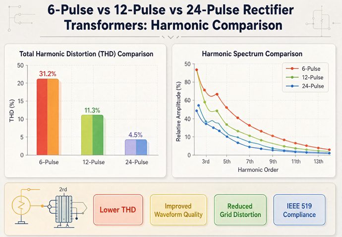
| 6 | 0.09662271 | 31.08 percent | 0.09662104 | Starting point | Starting point |
| 12 | 0.02316292 | 15.22 percent | 0.02316209 | 0.4896 | 51.04 percent |
| 24 | 0.00573120 | 7.57 percent | 0.00573079 | 0.4974 | 50.26 percent |
At 6 pulse the closed form collapses to pi squared over nine minus one. Pi squared is 9.8696, so pi squared over nine is 1.09662, minus one is 0.09662271, and the square root is 0.31084194. That is where 31.08 percent comes from. A completely separate derivation through the distortion factor gives the same thing: three over pi is 0.954930, one over its square minus one is 0.09662271, and the square root is 31.084194 percent. Two routes, one number, and no measured data in either one.
We also summed the series numerically to h equals 200,000. The sums agree within about four parts in ten million and the THD values within 0.0003 percentage points. The small gap is simply the tail of the series that the truncation drops, and it gets relatively larger at 24 pulse because fewer terms sit below the cutoff. For reference, a single phase bridge with a 180 degree square wave current gives the square root of pi squared over eight minus one, or 48.34 percent. A three phase 6 pulse bridge at 31.08 percent is a real improvement over that, but it is not a small distortion by any reading.
Doubling the pulse count halves the distortion, almost
Going from 6 to 12 pulse multiplies the ideal THD by 0.489618, a drop of 51.0382 percent. Going from 12 to 24 pulse multiplies it by 0.497423, a drop of 50.2577 percent. Both are close to a half, but neither is exactly a half, and the second is slightly further from it. If a page says doubling the pulse count halves THD, that is a fair shorthand. If it prints a table with exactly 15.54 percent for 12 pulse and exactly 7.77 percent for 24 pulse, someone rounded the rule instead of doing the sum.
There is a reason the ratio approaches one half. As p grows, the surviving harmonics are pushed to higher orders, and the sum of one over h squared over the surviving orders falls roughly as one over p. The THD, being a square root, falls roughly as one over the square root of p. Doubling p therefore divides THD by the square root of two, which is 1.4142, not by two. The exact ratios here are 0.4896 and 0.4974 because the discrete set of surviving orders matters at small p. This is a detail worth keeping when someone extrapolates a 24 pulse number to 48 pulse by halving it again.
The 62.52 percent that everybody quotes as 80 percent
One page in this search says the 5th and 7th account for more than 80 percent of the distortion in a 6 pulse rectifier, so cancelling them should cut THD by about 80 percent. Neither figure survives a check.
THD is a square root of a sum of squares, so the weight of a pair of harmonics has to be computed on the squares. One over five squared plus one over seven squared is 0.04 plus 0.020408, which is 0.060408. Divide that by the full 6 pulse sum of 0.09662271 and you get 62.519632 percent of the THD squared. That is the correct weight, and it is not 80 percent.
Now remove the pair and see what happens. The remaining sum is 0.02316292, its square root is 15.219369 percent, and the drop from 31.084194 percent is 51.0382 percent. The THD falls by half, not by 80 percent, because the 11th, 13th, 17th and 19th are still there and still contributing. The same arithmetic on the next pair gives 61.225542 percent of the 12 pulse THD squared for the 11th and 13th, and removing them halves the number again. Big first harmonics, halved distortion, two statements that sound contradictory until you remember the square root.
Where the ideal number stops being useful
The 1 over h spectrum assumes a square block of current, a perfectly flat DC current, zero commutation overlap, perfectly balanced AC voltages, exactly equal bridge loads and exact phase displacement. A real drive has a finite DC link inductance, a firing angle, source impedance, and a load that changes minute by minute. Commutation overlap rounds the corners of the current block, which usually lowers the high order magnitudes. Unbalance between bridges leaves residual 5th and 7th that a perfect calculation says should be gone. Firing angle changes the phase of each harmonic relative to the fundamental without changing the order list.
This is why the published THD numbers sit below the ideal ones. A 6 pulse drive quoted at 27 to 35 percent straddles the 31.08 percent ideal, which is a good sanity check on those particular pages. A 12 pulse drive quoted at 6 percent is well below the 15.22 percent ideal, which either means the measurement includes a filter, or the load was light, or the number is TDD rather than THD, or it came from a different denominator entirely. The ideal number is not a target. It is a boundary you can use to ask a better question.
Three denominators in one sentence
Here is where nearly every comparison in this search goes off the rails. Three different ratios get called THD, and they divide by three different things.
| Ratio | Numerator | Denominator | Where it is used |
|---|---|---|---|
| Ideal current THD from 1 over h | Root sum of squares of harmonic currents | Fundamental current I1 at that load | The Fourier derivation in this article |
| Measured current THD | Root sum of squares of measured harmonic currents | Measured fundamental I1 at that instant | A power quality analyser reading |
| TDD in IEEE 519-2022 Table 2 | Root sum of squares of harmonic currents at the PCC | IL, the maximum demand current at the PCC | The compliance limit |
The first and second use I1. The third uses IL. At full rated load with a stiff supply, I1 is close to IL and the two ratios are close. At 30 percent load, I1 is roughly 30 percent of IL and a THD reading can be more than three times the TDD reading for the exact same harmonic current. A vendor quoting 8 percent THD at partial load and a consultant quoting 8 percent TDD at the PCC are not quoting the same quantity even though the number matches.
THD uses I1, TDD uses IL
IL is normally taken as the mean of the twelve monthly peak demand currents at the point of common coupling, though the standard also allows other agreed definitions for new installations. It is a demand figure, not a waveform figure. That choice is deliberate: it stops a plant from looking cleaner simply by running lightly loaded when the meter is running. It also means the compliance number cannot be computed from a single snapshot of the current waveform, no matter how good the analyser is.
The one over h numbers in this article are ratios to I1. When we put them next to the IEEE 519 table later, we say explicitly that we are assuming I1 approximately equals IL at full load. That is an assumption, printed in the open, not a hidden step. Without it, the comparison is apples to oranges, and any page that does the comparison without saying so has quietly made the same assumption without telling you.
The point of common coupling is a place, not a specification
IEEE 519 is a standard about the interface between a utility and a customer. Its current limits apply at the PCC, which is the point where another customer could be connected. That point is usually the metering point or the primary of the service transformer, and it is chosen by agreement, not by the equipment vendor. A rectifier transformer buried three buses downstream of the PCC sees a different impedance, a different mix of other loads and a different harmonic current than the PCC does.
So the honest answer to “does a 12 pulse transformer meet IEEE 519” is that the question is missing a subject. The transformer does not meet or fail the standard. The installation does, at one defined point, over one defined measurement window, against one short circuit ratio. Seven pages in this search mention IEEE 519, and all seven treat it as a property of the pulse number.
Why 1 over h cannot be divided by a TDD limit
We are going to divide 1 over h magnitudes by IEEE 519 Table 2 limits anyway, twice, because that is the only way to show the size of the gap. Both times we flag what the division really is: a comparison of a theoretical harmonic magnitude to a compliance limit, under a stated full load assumption, with no filter and no source impedance. It is not a compliance calculation. A real compliance calculation needs the actual measured spectrum at the PCC, the actual IL, the actual Isc/IL and the statistical evaluation window. What the comparison does tell you, reliably, is that no pulse count on its own gets an unfiltered rectifier anywhere near the tightest row of that table, and that is a purchasing conclusion you can act on.
IEEE 519-2022 Table 2, cell by cell
The current distortion table in IEEE 519-2022 has five bands set by Isc/IL, the ratio of available short circuit current to maximum demand current at the PCC. A stiff supply with a large Isc/IL gets a looser limit. A weak supply gets a tighter one. Within each band the individual harmonic limits are grouped by order, and a total demand distortion limit sits at the end of the row.
Here is the tightest band, Isc/IL less than 20, transcribed from a brand white paper that reproduces the table, with a third column that is our arithmetic. The third column is the ideal 1 over h magnitude for a single characteristic harmonic. The fourth is that magnitude divided by the band limit.
| Harmonic group | Limit for Isc/IL < 20 | Representative order and ideal 1/h magnitude | Times over the limit |
|---|---|---|---|
| 2 through 10, even harmonics limited separately | 4.0 percent | 5th at 20.0000 percent | 5.0000 |
| 2 through 10, same band | 4.0 percent | 7th at 14.2857 percent | 3.5714 |
| 11 through 16 | 2.0 percent | 11th at 9.0909 percent | 4.5455 |
| 11 through 16, same band | 2.0 percent | 13th at 7.6923 percent | 3.8462 |
| 17 through 22 | 1.5 percent | 17th at 5.8824 percent | 3.9216 |
| 17 through 22, same band | 1.5 percent | 19th at 5.2632 percent | 3.5088 |
| 23 through 34 | 0.6 percent | 23rd at 4.3478 percent | 7.2464 |
| 23 through 34, same band | 0.6 percent | 25th at 4.0000 percent | 6.6667 |
| 35 through 50 | 0.3 percent | 35th at 2.8571 percent | 9.5238 |
| Total demand distortion | 5.0 percent | 6 pulse ideal THD at 31.08 percent | 6.2168 |
The 4.55 in our title comes from the third row: the 11th is the first harmonic a 12 pulse bank leaves behind, and at 9.0909 percent it is 4.5455 times the 2.0 percent limit in the tightest band. The 24 pulse bank does worse on its own first survivor. The 23rd at 4.3478 percent sits against a 0.6 percent limit and comes out at 7.2464 times over. Higher pulse count, lower total distortion, larger multiple on the first surviving order. Those three statements are all true at once, and they are the reason the phrase pulse number is not a harmonic limit belongs at the top of this page.
Notice that the limit does not fall smoothly with harmonic order either. It goes 4.0, 2.0, 1.5, 0.6 and 0.3 percent across the five groups. Step from the 19th to the 23rd and the allowance drops by 60 percent while the ideal current magnitude only drops from 5.2632 to 4.3478 percent. That discontinuity is what makes the 24 pulse comparison look so much worse than the 12 pulse one.
The loosest row does not save either design
Now the other end. For Isc/IL greater than 1000 the limits are 15.0, 7.0, 6.0, 2.5 and 1.4 percent across the same five groups, with a 20.0 percent TDD limit. Same ideal magnitudes, new column on the right.
| Harmonic order | Ideal 1/h magnitude | Limit for Isc/IL > 1000 | Times over the limit |
|---|---|---|---|
| 5th | 20.0000 percent | 15.0 percent | 1.3333 |
| 7th | 14.2857 percent | 15.0 percent | 0.9524 |
| 11th | 9.0909 percent | 7.0 percent | 1.2987 |
| 13th | 7.6923 percent | 7.0 percent | 1.0989 |
| 17th | 5.8824 percent | 6.0 percent | 0.9804 |
| 19th | 5.2632 percent | 6.0 percent | 0.8772 |
| 23rd | 4.3478 percent | 2.5 percent | 1.7391 |
| 25th | 4.0000 percent | 2.5 percent | 1.6000 |
| 35th | 2.8571 percent | 1.4 percent | 2.0408 |
| 6 pulse THD | 31.08 percent | 20.0 percent TDD | 1.5542 |
Some individual orders now pass. The 7th, 17th and 19th land under the loose limits. The 11th, the first survivor of a 12 pulse design, is still 1.2987 times over. The 23rd, the first survivor of a 24 pulse design, is still 1.7391 times over. The 6 pulse total is 1.5542 times the loose TDD limit. So even on the friendliest band in the table, with the weakest possible supply constraint removed, an unfiltered rectifier does not close on its own. There is no row in IEEE 519-2022 Table 2 that makes the pulse number sufficient.
That table also shows why a stiff supply helps. Isc/IL greater than 1000 usually means a large upstream fault current relative to the plant demand, so a given harmonic current produces less harmonic voltage at the PCC. The standard rewards that with looser current limits. It does not reward the transformer. A buyer with a weak feeder and a 24 pulse specification can still be further from compliance than a buyer with a stiff feeder and 6 pulse, and no amount of comparing pulse numbers will show it.
How much attenuation would close the gap
Take the four multiples above and turn them into the filter question. If a harmonic sits 7.2464 times over its limit, the required attenuation on that order is a factor of 7.2464, which is 17.2 decibels if you prefer that unit. This is arithmetic on our ideal magnitudes, not a filter specification, and we say so for a reason: a real filter has to be designed against a measured spectrum, a source impedance and a reactive power budget, not against a closed form.
| Design and first survivor | Tightest band, Isc/IL < 20 | Loosest band, Isc/IL > 1000 | What the number is |
|---|---|---|---|
| 12 pulse, 11th at 9.0909 percent | 4.5455 times over, so 4.5455 times attenuation | 1.2987 times over, so 1.2987 times attenuation | Ideal 1/h divided by a table limit |
| 24 pulse, 23rd at 4.3478 percent | 7.2464 times over, so 7.2464 times attenuation | 1.7391 times over, so 1.7391 times attenuation | Ideal 1/h divided by a table limit |
| 6 pulse, 5th at 20.0000 percent | 5.0000 times over, so 5.0000 times attenuation | 1.3333 times over, so 1.3333 times attenuation | Ideal 1/h divided by a table limit |
Read the two columns side by side and the purchasing conclusion writes itself. The short circuit ratio moves the required attenuation by a factor of about three to four on the same design. Moving from 12 pulse to 24 pulse moves the first survivor from 4.5455 times over to 7.2464 times over in the tight band, which is the wrong direction for that particular order. If the filter budget is fixed and the supply is weak, buying more windings can make the filtering job harder, not easier.
Six times over is a comparison, not a compliance test
We should be blunt about the limits of the last three tables. A single harmonic magnitude of 1 over h assumes the fundamental is one per unit and every characteristic harmonic is present at its full ideal value. IEEE 519 Table 2 limits are percent of IL, not percent of I1. The statistical evaluation windows in the standard allow short duration excursions above the table values. The measured spectrum at the PCC includes other loads, background distortion from the utility, and the impedance of the upstream network. Commutation overlap and firing angle shift the real magnitudes away from 1 over h.
So the 6.2168 figure for the 6 pulse total is not a statement that a 6 pulse plant fails IEEE 519 by a factor of six. It is a statement that the ideal distortion of a bare bridge is six times the tightest TDD number in the table, which is a very different thing and still useful. It tells you that compliance is going to come from the system design, the supply stiffness and quite possibly a filter, and that a purchase order which says 12 pulse shall comply with IEEE 519 has assigned a system obligation to a piece of iron.
The 2014 and 2022 editions are not the same rule
Two pages in this search compare the editions, and their reading is consistent with what we could verify. The voltage distortion table did not change. The current table kept the same numbers in the same five bands. What changed is the treatment of even harmonics, the status of the document, and the language of its requirements.
| Item | IEEE 519-2014 | IEEE 519-2022 | Why it matters here |
|---|---|---|---|
| Document status | Recommended practice | Standard | Contract language changes when should becomes shall |
| Even harmonics | Limited to 25 percent of the odd harmonic limits | For h up to 6, 50 percent of the odd limits; above 6, the same limit as odd | Even orders are non characteristic in a balanced bridge |
| Low order current limits | Same numbers, same bands | Same numbers, same bands | A 2022 number does not prove a 2014 calculation wrong |
| Voltage table | 5.0 percent individual and 8.0 percent total at or below 1 kV | Unchanged | Voltage and current limits are different tests |
| Voltage table, 1 to 69 kV | 3.0 percent individual and 5.0 percent total | Unchanged | Applies at the PCC, not at the transformer terminals |
| Scope language | Individual equipment language common in summaries | Installation and PCC framing | The limit belongs to the site, not the rectifier |
Even harmonics changed, and that is not about pulse number
A balanced bridge with symmetrical firing produces only the odd, non triplen orders that h equals kp plus or minus 1 describes. Even harmonics are non characteristic: they show up when something is asymmetric. Unequal firing angles between bridges, DC current ripple, transformer core asymmetry, a voltage unbalance on the supply, or a phase shift that is off by a degree can all produce them. The 2022 edition relaxed the even harmonic treatment at low orders and aligned it with the odd limits above the sixth, which is a change about measurement and asymmetry, not about the characteristic spectrum.
For a buyer this matters in one specific way. A vendor who quotes a harmonic spectrum with only 5th, 7th, 11th and 13th on it is showing you a calculation. A measured spectrum with 2nd, 3rd or 4th on it is showing you a real installation with some asymmetry in it. Both are useful, but they are not the same document, and the second one is the one that belongs in a compliance discussion.
Should became shall, and the subject changed
The name changed from recommended practice to standard, and the modal verbs changed with it. If your specification was written against the 2014 edition, the clause you cite may not read the same in 2022 even though the numeric table cell is identical. Put the edition on the RFQ line, not just the number 519. It costs one word and removes an entire category of bid review argument.
The bigger shift is the subject. The current limits are written for the installation at the PCC. Several pages in this search describe IEEE 519 as a limit on the equipment, which is why they can then write a sentence like a 12 pulse drive meets IEEE 519. That sentence has no defined measurement point, no IL, no Isc/IL and no evaluation window. It is a slogan.
The voltage table did not move
One small piece of good news. The voltage limits at or below 1 kV are 5.0 percent for an individual harmonic and 8.0 percent total, and from 1 to 69 kV they are 3.0 percent and 5.0 percent. Those figures are unchanged between the editions in the transcripts we read. Voltage distortion is the result of harmonic current flowing into the supply impedance, which is why a stiff supply with a high Isc/IL tends to produce less voltage distortion for the same current. If somebody shows you a voltage THD number to prove a current limit was met, ask for the impedance it was computed against.
Statistical percentiles do not rescue a steady overload
The 2022 edition assesses compliance statistically rather than with one worst case reading. The commonly quoted windows allow the 99th percentile daily value to reach twice the table limit, the 99th percentile weekly value to reach 1.5 times, and the 95th percentile weekly value to sit at the table limit itself. Those are short duration allowances for a site whose distortion varies with its process.
Put the loosest steady multiple from our table next to those windows. The 11th harmonic on a 12 pulse design sits at 1.2987 times the loosest band limit continuously while the drive runs at that load. That is below the weekly 99th percentile allowance of 1.5 times, and above the weekly 95th percentile allowance of 1.0 times. A rectifier that runs for eight hours a day is not a short duration excursion. It is the steady state, and the percentile windows were not written to absorb a steady state. The 24 pulse first survivor at 1.7391 times over clears even the 1.5 times weekly window.
This is the part of the standard that a THD table on a vendor page almost never mentions. A single number with no time basis cannot be checked against a statistical rule. Ask for the measurement window and the load profile alongside the number.
Where the measurement belongs
A harmonic study starts at the PCC and works downstream. The short circuit ratio comes from the utility fault current and the plant demand current at that point. The spectrum is measured there, with a class of instrument and a window agreed in advance. Then, if the design needs it, the study repeats the measurement at the rectifier transformer primary to see what the local winding actually carries.
Those two spectra are different, and the difference is the point of this article. On a 12 pulse bank the 5th and 7th can be nearly absent at the common primary and still be present at full magnitude in each of the two secondary windings. A specification that only says THD at the transformer terminals has not said which terminals, on which side, at what load, against which denominator. A specification that says the installation shall comply with IEEE 519-2022 at the PCC, with Isc/IL and IL stated, has said something checkable.
One more practical detail from a vector group page deserves a place here. It lists four sources of non characteristic harmonics: unbalanced loading between bridges, unequal secondary voltages, supply voltage unbalance, and incorrect phasing or wiring. All four are commissioning issues, not design issues. A 24 pulse bank with one group wired 15 degrees out of place will produce a measured spectrum that looks nothing like the ideal one, and no amount of re checking the pulse number on the purchase order will find it. The phase angle belongs on the commissioning checklist.
Phase shift: the formula that actually works
The displacement between adjacent bridge groups is 360 degrees divided by the pulse number p. Equivalently it is 60 degrees divided by k, where k is the number of 6 pulse bridge groups, so p equals 6k. Both forms give the same answer and both are easy to check.
| Pulse count | Bridge groups k | 360 divided by p | 60 divided by k | First surviving order |
|---|---|---|---|---|
| 6 | 1 | 60 degrees | 60 degrees | 5 |
| 12 | 2 | 30 degrees | 30 degrees | 11 |
| 18 | 3 | 20 degrees | 20 degrees | 17 |
| 24 | 4 | 15 degrees | 15 degrees | 23 |
| 36 | 6 | 10 degrees | 10 degrees | 35 |
| 48 | 8 | 7.5 degrees | 7.5 degrees | 47 |
| 60 | 10 | 6 degrees | 6 degrees | 59 |
| 72 | 12 | 5 degrees | 5 degrees | 71 |
| 96 | 16 | 3.75 degrees | 3.75 degrees | 95 |
The last column follows the p minus 1 rule all the way up. A 96 pulse arrangement would leave its first characteristic harmonic at the 95th, which is outside the range that IEEE 519-2022 Table 2 tabulates individually and outside the range of any passive filter you would want to buy. Pulse count stops being a practical lever long before the arithmetic does.
Two formulas in the search results that fail at 12 pulse
One vendor guide gives the phase shift as 30 degrees divided by N over 6, where N is the pulse number. At 12 pulse that is 30 divided by 2, which gives 15 degrees. The correct answer is 30 degrees. Another page gives 30 degrees divided by the number of bridges, which also gives 15 degrees at 12 pulse and also misses. A third page prints both the correct 60 degrees over k and the incorrect 30 degrees over the bridge count in the same article without noticing that they disagree.
We recomputed both wrong forms and put the result in the table above so the failure is visible rather than asserted. At 12 pulse the two bridges are 30 degrees apart, not 15. If a design really used 15 degrees between two groups, the 5th and 7th would not cancel at the primary and the installation would behave like a badly built 6 pulse drive. This is a one line check that any reviewer can do before the submittal goes back.
Four bridges, four angles
For 24 pulse the four groups sit 15 degrees apart. One source writes 0, 15, 30 and 45 degrees. Another writes minus 22.5, minus 7.5, plus 7.5 and plus 22.5 degrees. Subtract 22.5 from the first set and you get minus 22.5, minus 7.5, plus 7.5 and plus 22.5. They are the same four angles with a different zero reference, and both are consistent with a 15 degree step. That is a nice example of two pages that look like they contradict each other but actually agree, and it is worth checking before you send an RFQ that specifies one of the two sets as if the other were wrong.
The tolerance question is the harder one. At 6 pulse a one degree winding error is 1.7 percent of the 60 degree displacement. At 24 pulse the same one degree error is 6.7 percent of the 15 degree step. The higher the pulse count, the more the cancellation depends on winding ratio accuracy, tap matching, bridge balance and identical DC loading. This is the engineering reason the published THD numbers spread so widely at 24 pulse, and it is also why a 24 pulse bank can measure worse than a well built 12 pulse bank in the field.
What the phase shift does not fix
Phase shift cancels characteristic harmonics at the point where the shifted currents combine. It does not change the current waveform drawn by any individual bridge, it does not remove the harmonics from the secondary windings, it does not correct supply voltage unbalance, and it does not fix a DC bus that is not sharing current equally. It also does not change the total kVA the transformer has to carry, and four secondaries with tightly matched impedances cost more to build than two. Keep those three separate questions on the RFQ: what the PCC sees, what each winding carries, and what the site actually measures.
Where the cancelled harmonics go
A 12 pulse transformer makes the 5th and 7th disappear from the common primary. It does not make them disappear from the machine. Each secondary bridge still draws a 120 degree block of current with a full 5th and 7th in it, and those currents still flow through that secondary winding, through its leads and through its portion of the DC bus. What cancels is the sum at the primary, not the heating in the copper.
This is the single most useful fact that the comparison pages leave out, because it explains two things at once: why converter duty transformers are rated differently from ordinary distribution transformers, and why a good harmonic loss calculation uses the spectrum at each winding rather than the spectrum at the PCC. A university thesis in this search says it in one sentence and moves on. IEEE C57.18.10 and IEC 61378-1 build a whole testing approach around it.
One over h meets h squared
Winding eddy current loss scales roughly with the square of the harmonic current times the square of the harmonic order. Take the ideal spectrum at face value: the current at order h is 1 over h relative to the fundamental. Squared, that is 1 over h squared. Multiply by h squared and the result is one. Every characteristic harmonic in the ideal 1 over h spectrum contributes the same eddy term as the fundamental does.
That is a clean, surprising result, and it is worth writing out because it kills a common claim. A page that says the 5th harmonic produces four times the eddy loss of the fundamental has multiplied by something twice or forgotten the 1 over h decay. With the ideal spectrum, 25 times one twenty fifth is exactly 1.0000, which is the same contribution as the fundamental, not four times it.
Now count the terms, truncating at h equal to 50 because IEEE 519-2022 Table 2 stops tabulating individual orders there and because higher orders contribute little to a real winding. Add one for the fundamental.
| Design | Characteristic orders at or below 50 | Weighted terms including the fundamental | Reduction from the previous design |
|---|---|---|---|
| 6 pulse | 16 | 17 | Starting point |
| 12 pulse | 8 | 9 | 47.0588 percent |
| 24 pulse | 4 | 5 | 44.4444 percent |
Cut the count in half twice and the weighted eddy term goes 17 to 9 to 5. The ratios are 9 over 17, which is 0.529412, and 5 over 9, which is 0.555556. Compare those with the THD ratios of 0.489618 and 0.497423 in the earlier table. Three different metrics, three different drop rates: THD falls 51.04 percent from 6 to 12 pulse, eddy weighted terms fall 47.06 percent, and the first surviving harmonic order jumps from 5 to 11. A specification that says harmonic losses will be 50 percent lower is mixing at least two of those.
The truncation at h equals 50 is our choice, not a standard’s. It is stated here so anyone can redo the count with a different cutoff. The qualitative result does not change: cancelling low orders at the primary removes fewer weighted loss terms than it removes THD, because the high orders that remain still carry their full h squared weighting.
Three different drop rates for three different metrics
Put the three metrics in one place and the pattern is easier to hold onto. THD is a root sum of squares of current magnitudes. Eddy loss is a sum of h squared times current squared. The compliance limit is a table of percentages by order with a discontinuity between the 22nd and the 23rd. Nothing says these three should improve at the same rate, and they do not.
This is also why the phrase twenty four pulse gives half the harmonics of twelve pulse is so unhelpful. It gives half the weighted terms under our truncation, half the THD under the ideal spectrum, twice the first surviving order, and a worse multiple against the compliance table. A buyer who needs one of those four outcomes has to name which one.
C57.18.10 Annex B works one example
A secondary reading of IEEE C57.18.10-2021 describes Annex B with a 2,700 kVA converter transformer example. The base loss calculation gives 28,452 W and the calculation with the harmonic spectrum gives 36,904 W. That is an increase of 8,452 W, or 29.7062 percent, not the round 30 percent that some summaries print. The same reading gives a winding eddy loss factor FHL-WE of 1.4356 and an other stray loss factor FHL-OSL of 1.1930 for a 12 pulse secondary.
We report those numbers as published on the secondary page, not as standard text. We did not buy the standard. What they illustrate is the shape of the calculation: take the sinusoidal loss, split it into winding eddy and other stray components, apply a harmonic loss factor computed from the actual spectrum at that winding, and add the results. The 12 pulse secondary gets a factor above one precisely because its own 5th and 7th are still there even though the primary is clean.
The 2021 revision is also described as moving away from the older approach. The 1998 edition is said to have rated converter transformers in rms kVA with an empirical 60 over 40 split between eddy and stray loss. The 2021 edition is described as carrying both rms and fundamental kVA designations and using field analysis plus explicit FHL-WE and FHL-OSL factors. We could not verify the clause wording, so we treat the version comparison as a secondary account. The interval between the two edition years, 1998 to 2021, is 8,401 days if you take January 1 of each year as the arithmetic dates, and that is an edition label gap, not a compliance date.
The numbers vendors actually publish
Here is the part of the search that should make any buyer slow down. We collected the THD figures attached to each pulse count across six pages, put them in one column, and did not normalise anything.
| Pulse count | Published THD figures in this search | Lowest to highest | Spread as a ratio | Ideal THD for comparison |
|---|---|---|---|---|
| 6 | 27, 28, 30, 31 and 35 percent | 27 to 35 percent | 1.2963 times | 31.08 percent |
| 12 | 6, 7, 8, 10, 12, 13 and 15 percent | 6 to 15 percent | 2.5 times | 15.22 percent |
| 24 | 2, 3, 4.4, 5 and 6 percent | 2 to 6 percent | 3.0 times | 7.57 percent |
The 6 pulse figures cluster around the ideal 31.08 percent, which makes sense. The 12 pulse figures spread from 6 percent, well below the ideal 15.22 percent, up to 15 percent, which is the ideal. The 24 pulse figures spread by a factor of three. There is no single correct value in either column, because none of these pages is quoting the same measurement.
The academic thesis we mentioned earlier says that getting distortion below 4.5 percent rarely pays for the extra cost. Several vendor pages quote 2 to 3 percent for 24 pulse. Those two statements can both be true if one is talking about measured THD at a stiff PCC with a filter and the other is talking about the marginal cost of the last few percent. Without the conditions, they are just two numbers fighting.
Four conditions that would make those numbers comparable
Ask for these four things and the spread usually collapses.
- The measurement point. At the PCC, at the transformer primary, or at one secondary bridge. The 5th and 7th answers are completely different at those three places on the same 12 pulse bank.
- The load point. THD uses I1 as its denominator and changes with load. A figure at 25 percent load and a figure at full load are not comparable, and the ideal 1 over h spectrum assumes full, steady conduction.
- The denominator and the ratio name. THD, TDD, or a voltage THD. A TDD divided by IL at light load can look half as large as a THD divided by I1 for the same harmonic current.
- Everything between the bridge and the meter. A line reactor, a DC link choke, a passive filter, an active filter, other loads on the same bus, and the upstream short circuit ratio. A 6 percent figure for 12 pulse often has a filter in the circuit and does not say so.
A fifth thing is worth adding even though it is not a number: the edition of IEEE 519 and the evaluation window if the figure is being offered as a compliance claim. A single snapshot against a statistical standard is not a compliance result.
DC ripple frequency is the easy part
The DC side ripple frequency is the pulse count times the line frequency. That part is pure arithmetic and every page that gives it agrees.
| Line frequency | 6 pulse | 12 pulse | 24 pulse |
|---|---|---|---|
| 50 Hz | 300 Hz | 600 Hz | 1200 Hz |
| 60 Hz | 360 Hz | 720 Hz | 1440 Hz |
At 60 Hz, a 24 pulse drive puts a 1440 Hz ripple on the DC bus. That is easier to smooth than 360 Hz, and it is a real benefit for the DC link design. What is not settled is the ripple amplitude. Three pages in this search give three different amplitude figures for the same three pulse counts, and we could not find a primary source that reconciles them, so we are not printing any. Frequency is checkable; amplitude needs a load, a firing angle and a DC link impedance.
Displacement factor is not true power factor
The 120 degree current block has a displacement factor of three over pi, which is 0.954930, when the fundamental current is in phase with the voltage. Its distortion factor is one over the square root of one plus the THD squared, and with a THD of 31.08 percent that also works out to 0.954930. Multiply them and true power factor is 0.9119. If the displacement factor is 0.95 rather than 0.9549, the product is 0.9072. Either way, a 6 pulse drive with about 31 percent current THD is not running at 0.95 power factor, and a data sheet that quotes 0.95 without saying which factor it means has quoted the displacement factor.
This matters for the kVA conversation. A 0.91 true power factor means more apparent power for the same kW, more current in the transformer and more current in the upstream feeder. It is also a reminder that the harmonic discussion is not only about a compliance table. It is about copper, losses and the size of the switchgear upstream.
Five arithmetic errors to cross off a spec sheet
These five showed up in the pages we read. Each one is checkable in under a minute, and each one would change a purchase decision if it were believed.
| Claim seen in the search | What the arithmetic says | Consequence |
|---|---|---|
| A 12 pulse bank cancels the 17th and 19th | h equals 12k plus or minus 1 leaves 11, 13, 23 and 25. The 17th and 19th are 18 pulse orders, not 12 pulse orders | A filter tuned to the wrong pair |
| A 24 pulse bank eliminates harmonics up to the 23rd | The 23rd is p minus 1, the first survivor, at 4.3478 percent ideal magnitude | No filter specified for the dominant remaining order |
| Phase shift is 30 degrees divided by N over 6 | At 12 pulse it gives 15 degrees. The correct value is 360 divided by 12, which is 30 degrees | The 5th and 7th do not cancel at the primary |
| The 5th and 7th are over 80 percent of the distortion | Their share of THD squared is 62.519632 percent, and cancelling them cuts THD by 51.0382 percent | A promised 80 percent reduction that cannot happen |
| The 5th harmonic adds four times the eddy loss | h squared times one over h squared is 1.0000 for every ideal characteristic order | An inflated or missed loss allowance |
Two of those are mistakes about which harmonic exists. Two are mistakes about what a percentage means. One is a formula that fails on the most common pulse count in the market. None of them requires a standard to check.
Cost claims and what they are worth
Several pages attach prices to pulse counts. A 24 pulse arrangement is said to cost 1.5 to 2 times a 12 pulse one. Each doubling of pulse count is said to add 35 to 50 percent. Adding more windings is said to cut filter cost by 60 to 70 percent. One page quotes an active front end as a cheaper alternative at 3 percent THD. We could not find a bill of materials, a dated quote, a currency, a capacity or a scope behind any of those figures.
We are labelling all of them L3, which in our grading means a number we will report as a claim but will not use as a requirement. The one source with an actual engineering argument is the university thesis, which says the improvement below 4.5 percent rarely pays for the additional cost and lists the reliability penalty of more devices. That is a conclusion with reasoning attached, not a percentage with no denominator. If cost matters, ask for the price difference on your own kVA, your own voltage and your own enclosure, with the filter scope stated on the same line.
Sources, graded
Here is the evidence ledger for this article. L1 means we could read the primary document or a full transcription of it. L2 means a named secondary source with a traceable derivation. L3 means a vendor or aggregator number we report but do not rely on.
| # | Source | Grade | What we took from it | What we did not take |
|---|---|---|---|---|
| 1 | Siemens harmonic white paper, IEEE 519-2022 Table 1 and Table 2 transcription | L1 | Five Isc/IL bands, group limits, TDD limits, voltage table | No clause wording beyond the transcript |
| 2 | IEEE 519-2022 edition change summaries from two power quality consultants | L2 | Even harmonic treatment, should to shall, statistical percentiles | No full standard text |
| 3 | University thesis, 12 pulse line current Fourier series | L1 | 5th and 7th cancellation, 12k plus 1 positive sequence, cost conclusion | No general THD table |
| 4 | Power electronics course notes and a 6 pulse harmonic analysis paper | L1 | Is 0.8165 Id, Is1 0.7797 Id, DF 3 over pi, THD 31.08 percent | No measured field data |
| 5 | IEEE C57.18.10-2021 Annex B secondary reading | L2 | 28,452 to 36,904 W, FHL-WE 1.4356, FHL-OSL 1.1930 | No clause text, no full standard |
| 6 | IEC 61378-1:2011 scope descriptions in vendor guides | L2 | Harmonic spectrum based loss calculation | No test procedure detail |
| 7 | Rectifier manufacturer 12 MW electrolysis worked example | L2 | Udi0 1.35 Uv0, Iv 0.816 Id, S about 1.05 Udi0 Id, h squared weighting | No price or delivery data |
| 8 | Vendor phase shift tables and vector group pages | L2 | Four 24 pulse angles, non characteristic harmonic causes | The 30 over N over 6 formula, which fails |
| 9 | Power quality measurement guide on TDD | L2 | IL definition, twelve monthly peak demands, percentile windows | No single reading treated as compliance |
| 10 | Published THD tables on six vendor and content pages | L3 | 27 to 35, 6 to 15 and 2 to 6 percent spreads | No figure used as a requirement |
| 11 | Cost and filter saving percentages on vendor pages | L3 | Reported as claims only | 1.5 to 2 times, 35 to 50 percent, 60 to 70 percent not used |
| 12 | Closed form, numeric sums, ratios, angle table and Table 2 multiples in this article | Our arithmetic | 31.084194, 15.219369, 7.570471 percent and every multiple in the tables | Not a measurement, not a standard value |
A copy paste RFQ block
Fifteen lines. Paste them into the enquiry and make the supplier answer each one. The lines are ordered so that the first six settle what is being bought, the next five settle what is being measured, and the last four settle what proves it.
- State the rectifier duty, DC voltage, DC current, kVA and whether this is a rectifier transformer or a phase shifting transformer with separate bridges.
- State the pulse count, the number of bridge groups and the vector group of every secondary winding.
- State the phase displacement between adjacent groups in degrees and the measurement tolerance on that angle.
- State the standard and edition used for the harmonic calculation, and the standard and edition used for any compliance claim.
- State the load point at which every quoted THD or TDD figure applies, from 25 percent to 100 percent rated load.
- State the firing angle range, DC link inductance and any line reactor between the bridge and the transformer.
- State whether each quoted figure is THD with I1 as denominator, TDD with IL as denominator, or voltage THD, and give the denominator value.
- State the measurement point for each figure: PCC, transformer primary, or one secondary bridge.
- State Isc and IL at the PCC and give the resulting Isc/IL band used with IEEE 519-2022 Table 2.
- State the individual harmonic spectrum up to the 50th, including non characteristic and even orders, at full load.
- State the measurement window, instrument class and statistical percentile used for any compliance claim.
- Give the harmonic loss factors used for each winding, with the spectrum they were computed from.
- Give the guaranteed loss in watts at rated load with that spectrum, and the temperature rise test method behind it.
- Give the harmonic study report number, the laboratory or consultant, and the date of the study.
- State what is included in the quoted scope: filters, reactors, interphase reactors, protection, enclosure and commissioning phase angle verification.
Ten dates that belong in different columns
A standard number without an edition is not a citation. A rule without a date is not a requirement. Three dates that look similar do three different jobs: the day a document was published, the day it was adopted somewhere else, and the day a rule starts to bind. Keep them apart.
| # | Event | Date | Interval | What it is not |
|---|---|---|---|---|
| 1 | IEEE 519-1992 edition | 1992, year only | Starting point of the modern series | Not the current edition |
| 2 | IEEE C57.18.10-1998 edition | 1998, year only | 8,401 days before the 2021 edition year | Not a PCC harmonic limit |
| 3 | IEC 61378-1:2011 | 2011, year only | Converter transformer loss calculation standard | Not IEEE 519 |
| 4 | IEEE 519-2014 published | June 2014, day not verified | 2,983 days before the 2022 edition | Not the current even harmonic rule |
| 5 | EU 548/2014 Tier 2 applies | July 1, 2021 | 1,960 days before this article | Not a harmonic rule |
| 6 | IEEE C57.18.10-2021 edition | 2021, year only | 2,141 days before this article | Not a compliance deadline |
| 7 | IEEE 519-2022 published | August 2022, day not verified | 1,564 days before this article | Not the 2014 edition |
| 8 | Date of this article | November 12, 2026 | 4,547 days after the 2014 edition date used here | Not any of the above |
| 9 | US federal efficiency compliance date | April 23, 2029 | 893 days after this article | Carried over from earlier work, not re verified |
| 10 | Edition label gap 1992 to 2022 | 30 years by edition year | A label gap, not a day count | Not a compliance window |
Every interval is computed from the dates printed in the table, using June 1, 2014 and August 1, 2022 as arithmetic stand ins for the two edition months, and January 1 for the two edition years in row 2. The publisher’s exact day is not verified here for either IEEE 519 edition. From 2014 to 2022 is 2,983 days, from 2014 to this article 4,547 days, from 2022 to this article 1,564 days, from the 2021 C57.18.10 edition to this article 2,141 days, and from this article to the federal date 893 days. If a date sits on a purchase order, get it from the publisher’s current page.
Rows 5 and 9 are in this table for one reason only. Both are efficiency rules that show up in the same specification sections as harmonic limits. Neither changes a Table 2 value. A submittal that lists Tier 2, a pulse count and a TDD limit as if they were three rungs of one ladder has merged three documents.
Bring this to the specification meeting
The whole answer in one place
If you have five minutes in a design review, say this. Pulse number is not a compliance limit. The ideal current THD of a bare bridge is 31.08 percent at 6 pulse, 15.22 percent at 12 pulse and 7.57 percent at 24 pulse, all from the square root of a closed form sum of one over h squared. The first surviving harmonic is p minus 1, so it is the 5th, the 11th and the 23rd, and those three sit at 20.0000, 9.0909 and 4.3478 percent. Against the tightest IEEE 519-2022 Table 2 band the 11th is 4.5455 times over and the 23rd is 7.2464 times over; against the loosest band they are still 1.2987 and 1.7391 times over. The phase shift between adjacent bridge groups is 360 degrees divided by the pulse count, which gives 60, 30 and 15 degrees, not the 15 degrees that two published formulas give for 12 pulse. The 5th and 7th cancel at the common primary but still heat each secondary, so weighted eddy terms go 17 to 9 to 5, a drop of 47.0588 and 44.4444 percent, which is not the same as the 51.04 percent THD drop. IEEE 519 limits the installation at the PCC with IL as the denominator, and the one over h numbers use I1. Put the edition, the short circuit ratio, the measurement point, the load point and the denominator on five separate lines of the RFQ.
That is the whole article in one paragraph. Everything else here is the evidence for one of those sentences.
What actually costs money is what sits between the lines. One pulse count is quoted with THD values spanning 6 to 15 percent at 12 pulse and 2 to 6 percent at 24 pulse. One table cell changes the required attenuation from 7.2464 times to 1.7391 times depending on Isc/IL. One bridge group wired a degree off puts non characteristic harmonics into a measured spectrum that the ideal formula never predicted. One harmonic pair is described as 80 percent of the distortion when its share of THD squared is 62.519632 percent and removing it cuts THD by 51.0382 percent. One Annex B example adds 8,452 W, or 29.7062 percent, to the loss of a 2,700 kVA converter transformer. Six of these are document failures, not engineering failures, and every one is catchable with a single question before the order is released.
Twelve numbers worth keeping
| Number | What it decides |
|---|---|
| 31.08, 15.22 and 7.57 percent | Ideal THD for 6, 12 and 24 pulse from the closed form |
| 0.09662271 and pi squared over nine minus one | The 6 pulse sum and the derivation behind 31.08 percent |
| 0.489618 and 0.497423 | What doubling the pulse count actually does to THD |
| 5, 11 and 23 | The first surviving harmonic order at each pulse count |
| 20.0000, 9.0909 and 4.3478 percent | Ideal magnitude of each first survivor |
| 4.5455 and 7.2464 times | Those first survivors against the tightest IEEE 519-2022 band |
| 1.2987 and 1.7391 times | The same two harmonics against the loosest band |
| 60, 30 and 15 degrees | Correct phase shift, and 15 degrees is the wrong answer at 12 pulse |
| 17, 9 and 5 | Weighted eddy terms at h up to 50, dropping 47.0588 and 44.4444 percent |
| 62.519632 and 51.0382 percent | The real weight of the 5th and 7th, and the real THD drop |
| 8,452 W and 29.7062 percent | Annex B loss increase from 28,452 to 36,904 W |
| 2.5 and 3.0 times | Spread of published THD at 12 and 24 pulse |
Keep the first row for the quotation, the second for anyone who wants to see the derivation, and the third for the person who says doubling halves it exactly. Keep 5, 11 and 23 for the filter conversation, and the three magnitudes for the compliance conversation. Keep both pairs of multiples and remember they are comparisons against a table, not compliance results. Keep the three angles for the winding drawing and the wrong 15 degrees for the submittal review. Keep 17, 9 and 5 for the loss conversation, because they do not fall at the same rate as THD. Keep 62.519632 and 51.0382 percent for the sales meeting. Keep 8,452 W for the thermal budget. Keep 2.5 and 3.0 times as the reason to ask for the four measurement conditions before believing any single THD figure.
Those numbers fit on one page of a bid review, and each one can be recomputed from the figures on the sheet in front of you. If you have a single line diagram, a draft specification, two quotations and a measured spectrum, send them over. We will tell you which pulse count each number belongs to, which denominator it uses, which Isc/IL band applies at your PCC, and which of the fifteen RFQ lines still need an answer before the order is released. Start here.
FAQ
Does a 12 pulse transformer meet IEEE 519-2022?
Not by itself. IEEE 519-2022 limits the whole installation at the PCC, not the transformer. On the tightest band the 11th harmonic at 9.0909 percent is 4.5455 times the 2.0 percent limit, and even on the loosest band it is 1.2987 times over. You also need Isc/IL, IL and the measurement window.
What is the ideal current THD of a 6 pulse bridge?
31.084194 percent. It falls out of pi squared over nine minus one, which is 0.09662271, and its square root is 0.31084194. A separate route through the distortion factor three over pi, or 0.954930, gives exactly the same number. A single phase bridge gives 48.3426 percent.
Which harmonics does a 12 pulse bank cancel at the primary?
The 5th and the 7th. Two 6 pulse bridges 30 degrees apart cancel those orders in the common primary winding. The surviving orders follow h equals 12k plus or minus 1, so the first four are 11, 13, 23 and 25. The 5th and 7th still flow in each secondary.
What is the first harmonic left by a 24 pulse bank?
The 23rd, at 4.3478 percent of the fundamental under the ideal one over h spectrum. The rule is p minus 1. A data sheet saying harmonics up to the 23rd are eliminated has it backwards, and that mistake can leave the dominant remaining order with no filter specified.
What phase shift does a 12 pulse transformer need?
30 degrees between adjacent bridge groups, from 360 divided by 12. Two published formulas give 15 degrees at 12 pulse, one by dividing 30 by N over 6 and one by dividing 30 by the number of bridges. At 15 degrees the 5th and 7th would not cancel at the primary.
What is the difference between THD and TDD?
THD divides the root sum of squares of harmonic currents by the fundamental I1 at that instant. TDD divides by IL, the maximum demand current at the PCC, often the mean of 12 monthly peaks. At 30 percent load the same harmonic current can give a THD more than 3 times the TDD.
How far over the tightest IEEE 519-2022 band is the 11th?
4.5455 times. The ideal 11th is 9.0909 percent and the Isc/IL less than 20 band allows 2.0 percent for orders 11 through 16. The 23rd is 7.2464 times over its 0.6 percent band, so a 24 pulse design can look worse on its own first survivor.
Does a stiff supply make the pulse count sufficient?
No, though it helps. At Isc/IL greater than 1000 the 11th drops to 1.2987 times over and the 23rd to 1.7391 times over, from 4.5455 and 7.2464. The 6 pulse total is 1.5542 times the 20.0 percent TDD limit. No band in Table 2 makes an unfiltered design compliant.
Do cancelled harmonics still heat the windings?
Yes. Winding eddy loss scales with h squared times harmonic current squared, and with a one over h spectrum that product is 1.0000 for every characteristic order. Counting to h equals 50 gives 17 weighted terms at 6 pulse, 9 at 12 pulse and 5 at 24 pulse, a drop of 47.0588 and 44.4444 percent.
What is the DC ripple frequency at 60 Hz?
360 Hz at 6 pulse, 720 Hz at 12 pulse and 1440 Hz at 24 pulse. The rule is pulse count times line frequency, so at 50 Hz the three are 300, 600 and 1200 Hz. Ripple amplitude depends on firing angle and DC link impedance, and the published amplitude figures we found disagree.
How much do published THD figures vary for one pulse count?
At 12 pulse the figures in this search run from 6 to 15 percent, a factor of 2.5. At 24 pulse they run 2 to 6 percent, a factor of 3.0. At 6 pulse they run 27 to 35 percent, a factor of 1.2963. No page stated the load point, denominator and measurement point together.
Does doubling the pulse count halve THD?
Almost, not exactly. The 6 to 12 ratio is 0.489618 and the 12 to 24 ratio is 0.497423, so the drops are 51.0382 and 50.2577 percent. THD falls roughly as one over the square root of pulse number, which is why halving it again at 48 pulse is not a safe extrapolation.
What should the RFQ say?
15 lines: duty and kVA, pulse count and vector groups, phase angle and tolerance, standard and edition, load point, firing angle and reactors, ratio name and denominator, measurement point, Isc and IL, spectrum to the 50th, measurement window, harmonic loss factors, guaranteed watts, study report, and quoted scope.