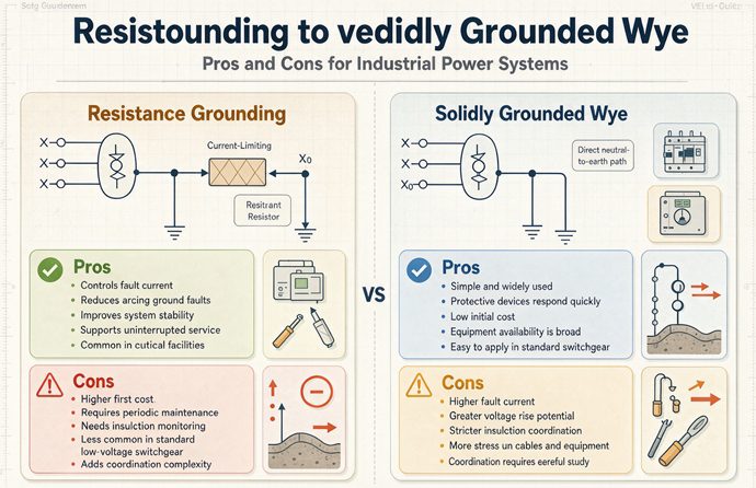
Choosing between resistance grounding and a solidly grounded wye is not a pros and cons exercise. Three gates decide it first: whether any load connects line to neutral, which voltage band you are in, and how much charging current the cables add. Then you pick a number, and that number runs from 5 A to 2,000 A, a 400 times spread.
If you came from one of our other transformer pages, this is the one about the choice before the connection. The grounded wye page compares two grounding philosophies. The X0 page sizes the jumper at the terminal and walks through the bonding point. Neither one tells you whether a resistor belongs in that path at all, or which of eleven published current ranges your plant actually needs. That is all we do here. No terminal lugs, no conductor tables, no pricing.
The short answer, before the pros and cons
Here is the six row comparison shape search engines like to pull, with the adjectives replaced by the gate that actually answers the question and a number you can check before you order anything.
| If your question is | What actually answers it | Number to check | What goes in the spec |
|---|---|---|---|
| Can I use a resistor at all | Gate one: is there a line-to-neutral load | 277 V is 1.8467 times the 150 V trigger | Load schedule, in writing |
| Which section applies | Gate two: 480 to 1,000 V, or above 1,000 V | 1,000 / 480 = 2.0833 times | System voltage and section number |
| What current do I set | Gate three: measured system charging current | 0.525 A versus 9.325 A, 17.76 times | Charging current study or measurement |
| Will the breaker see it | A 230.95 pickup or a neutral overvoltage relay | 1,200 A over 5 A = 240 times | Sensing scheme and CT locations |
| What does continuity cost | 173.21 percent on the two healthy phases | 480 V on a 300 V cable = 1.60 times | Insulation and arrester review |
| What does the resistor cost | Duty in watts and a time rating | 1,385.64 W continuous, not 10 s | Rated voltage, current, and time |
Read the second column top to bottom. Not one row says “better safety” or “lower cost.” Every answer is a load type, a voltage band, a measured current, a sensing device, an insulation level, or a resistor rating. That is why a two column list of advantages and disadvantages cannot answer the question in the title. It compares two things that were never defined to the same level of detail.
Why a two column table cannot decide this
A pros and cons table assumes both columns describe one product each. A solidly grounded wye is one product. It has a neutral bonded to ground with no intentional impedance, and its ground fault current is whatever the system impedance allows, often tens of thousands of amperes. Resistance grounding is not one product. It is a family of designs whose let-through current is chosen by the engineer, and the published answers run from 5 A to 2,000 A.
Put those two things side by side and the comparison breaks in a specific way. Every “pro” of resistance grounding belongs to the low end of that range, where the fault only alarms and the plant keeps running. Every “pro” that involves selective tripping belongs to the high end, where the fault is cleared in seconds. Those are opposite behaviours. A table that lists “continuity of service” and “selective coordination” as two benefits of the same option is describing two systems that would never be built the same way.
The second problem is that the most important “con” is not a drawback at all. It is a gate. If your 480Y/277 V system feeds 277 V lighting, high resistance grounding is not a slightly worse option with a longer payback. It is not permitted. The three conditions in NEC 250.36 and the mandatory grounding rule in 250.20(B) settle that before anybody opens a spreadsheet. We will walk through that gate first, because it removes roughly half the projects people bring us.
What the ten ranking pages agree on
Give the search results their due. Ten pages, from transformer makers to a calculator site to an IEEE chapter training deck, agree on the physics. A solidly grounded neutral gives a low impedance return path, so a phase to ground fault draws enough current to open an overcurrent device fast. An impedance in that neutral path limits the current, so the first fault can be alarmed instead of cleared. Unfaulted phases rise toward line to line voltage above ground. Ungrounded systems can build destructive transient overvoltages from restriking faults. All of that is correct, and we are not going to re-argue it here.
They also agree on the application split. Offices, hospitals and data centers with 277 V lighting or 120 V receptacles stay solidly grounded. Process plants, mines, paper mills and medium voltage motor buses with three wire loads are where resistance grounding shows up. Three of the ten even quote the same sentence from IEEE 141 about the 480 V and 600 V solidly grounded system having the highest probability of escalating into a phase to phase arcing fault.
Where they part company is the number. Ask ten of them what “resistance grounding” limits the fault to and you get eleven answers, because one of them gives two in the same paragraph.
The one number they all print and none of them defines
Every page prints a fault current. Almost none prints the time that current flows, the charging current sitting underneath it, or the relay that is supposed to see it. That missing trio is where the money goes. A 5 A figure with a 10 second resistor rating is a different machine from a 5 A figure with a continuous rating. A 5 A figure on a plant with 0.525 A of charging current is a working design; the same 5 A on a plant with 9.325 A is an expensive ungrounded system with a resistor attached. And a 5 A fault will never reach a ground fault relay set anywhere near the 1,200 A ceiling in 230.95.
We are going to recompute all three, then come back to the pros and cons with the conditions attached.
Seven checks, in the order a design actually makes them
- Pull the load schedule and mark every line to neutral load. One 277 V lighting circuit, one control transformer, one receptacle fed from the neutral, and high resistance grounding is off the table on that bus.
- Write down the system voltage and decide which section governs. The 480 V to 1,000 V band is 250.36. Above 1,000 V it is 250.187, where the impedance grounding conductor has to be insulated for the maximum neutral voltage.
- List the qualified persons and the ground detectors. Both are conditions of 250.36, not suggestions, and both belong in the specification rather than on a drawing note.
- Estimate or measure the total system charging current, 3Ic0. Sum the shielded cable footage, transformer, motors and surge capacitor sets. If you are converting an existing plant, measure it.
- Choose the let-through current at or slightly above that charging current, then compute the resistor ohms from line to neutral volts divided by that current. Remember that the fault current is the vector sum of the resistor branch and the capacitive branch, so it is larger than the number on the resistor nameplate.
- Decide what happens on the first fault. Alarm and keep running calls for a 59G or device 64 neutral overvoltage relay, ground detectors and a pulsing contactor. Trip selectively calls for 51G or 50G with core balance CTs. Do not write both into the same scheme.
- Check the equipment that has to survive the fault: cable insulation, surge arresters, MOV ratings on drives, breaker single pole duty, the neutral insulation on the transformer, and every other source on the bus including generators and tie breakers.
Why step one comes before the resistor catalog
Because it is the only step that can delete the entire design. NEC 250.20(B) requires grounding on 50 V to 1,000 V systems where the maximum voltage to ground can be held to 150 V or less, on three phase four wire wye systems that use the neutral as a circuit conductor, and on four wire delta systems with a midpoint. A 480Y/277 V service feeding lighting is squarely in that list. The 277 V line to neutral voltage is 1.8467 times the 150 V figure, and the neutral is a circuit conductor by definition on a four wire wye.
NEC 250.36 then permits a high impedance grounded neutral system on three phase AC systems from 480 V to 1,000 V only where three conditions hold: qualified persons service the installation, ground detectors are installed, and line to neutral loads are not served. The third condition is the one that kills retrofits. It is written as a condition of using impedance grounding at all, not as a design preference, and it applies to the whole system. Adding one 277 V fixture back after the conversion puts that fixture in series with the resistor during a fault on another phase.
There is a practical reason behind the blanket rule. During a first line to ground fault on an impedance grounded system, the neutral is no longer at ground potential. The two unfaulted phases rise to line to line voltage above ground, which is 1.7321 times their normal line to ground voltage. A device connected from a phase to that neutral would see a voltage the code panel did not want to verify across every possible load. So it wrote a simple prohibition instead.
Why step four is the one that gets skipped
Charging current is not on the one line diagram. It is a property of the cable footage, the transformer, the motors and the surge capacitors, and it changes when somebody adds a feeder. A published field case describes a 5 kV plant where the switchgear schedule called for 5 A high resistance grounding with a 10 second resistor, the contractor installed exactly that, and nobody measured charging current. Shielded 5 kV cable, surge arresters and drive input filters added up to roughly 6.8 A. On the first phase to ground fault the sensing relay never saw the rise, and the plant ran for two days with a grounded phase. The second fault, on a different phase, became a phase to phase arcing event. Everything had been built to the drawing.
That story is the whole argument for this section. The resistor was correct. The scheme was not. We will recompute the arithmetic behind it in the gate three section, including the vector sum that makes a nominal 5 A resistor carry more than 5 A.
Why step six is a decision, not a relay setting
One ranking page says the ground fault sensor must de-energize the system within a time delay, and specifies one hour at the service with 30 minutes on the feeders. Another says plainly that installing a trip on the first ground fault means you have paid for high resistance grounding and built low resistance grounding. Those two statements describe different systems. The first is describing a scheme that eventually clears; the second is describing the alarm only scheme that makes continuity possible in the first place.
The 250.36 conditions we could verify do not include a mandatory trip on the first fault. They include qualified maintenance, ground detectors, and no line to neutral loads. A fourth condition about continuity of service being required appears in one training PDF. We are not going to resolve which edition says what, because the adopted edition was not verified for this article. What we will say is this: decide the behaviour before you choose the relay, write it into the specification, and make sure the resistor time rating matches it. A continuous rated resistor with an immediate trip is wasted money. A 10 second resistor on an alarm only system is a fire hazard.
One word, eleven different current bands
Here are the ranges the ten ranking pages and their supporting sources actually publish for “resistance grounding.” We kept their labels, including the one that is wrong.
| Published band | As labelled by the source | Where it is placed |
|---|---|---|
| 5 A to 5 A | Low resistance grounding | Same paragraph that calls 1 to 10 A high resistance |
| 1 A to 10 A | High resistance grounding | 600 V industrial distribution |
| 5 A to 10 A | High resistance grounding | Low voltage calculators and resistor references |
| 5 A to 25 A | High resistance grounding | Transformer maker guidance, 480 V to 600 V |
| 10 A to 25 A | High resistance grounding | 3 kV to 6 kV reference table |
| 25 A to 400 A | Low resistance grounding | IEEE chapter training deck |
| 100 A to 400 A | Low resistance grounding | Ground fault calculators |
| 100 A to 1,000 A | Low resistance grounding | Resistor sizing references |
| 200 A to 1,000 A | Low resistance grounding | HRG explainer comparison table |
| 200 A to 800 A | Low resistance grounding | 20 kV to 35 kV reference table |
| 5 A to 2,000 A | HRG through LRG | Neutral earthing resistor supplier guidance |
The smallest number here is 5 A. The largest is 2,000 A. That is a 400 times spread, or 2.6021 decades, and it leaves 1,995 A of range that no single page defines from end to end. If you ask a supplier for “a resistance grounded system” without a current, you have not specified anything.
The 5 A line that got labelled low resistance
The first row is a mistake worth naming, because it shows how easy it is to compress two different designs into one word. A 600 V distribution page says resistance grounding limits the fault to “5 A (low resistance) or 1 to 10 A (high resistance)” in one sentence. Five amperes is the textbook high resistance value, and it sits inside the very next range in the same sentence. There is no reading of that paragraph where 5 A is low resistance and 1 to 10 A is high resistance at the same time.
It is not a harmless typo in a buyer’s hands. Low resistance grounding at medium voltage means a few hundred amperes, an overcurrent relay, and a trip. High resistance grounding at 5 A means an alarm, a pulsing contactor, and a maintenance crew walking the feeders with a clamp meter. Those are different switchgear lineups, different relay schemes, different resistor duty ratings, and different operating procedures. If the specification says “resistance grounding, 5 A” and the bidder reads “low resistance,” you will get a quote for a system that trips on the first fault.
Two behaviours hiding behind one label
Here is the cleaner way to split the family. Ask what the first ground fault does.
| Behaviour | Current range | First fault | Sensing | Resistor duty | Typical home |
|---|---|---|---|---|---|
| Alarm and keep running | 5 A to 25 A | Alarms only, plant keeps producing | Neutral overvoltage 59G or device 64, pulsing contactor | Continuous | 480 V three wire process bus |
| Trip selectively | 100 A to 1,000 A | Faulted feeder trips in seconds | 51G or 50G with core balance CTs | 10 s or 1 min | 4.16 kV to 13.8 kV motor bus |
| No intentional impedance | Tens of thousands of amperes | Main or feeder trips in cycles | Phase overcurrent and 230.95 GFPE | None | 480Y/277 V commercial service |
The first two rows are both “resistance grounding.” They share a resistor and almost nothing else. The third row is the thing the title asks us to compare them with. When a ranking page lists “continuity of service” and “selective coordination” as two pros of the middle column, it has quietly merged row one and row two.
Where the 1,995 A gap sits
Look at what happens between 25 A and 100 A. Almost nobody publishes a design there. Below 25 A the scheme is sized to charging current and runs continuously with a fault. At 100 A and above, the scheme is sized for relay pickup and clears quickly. The physics does not forbid something in between, but the two design rules meet in the middle and neither one claims that territory. The IEEE Green Book text we could read says high resistance grounding generally limits the fault to 10 A or less and recommends avoiding it above 10 A because an arcing current over 10 A in a confined space can do damage. A training page separately reports 25 A as a 480 V to 600 V ceiling for a high resistance design. Those are two different numbers from two different sources, and neither one fills the gap.
For a buyer, the useful conclusion is not that 25 A to 100 A is forbidden. It is that you will not find a standard package there. If your charging current study lands you at 9.325 A, as our second cable path does below, you are at the top of the high resistance world with a 10 A design and very little margin. That is a conversation with the resistor manufacturer, not a line item you copy from a comparison table.
Gate one: are there line to neutral loads
This is the gate that decides whether the rest of the article applies to you. If any load on the bus is connected between a phase and the neutral, a high impedance grounded system is not available on that bus, and the pros and cons you came to read about are academic.
What 250.20(B) makes mandatory
The rule covers AC systems from 50 V to 1,000 V, a 20 times voltage band. Within that band, grounding is required where the system can be grounded so that no ungrounded conductor exceeds 150 V to ground, where it is a three phase four wire wye using the neutral as a circuit conductor, or where it is a four wire delta with a midpoint grounded. A 208Y/120 V service and a 480Y/277 V service both land in the second group. A 120/240 V single phase service lands in the first.
We checked the 150 V figure against the voltages people actually specify. On a 480Y/277 V system the line to neutral voltage is 277 V, which is 1.8467 times 150 V. It is not close to the threshold, and no amount of load balancing moves it. On a 208Y/120 V system the figure is 120 V, comfortably under. Both systems are still required to be grounded, because the four wire wye condition stands on its own.
The version question matters here and we are not going to paper over it. We read the 250.20(B) conditions through an NFPA article on the 2020 edition, two electrical training sites and an exam prep summary. One of those summaries lists four conditions where another lists three. We are not asserting an edition year, and every section number in this article should be confirmed against the edition your authority having jurisdiction adopted. What does not change across those sources is the outcome for a four wire wye with the neutral as a circuit conductor.
The three conditions in 250.36
For a three phase AC system in the 480 V to 1,000 V band, a high impedance grounded neutral system is permitted where all of the following hold:
| Condition | What it means on a real job | How you prove it |
|---|---|---|
| Qualified persons service the installation | A crew that knows what a ground detector alarm means and can find the fault | Training records and a written switching procedure |
| Ground detectors are installed | Three voltmeters, a neutral overvoltage relay, or an equivalent alarm on the bus | One line and a submittal showing the device |
| Line to neutral loads are not served | No 277 V lighting, no control transformer off the neutral, no receptacle | Load schedule with every circuit marked |
One training PDF we read adds a fourth, that continuity of service is required. We could not verify that against the code text, so we are flagging it as an edition question rather than printing it as a fourth condition. Three is the count we can defend from the sources in front of us.
Notice what is not in that list. There is no condition requiring the first fault to trip within a time delay. That instruction appears in a ranking page about 600 V distribution, which also calls for four pole main breakers and one hour at the service with 30 minutes at the feeders. It may describe a legitimate engineered scheme for a particular plant, but it is not one of the three conditions, and it describes the opposite of what high resistance grounding is bought for. If your specification says alarm only and your relay trips, you have a coordination problem, not a safety upgrade.
Why 277 V is not a detail
A lot of buyer conversations start with “we have 480 V, three phase, mostly motors.” That sentence is not enough. There are two 480 V systems hiding in it.
A 480 V three wire system feeding motors has no neutral conductor distributed to the loads. It is a candidate for high resistance grounding, subject to the other two gates. A 480Y/277 V four wire system feeding motors and lighting has a neutral that carries lighting current all day. It is not a candidate. Same transformer kVA, same voltage class, same switchgear aisle, completely different answer.
The practical workaround is a second transformer. Keep the process bus three wire and high resistance grounded, and derive 120/208 V or 277 V lighting from a separate solidly grounded unit. That shows up in the bill of materials later as one of eight extra line items, which is exactly why “resistance grounding costs less arc flash” is not the whole story. You are buying a second transformer to keep the lighting legal.
Six sites through gate one
| Site | Line to neutral loads | Gate one result | What happens next |
|---|---|---|---|
| Office, 480Y/277 V with lighting | Yes, every fixture | Solidly grounded, required | Gate two and three do not apply |
| Hospital, 208Y/120 V with receptacles | Yes, throughout | Solidly grounded, required | 517.17 second level GFPE may apply |
| Paper mill, 480 V three wire motors | No | Impedance grounding available | Go to gate two |
| 13.8 kV motor bus, three wire | No | Impedance grounding available | Gate two moves to 250.187 |
| Data center, mixed IT and lighting | Yes, unless separately derived | Solidly grounded on the distribution bus | Resistance grounding only if a three wire bus is engineered separately |
| Mine, three wire face equipment | No | Resistance grounding often required by mining rules | Gate two and three still apply |
Four of those six rows never reach the interesting part of this article. That is the point. The ranking pages spend their word count on the comparison, and the buyer with a 277 V lighting panel needs one sentence, not a table.
Gate two: which voltage band you are in
Once the load schedule clears, the second gate is a number on the nameplate. It decides which section governs, what the grounding conductor has to be insulated for, and how much voltage the healthy phases will see during a first fault.
The 2.0833 times band
NEC 250.36 as quoted by the sources we read covers high impedance grounded neutral systems from 480 V to 1,000 V. That is a 2.0833 times span. A 600 V system is inside it. A 480 V system is inside it. A 240 V three wire system is not, and a 4,160 V system is not.
Above 1,000 V, the section changes to 250.187. The condition set is similar, with an added requirement that the impedance grounding conductor be insulated for the maximum neutral voltage. On a three phase wye that maximum is 57.7350 percent of the line to line voltage, which is just one over the square root of three written as a percentage. On a 13.8 kV system that is 7,967.43 V that the conductor has to be rated for, not a few hundred volts.
This is also where the standard family changes. IEEE Std 3003.1 covers system grounding for industrial and commercial power systems and is described in the sources we read as the modern successor to the Green Book family. IEEE C62.92.1 covers neutral grounding on utility systems above 1,000 V. We did not verify either edition year, so we are naming them without a year rather than guessing one.
The 173.21 percent steady state rise
Here is the number that turns “service continuity” from a benefit into an engineering task. On any impedance grounded or ungrounded system, a sustained line to ground fault on one phase raises the other two phases to line to line voltage above ground. That is the square root of three, or 173.21 percent of their normal line to ground voltage.
| System line to line | Normal line to ground | Healthy phase to ground during a first fault | Ratio |
|---|---|---|---|
| 480 V | 277.13 V | 480 V | 1.7321 times |
| 600 V | 346.41 V | 600 V | 1.7321 times |
| 2,400 V | 1,385.64 V | 2,400 V | 1.7321 times |
| 4,160 V | 2,401.78 V | 4,160 V | 1.7321 times |
| 13,800 V | 7,967.43 V | 13,800 V | 1.7321 times |
The ratio never changes. It is geometry, not equipment. What changes is the absolute voltage your cable, arresters and drives have to live with for as long as you let the first fault sit there.
Keep that separate from the transient number. An ungrounded system with a restriking fault is cited in the sources as capable of six times normal phase voltage, with one Buff Book reference saying six to eight times. Both high and low resistance grounding are described as limiting that transient to 250 percent of normal. Six divided by 2.5 is 2.4 times, so the resistor buys a real reduction in the transient. It does not buy any reduction in the steady state 173.21 percent while the fault is present. One published PV grounding discussion gives 1.39 per unit as the overvoltage ceiling for an effectively grounded design, which is a different system again. Three different numbers, three different mechanisms, and a lot of comparison tables print them in the same cell.
The 300 V cable problem
An IEEE chapter training deck lists this as the first retrofit check: are the cables rated line to line or line to neutral, because some old 480 V systems were built with 300 V cable. Put a 480 V steady state voltage on a 300 V rated cable and you are at 1.60 times its rating, a 60 percent shortfall. That cable was fine on a solidly grounded 480Y/277 V system, where phase to ground never left 277 V. It is not fine for the two or twenty four hours you intend to run with a first fault on a high resistance grounded system.
The same deck lists three more checks that belong in the same paragraph: surge arresters and MOVs on drives must be rated for the higher phase to ground voltage, transformer neutrals must be fully insulated, and every other source on the circuit including generators and tie breakers has to be accounted for. We would add a fifth from the resistor sizing references: the resistor itself sees line to neutral voltage across it during a solid phase to ground fault, not line to line, so 277.13 V on a 480 V system and 7,967.43 V on a 13.8 kV system.
None of that is a reason to avoid resistance grounding. It is a reason to price the retrofit as an insulation coordination review plus a resistor, rather than as a resistor.
Above 1,000 V the resistor changes character
At low voltage, a 5 A resistor is a small box dissipating about 1,386 W. At medium voltage, the same 400 A target becomes a piece of switchgear. We will compute that in the bill of materials section, because it is one of the clearest costs the comparison tables leave out. For now, note that the section number changes at 1,000 V, the insulation level changes, the relay scheme changes from an alarm to a trip, and the resistor time rating changes from continuous to short time. One gate, four downstream decisions.
Gate three: what is the charging current
This is the gate that separates a working high resistance grounded system from a resistor that never sees the fault. It is also the one that zero of the ten ranking pages computes, and the one with the cleanest arithmetic.
The vector sum nobody prints
When a phase goes to ground on a high resistance grounded system, two currents meet at the fault. The resistor pushes a current in phase with the neutral shift voltage. The distributed capacitance of the two healthy phases pushes a charging current that leads that voltage by about 90 degrees. They add as vectors, not as plain numbers. The IEEE Green Book figure we could read shows exactly that: I_G is the vector sum of I_R and 3I_C0.
So the fault current is the square root of the sum of the two squares. If a designer follows the Green Book rule and sets I_R equal to 3I_C0, the multiplier is the square root of two, or 1.4142 times. A resistor labelled 5 A on a system with 5 A of charging current produces 7.0711 A at the fault, not 5 A. Nothing is wrong with the resistor. The nameplate number and the fault number were never the same quantity.
That matters twice. It matters when you set the pickup on the sensing relay, and it matters when you check whether the resistor current actually exceeds charging current. The Green Book wording is that the resistor is selected to limit I_R to a magnitude equal to or slightly greater than the total capacitance charging current, 3I_C0. Some pages shorten that to “I_R greater than I_C0,” which quietly redefines I_C0 as the system total and can cost you a factor of three in the calculation. Use 3I_C0 and say what you mean by it.
Two cable paths, one transformer, two answers
The screening contributions below come from a published resistor sizing reference. The source presents them as items to sum for the total, and that is how we are using them. These are screening values, not measurements, and the two paths are our arithmetic, not field data.
| Contribution | Screening figure | Path A | Path B |
|---|---|---|---|
| Shielded 600 V cable, 0.10 A per 1,000 ft | 2,000 ft versus 20,000 ft at 0.30 A | 0.200 A | 6.000 A |
| Transformer, 0.05 A per MVA | 2.5 MVA on both paths | 0.125 A | 0.125 A |
| Low voltage motors, 0.10 A per 1,000 HP | 2,000 HP on both paths | 0.200 A | 0.200 A |
| Surge capacitor sets, 1.50 A each assumed | None versus two sets | 0.000 A | 3.000 A |
| Total 3I_C0 | Sum of the four rows | 0.525 A | 9.325 A |
Same 2,500 kVA transformer. Same motors. One plant has short cable runs and no surge capacitors; the other has 20,000 ft of shielded cable and two capacitor sets. The charging current differs by 17.76 times.
Now put a 5 A resistor on each one.
| Measure | Path A, 0.525 A | Path B, 9.325 A |
|---|---|---|
| I_R over 3I_C0 | 9.52 times | 0.5362 times |
| Meets the Green Book rule | Yes | No, short by 46.38 percent |
| Fault current with a 5 A resistor | 5.0275 A | 10.5809 A |
| Fault current with a 10 A resistor | 10.0138 A | 13.6732 A |
| 10 A margin over charging current | 19.05 times | 1.0724 times |
| 10 A resistor ohms at 480 V | 27.71 ohm | 27.71 ohm |
We computed the path A 5 A fault current as the square root of 25 plus 0.275625, which is 5.0275 A, and the 10 A case as the square root of 100 plus 0.275625, which is 10.0138 A. The 10 A resistor gives 19.05 times the charging current on path A and only 1.0724 times on path B. Both are legal by the letter of the rule, and only one has any margin for the next feeder somebody adds.
The resistor ohms are the same on both paths because the system voltage is the same: 277.13 V divided by 10 A is 27.71 ohm. What changes is not the resistor. It is whether 10 A is the right current at all. On path B, the Green Book minimum is 9.325 A, so a 10 A design is at the edge, and a 5 A design is simply wrong.
The published 5 A resistor that never saw the fault
Go back to the 5 kV plant with 6.8 A of measured charging current. A 5 A resistor gives a vector sum of 8.4404 A at the fault, so there is current flowing. But I_R is only 5 A against 6.8 A of capacitive current, which is 26.47 percent short of the minimum the rule asks for. The resistive branch is too small to damp the restrike energy, and the sensing scheme in that story was watching for a rise in resistor current that a capacitive dominant fault does not produce in the way the relay expected. The plant ran two days with a grounded phase.
That is why the retrofit procedure in the mining reference is a staged measurement, not a lookup. Introduce a deliberate phase to ground connection on an ungrounded system through a known resistance, with the system energized and unloaded, and measure the resulting current. The published procedure calls for an AWG 8 shorting wire, a 5 to 10 A current limiting fuse rated for full system voltage, and a variable resistor set to maximum before the switch is closed. We are describing that procedure because it exists, not recommending that anybody perform it without a qualified crew and a written plan.
Why the screening table is a starting point
The same sizing reference gives a cruder rule for feasibility screening: 0.5 A per 1,000 kVA at 600 V and below, 1.0 A per 1,000 kVA above 1,000 V. On our 2.5 MVA machine that is 1.25 A or 2.50 A. Compare those with 0.525 A and 9.325 A from the item by item sum. The screening rule misses the long cable path by a factor of nearly four, and it overstates the short path by a factor of more than two. Both directions of error are available.
The cable footage drives everything. Two plants with identical transformer capacity can differ by an order of magnitude in charging current, which is what our two paths show. If you are buying a neutral grounding resistor for a new line, insist on a charging current study that counts the cable schedule. If you are converting an existing plant, measure it. The resistor has no margin on the low side, and an undersized resistive branch is what the 6.8 A story was about.
What this gate does to the pros and cons list
Go back to the table at the top of this article. The row that says “continuity of service” now has a condition: it holds only while the first fault is the only fault, and only if the sensing scheme can find that fault. The row that says “reduced arc flash” now has a condition: it holds on the ground fault path, and we will deal with the label question next. And the row that says “lower equipment damage” now has a number attached, because a 16,000,000 times current ratio turns out to have a time window hidden inside it.
The 1,200 A pickup that a 5 A scheme cannot reach
Here is a number that sits in almost every ranking page without ever being put next to the fault current they recommend. NEC 230.95 requires ground fault protection of equipment on solidly grounded wye services of more than 150 V to ground but not more than 1,000 V phase to phase, for each service disconnect rated 1,000 A or more. The maximum pickup is 1,200 A, and the maximum time delay is one second for ground fault currents of 3,000 A or more. A code commentary from a national electrical contractors association and an Eaton application note both give the same three figures, and 3,000 divided by 1,200 is 2.5 times.
What 230.95 actually requires
Notice the opening words: solidly grounded wye services. That rule is written for the left hand column of every comparison table. It is not the protection scheme for the right hand column, and nobody should expect it to be. But buyers read a page that says “reduced arc flash” and “ground fault protection” in the same breath, and assume the same device is doing both jobs.
| Fault current | Percent of the 1,200 A pickup | Pickup divided by fault current | Which scheme produces it |
|---|---|---|---|
| 5 A | 0.4167 percent | 240.0000 times | High resistance grounding, alarm only |
| 10 A | 0.8333 percent | 120.0000 times | High resistance grounding, upper end |
| 25 A | 2.0833 percent | 48.0000 times | High resistance grounding at 480 V to 600 V ceiling |
| 100 A | 8.3333 percent | 12.0000 times | Bottom of low resistance grounding |
| 400 A | 33.3333 percent | 3.0000 times | Typical low resistance grounding at medium voltage |
| 1,000 A | 83.3333 percent | 1.2000 times | Top of low resistance grounding |
| 1,200 A | 100.0000 percent | 1.0000 times | Maximum permitted GFPE pickup |
| 20,000 A | 1,666.6667 percent | 0.0600 times | Solidly grounded fault in a published training example |
Read down the third column. Even 400 A of low resistance grounding is three times below the maximum GFPE pickup. A 1,000 A design is still 1.2 times below it. And the 5 A figure that most of the ranking pages lead with is 240 times below it, or 0.4167 percent of the setting. A relay set near 1,200 A will never see any of those faults. That is not a defect in the scheme. It is the reason the scheme needs its own sensors.
What high resistance grounding uses instead
High resistance grounding is detected at the neutral, not on the phase conductors. When one phase faults to ground, the neutral point rises to roughly line to neutral voltage, and a 59 overvoltage relay or a device 64 ground detector sees that rise through a step down transformer, often to 120 V for the relay. That is why the Green Book detection figure shows the alarm coming off the neutral rather than off a phase CT.
Fault location is a second device. A pulsing contactor switches part of the resistance in and out about once a second, so the fault current pulses and a technician can follow it feeder by feeder with a clamp on ammeter. A resistor sizing reference we read makes the point bluntly: on a 5 A system, the ground fault current is below the pickup of most conventional overcurrent elements and below normal residual unbalance on a phase CT residual connection, so sensing belongs at the resistor or on core balance CTs on the feeders, never on a residual connection from phase CTs.
So the “pro” of continuity comes with three specific pieces of hardware and a trained crew. If the specification lists a 5 A resistor but keeps the existing 230.95 ground fault relay and the old phase CTs, the scheme has no way to announce a fault. That is the same failure mode as the 6.8 A plant story, reached from a different direction.
The instruction to trip on the first fault
One ranking page says the ground fault sensor must de-energize the system within a specified time delay, with one hour at the service and 30 minutes on the feeders, and calls for four pole main breakers to isolate the neutral. Another sizing reference says that installing a trip on the first ground fault means you have paid for high resistance grounding and built low resistance grounding. We are not adjudicating which plant each author had in mind. We are pointing out that the buyer has to choose.
If you trip on the first fault, you do not need a continuous rated resistor, you do not need a pulsing contactor, and you do not get continuity of service. If you alarm on the first fault, you need all three, plus a written procedure that says who walks the feeders and how long the plant is allowed to run before the second fault risk becomes unacceptable. Those are two different specifications, and the difference shows up in the next section as several of the eight extra line items.
The pros, with the condition attached
Every advantage in the comparison tables is real. Each one has a condition that the table leaves off, and the conditions are where the engineering lives.
Continuity costs 173.21 percent, and a clock
Continuity of service means the plant keeps producing with one phase faulted to ground. It does not mean nothing changed. The two healthy phases are now at line to line voltage above ground, 173.21 percent of normal, and they stay there until somebody finds and clears the fault. Every cable, arrester, MOV and drive input on the bus lives at that voltage for the whole window.
On a 480 V system with 300 V cable, that is 480 V on a 300 V rating, or 1.60 times, a 60 percent shortfall. On a system with 277 V rated surge protection, the same arithmetic applies. One IEEE training deck lists this as the first of four retrofit checks, ahead of the resistor itself. Another lists breaker single pole duty ratings in the same sentence. None of it is optional, and none of it appears in a two column pros and cons table.
The clock is the other half. The Green Book text says high resistance grounding usually does not require immediate clearing because the fault current is very low, and that a continuous rather than short time rating should be imposed on the resistor since a ground fault may persist for an indefinite length of time. It also says the ground fault should be promptly removed or service reliability is reduced. A second fault on a different phase turns the event into a phase to phase fault through ground, with high current that the resistor does nothing to limit. That is the entire risk model: one fault is cheap, two faults are not.
Arc flash: the label does not change
The most repeated claim in the ranking pages is that resistance grounding reduces arc flash. There is a real mechanism behind it. Most arcing faults start as a phase to ground event, and a 5 A fault cannot sustain the arc that a 20,000 A fault can. An IEEE chapter training deck says 98 percent of faults start as phase to ground, and a vendor page claims a 95 percent reduction in arc flash likelihood. We are not printing either percentage as a fact, because neither source in front of us states the population or the method behind it.
Here is the part that matters for a buyer with an arc flash study on the wall. IEEE 1584-2018, the guide used for arc flash calculations, models three phase arcing faults. Its stated applicability in the sizing reference we read is 208 V to 15 kV with bolted fault current from 700 A to 106 kA, a 151.4286 times span. Single phase and line to ground arcing faults are outside its scope. The incident energy on your equipment label is computed from three phase bolted fault current, which a neutral grounding resistor does not change, because a phase to phase fault does not go through the neutral.
The same training deck that prints the 16,000,000 figure answers a related question directly: can I lower the amperes interrupting capacity rating of my switchgear if I have a neutral grounding resistor? Its answer is no, because a phase to phase fault can still produce the high current fault levels. So the honest statement is this. A neutral grounding resistor reduces the likelihood and severity of the ground fault event that starts most arcing faults. It does not reduce the calculated incident energy on your labels, it does not let you downrate the switchgear AIC, and anybody promising a label change is mixing up two different calculations.
“No known disadvantages”, and a 95 percent claim
The IEEE chapter deck we keep quoting is a good source with one line we would not put in a specification. After listing five advantages of high resistance grounding, it ends the list with “no known disadvantages.” A separate vendor page says the same technology reduces the likelihood of an arc flash by 95 percent. Both are advocacy, not analysis, and both are easy to test against the rest of this article.
There are at least eight countable disadvantages. Eight extra equipment line items. A prohibition on line to neutral loads that may force a second transformer. A 173.21 percent steady state voltage rise that may force new cable, arresters and drive MOVs. A continuous resistor rating instead of a 10 second one. A requirement for qualified maintenance staff and a written fault location procedure. A charging current measurement you cannot skip. A sensing scheme that the standard 230.95 relay cannot provide. And a second fault risk that grows with every hour the first fault is left in place. None of those are fatal. All of them are costs.
We are not printing a price table either, for the same reason the other pages in this series do not. The published ranges we found for grounding packages disagree by several times and none states a specification behind the number. One assumes a resistor only. Another assumes a resistor, a pulsing panel, a relay and a second lighting transformer. A third assumes a four pole main and new metering VTs. Those are three different scopes. Compare the twelve specification lines later in this article instead of the totals.
What the resistor genuinely buys
Strip away the marketing and three things are left, all measurable. First, the fault current becomes a number you chose instead of a number the utility impedance gave you. That makes the damage at the fault point bounded and makes relay coordination possible on a medium voltage bus. Second, the transient overvoltage from restriking ground faults is brought down from the six to eight times cited for ungrounded systems to the 250 percent cited for resistance grounded systems, a 2.4 times improvement. Third, the first fault can be an alarm instead of an outage, which on a continuous process line is worth more than the resistor.
Those are worth paying for. They are just not the same thing as “better safety” in a two column table, and they are not free.
The cons, counted as equipment
Here is the bill of materials difference, taken from the ranking pages and the training decks rather than from a quote. We count eight line items on the resistance side that a solidly grounded wye does not need, and three on the solid side.
| Line item | Solidly grounded wye | Resistance grounded | Why it is there |
|---|---|---|---|
| Three pole main breaker | Standard | Standard | Both schemes need a main |
| Standard three phase metering | Standard | Not sufficient | Neutral shift makes metering reference unreliable |
| 230.95 GFPE where the service triggers it | Required at 1,000 A and up | Not the fault sensor | A 5 A fault is 240 times below its pickup |
| Four pole main to isolate the neutral | Not needed | Listed by one vendor page | Lets the scheme disconnect the grounding path |
| Neutral grounding resistor | Not needed | Required | Sets the let-through current |
| Pulsing contactor | Not needed | Required for alarm only schemes | Lets a clamp meter trace the faulted feeder |
| 59G or device 64 neutral overvoltage relay | Not needed | Required | Sees the neutral shift that a phase CT cannot |
| Ground detectors | Not needed | Required by 250.36 | Mandatory condition, not an option |
| Core balance CTs on feeders | Not needed | Required at low current | A 5 A fault is below residual CT unbalance |
| Form 9S metering with isolating VTs | Not needed | Listed for resistance grounded services | VTs with solidly grounded secondaries restore a metering reference |
| Separate solidly grounded lighting transformer | Not needed | Required when lighting exists | Keeps 277 V loads off the impedance grounded bus |
| Cable, arrester and MOV insulation review | Not needed | Required on retrofits | 173.21 percent steady state rise |
The eight extra items are the four pole main, the resistor, the pulsing contactor, the neutral overvoltage relay, the ground detectors, the core balance CTs, the metering VTs and the second lighting transformer. The insulation review and the charging current study are engineering hours rather than hardware, so we count them separately. The three items on the solid side are the three pole main, standard metering and the 230.95 GFPE where the service size triggers it.
We want to be careful about the four pole main and the Form 9S metering. Both come from a single vendor page about 600 V distribution, and that same page makes the trip timing claim we questioned earlier. We are listing them as items to confirm with your switchgear and metering suppliers, not as code requirements. The resistor, the detectors, the neutral sensing and the pulsing contactor are on much firmer ground.
The duty rating you cannot skip
A neutral grounding resistor is specified by rated voltage, rated initial current and rated time. Kilowatts are a derived quantity that no manufacturer data sheet leads with, and one sizing reference makes the point that publishing a “635 kW resistor” invites a procurement conversation that goes nowhere. The IEEE enumerated time ratings and their permissible temperature rises above a 30 C ambient are these:
| Time rating | On time | Temperature rise | Where it belongs |
|---|---|---|---|
| Ten seconds, short time | 10 s | 760 C | Low resistance grounding that trips fast |
| One minute, short time | 60 s | 760 C | Multiple outgoing feeders with coordination |
| Ten minutes, short time | 600 s | 610 C | Extended clearing on a process bus |
| Extended time | 600 s and up | 610 C | Ten minutes or more, not over 90 days a year in aggregate |
| Continuous | Indefinite | 385 C | High resistance grounding that alarms and keeps running |
A 1 minute rating is 6 times the on time of a 10 second rating at the same temperature rise. A 10 minute rating is 60 times. The continuous rating allows 385 C of rise against 760 C for short time, a difference of 375 C, or 1.9740 times as much rise permitted on the short time unit. Extended time is defined as not exceeding 90 days a year in aggregate, which is 24.66 percent of a year. Continuous is what you buy when the fault could sit there longer than that.
This is the single most common procurement error in the category. A high resistance grounded system that alarms on the first fault and lets the plant run needs a continuous rated resistor, because the Green Book explicitly says the ground fault may persist for an indefinite length of time. Buy a 10 second unit because a comparison table said “10 s typical,” and you have installed a component whose rating assumes somebody opens a breaker in ten seconds on a system designed not to open a breaker at all.
An I squared t comparison that runs the other way
Here is a piece of arithmetic that surprises people. Compare the I squared t of a 400 A low resistance design carrying its fault for the standard 10 s, against a 5 A high resistance design carrying its fault for one day.
| Case | Current | Time | I squared t |
|---|---|---|---|
| Low resistance grounding, 10 s trip | 400 A | 10 s | 1,600,000 A squared seconds |
| High resistance grounding, one day | 5 A | 86,400 s | 2,160,000 A squared seconds |
| High resistance grounding, two hours | 5 A | 7,200 s | 180,000 A squared seconds |
The one day high resistance case accumulates 1.35 times more I squared t than the 10 second, 400 A case. That is not an argument against high resistance grounding. The currents differ by 80 times, and the damage at a 5 A fault point is nothing like the damage at a 400 A fault point. It is an argument about the resistor as a component. It sits there getting hot for as long as the plant runs, and its thermal design is driven by duration, not by the size of the current. This is why the continuous row in the table above has the lowest permitted temperature rise, and why a resistor sizing reference gives mass as watt seconds divided by the product of temperature rise and specific heat.
At 480 V with a 5 A design, the continuous duty is 277.13 V times 5 A, or 1,385.64 W. Over two hours that is 9.9766 MJ. Over a full day it is 119.7194 MJ. Those are small numbers next to a 20,000 A fault, and they are not small numbers next to a resistor bank in a sealed enclosure with a 385 C rise limit.
What 400 A costs at three voltages
The same let-through current is a completely different purchase at a different voltage. Resistor ohms are line to neutral volts divided by the target current, and duty is that voltage times that current.
| System | Line to neutral volts | Target current | Resistor ohms | Resistor duty |
|---|---|---|---|---|
| 480 V, high resistance | 277.13 V | 5 A | 55.4256 ohm | 1,385.64 W |
| 4,160 V, low resistance | 2,401.78 V | 400 A | 6.0044 ohm | 960.711 kW |
| 13,800 V, low resistance | 7,967.43 V | 400 A | 19.9186 ohm | 3.187 MW |
The 4,160 V resistor dissipates 693.33 times the 480 V one. The 13,800 V resistor dissipates 2,300 times as much, and 3.3173 times the 4,160 V unit, which is exactly the ratio of 13,800 to 4,160. A calculator page we read makes the same point from the other end: specifying a 10 A resistor on a 13.8 kV system means it has to dissipate nearly 80 kW of heat. Our 400 A figure is much larger because 400 A is a low resistance design, not a 10 A one, and it is the reason medium voltage resistors are outdoor steel enclosures rather than a box on the switchgear wall.
A comparison table that says “resistance grounding costs more” without a voltage and a current has told you nothing. At 480 V and 5 A the extra hardware is a resistor and some relays. At 13.8 kV and 400 A it is a 3.187 MW rated assembly with a short time duty, CTs, and a coordinated trip scheme.
The 16,000,000 number, and the time window inside it
One IEEE chapter training deck compares a solidly grounded 2,000 kVA, 480 V transformer with 20,000 A of line to ground fault current against a high resistance grounded version at 5 A. It squares the current ratio, (20,000 / 5) squared, and gets 16,000,000. Then it calls that the increase in damage. Several pages repeat the figure.
The arithmetic is right. The interpretation has a hidden assumption, and it is worth thirty seconds of your time.
Same current ratio, four different answers
An I squared t comparison assumes both currents flow for the same length of time through the same impedance. A solidly grounded fault is cleared in cycles, or at most within the 1 second coordination window in 230.95. A high resistance grounded fault is designed to sit there while the plant keeps running. Use the 10 s short time rating as the solid side duration, then let the high resistance side run for an hour, two hours, or a day.
| Carrying time on the high resistance side | Seconds | Damage ratio, same I squared t method |
|---|---|---|
| Ten seconds, the same window as the solid side | 10 s | 16,000,000 times |
| One hour | 3,600 s | 44,444 times |
| Two hours | 7,200 s | 22,222 times |
| Twenty four hours | 86,400 s | 1,852 times |
Two hours is 720 times longer than ten seconds, so 16,000,000 divided by 720 is 22,222. A full day is 8,640 times longer, so the ratio falls to 1,852. Same currents, same formula, three answers spread over four orders of magnitude, and the only thing we changed was how long somebody took to find the fault.
What the number is good for
It is good for what it was drawn to show: at the point of the fault, a 5 A arc does a fraction of the damage a 20,000 A arc does, and that is the strongest real safety argument for high resistance grounding. It is not a plant level energy comparison, it does not include the continuous duty in the resistor, and it does not account for what happens if a second fault appears before the first one is found.
We would rather a buyer remember the time window than the sixteen million. The whole value of the scheme is that you get to keep running. The whole risk of the scheme is that you keep running. Those are the same sentence, and the number that connects them is the number of hours in the third column.
That is also why the Green Book says the ground fault should be promptly removed or service reliability is reduced, why a pulsing contactor is worth buying, and why one of the 250.36 conditions is qualified persons who service the installation. A 5 A fault is harmless for as long as it is the only fault. The clock starts when it appears, and the comparison table does not show it.
The edition line, because the section names changed
A specification that cites a standard by the wrong number is a bid clarification waiting to happen. The ranking pages quote at least four different vintages of the same Guidance, sometimes inside one article, and very few of them say which edition they are reading. Here is what we could establish, with the uncertainty left visible.
| Reference | Status as we found it | What a buyer should do |
|---|---|---|
| IEEE Std 32-1972 (R1997) | Superseded by the C57.32 series | Do not cite it as current in a new spec |
| IEEE Std C57.32-2015 | Current reference for neutral grounding devices | Cite by number and year |
| IEEE C57.32a-2020 | Amendment adding a neutral grounding resistors clause | Cite alongside the 2015 document |
| IEEE Std 141-1993, Red Book | Quoted by several ranking pages for the 480 V arc fault sentence | Label it a historical citation |
| IEEE Std 142-2007, Green Book | Source of the 3I_C0 rule and the 250 percent transient figure | Note that 3003.1 is described as its successor |
| IEEE Std 242-2001, Buff Book | Quoted for ungrounded system overvoltage behaviour | Label it a historical citation |
| IEEE Std 3003.1-2019 | Described as the modern successor to the Green Book family | Ask your engineer which one your plant standard uses |
| NEC 250.36, 2020 and earlier | Titled High Impedance Grounded Neutral Systems | Check the edition your AHJ adopted |
| NEC 250.36, 2023 | Titled Impedance Grounded Systems, 480 Volts to 1000 Volts | A retitle, not automatically a technical change |
| IEEE Std 1584-2018 | Three phase arc flash model, 208 V to 15 kV | Do not use it to claim a single phase benefit |
One sizing reference adds that C57.32-2015 and C57.32a-2020 are listed as Inactive Reserved by IEEE SA, and explains that this is a records status flag rather than a withdrawal, so they remain the documents people reference in practice. We did not verify that status against IEEE directly. We are passing it along as a statement from that source, not as our own finding.
Three standards the ranking pages still cite by old numbers
The most quoted sentences in the whole search result set come from IEEE 141-1993 and IEEE 242-2001. One says the solidly grounded system has the highest probability of escalating into a phase to phase or three phase arcing fault, particularly at 480 V and 600 V. The other says ungrounded systems offer no advantage over high resistance grounded systems in continuity of service and carry the disadvantages of transient overvoltages, first fault location and burn downs from a second fault. Both sentences are still true as engineering statements. Both are attached to documents that a 2026 specification would not cite as current practice.
The Green Book is the interesting case. IEEE Std 142-2007 gives us the charging current rule, the 10 A guidance, the 250 percent transient limit, the continuous duty recommendation and the neutral overvoltage detection scheme. IEEE Std 3003.1-2019 is described in the sources as carrying those provisions forward. If your plant standard was written in 2010 and your resistor vendor quotes 3003.1, you are not looking at a disagreement. You are looking at two editions of the same design rule, which is why the version line belongs in the submittal.
The 250.36 title change
The section number stayed the same and the name changed. Through the 2020 edition it was titled High Impedance Grounded Neutral Systems. In the 2023 edition it is Impedance Grounded Systems, 480 Volts to 1000 Volts. A specification that says “high impedance grounded neutral system per 250.36” is not wrong, but a reviewer working from the newer book will look for different words. This is a small thing that costs a round of comments, and it is worth writing the edition into the document so nobody has to guess.
We should also say what we did not do. We did not open the code books. Every section number and condition in this article came from an NFPA article on the 2020 edition, a national contractors association code answer, an Eaton application note, two electrical training sites, a municipal fire department training sheet, a published code commentary, a chapter training deck and several engineering references. The adopted edition was not verified here, so no edition year is asserted as authoritative and every table row should be confirmed against the edition your authority having jurisdiction uses. One aggregator site also claims a 2026 renumbering that moves parts of Article 250 to Article 270. We did not corroborate it, so we left it out of the body of this article entirely.
What this means for a quote
Ask two suppliers which standard edition their resistor is built and tested to, and you will often get two answers. That is not a reason to reject either one. It is a reason to put the answer in the submittal next to the rated voltage, rated initial current and time rating, because those four fields are what the manufacturer actually builds to. One sizing reference puts it well: every manufacturer specifies by voltage, current and time, and kilowatts appear on no data sheet.
Six sites, six answers
Now we can use the three gates on real projects. Each row is a different answer to the same title.
| Site | Line to neutral loads | Governing band | Available scheme | Number that decides it |
|---|---|---|---|---|
| Office, 480Y/277 V | Yes | 50 V to 1,000 V, 250.20(B) | Solidly grounded only | 277 V is 1.8467 times the 150 V trigger |
| Paper mill, 480 V three wire | No | 480 V to 1,000 V, 250.36 | High resistance grounding, alarm only | 0.525 A or 9.325 A of charging current |
| 4,160 V motor bus | No | Above 1,000 V, 250.187 | Low resistance grounding, selective trip | 6.0044 ohm at 960.711 kW |
| 13,800 V motor bus | No | Above 1,000 V, 250.187 | Low resistance grounding, selective trip | 19.9186 ohm at 3.187 MW |
| Data center, mixed loads | Yes on the distribution bus | 480 V to 1,000 V | Solidly grounded, or engineer a separate three wire bus | 1,200 A GFPE pickup cannot see 5 A |
| Mine, three wire face equipment | No | Varies with the distribution voltage | Resistance grounding, often required by mining rules | 173.21 percent on the healthy phases |
The office and the hospital
These two rows are over before they start. A four wire wye with the neutral as a circuit conductor is required to be grounded, and 277 V lighting or 120 V receptacles are line to neutral loads. The comparison table is irrelevant. What matters instead is the 230.95 ground fault protection of equipment on a solidly grounded wye service at 1,000 A or more, with its 1,200 A maximum pickup and one second maximum delay at 3,000 A. A hospital with critical care spaces may also trigger the second level of ground fault protection in 517.17, which is a different coordination problem and not something a neutral resistor solves.
The paper mill
Three wire 480 V, motors only, no lighting on that bus, qualified maintenance crew on site. This is the home case for high resistance grounding. Gate one clears. Gate two is the 480 V to 1,000 V band, a 2.0833 times span, with 250.36 and its three conditions. Gate three is the real work: measure 3I_C0, pick I_R at or slightly above it, compute the ohms from 277.13 V, and size the sensing scheme for the vector sum rather than the nameplate current.
If the cable study comes back at 0.525 A, a 5 A design has 9.52 times margin and a fault current of 5.0275 A. If it comes back at 9.325 A, the 5 A design is 46.38 percent short of the minimum and the plant is the 6.8 A story all over again. Same mill, same transformer, same switchgear, two different resistor orders. This is why we keep saying the load schedule and the cable schedule decide this, not a pros and cons list.
The medium voltage motor bus
At 4,160 V and 13,800 V the behaviour flips from alarm to trip. Low resistance grounding at a few hundred amperes gives a current that 51G or 50G relays with core balance CTs can see and coordinate, so the faulted feeder opens without taking the whole bus down. The resistor is short time rated, 10 seconds or 1 minute at 760 C rise. The grounding conductor insulation has to be rated for the maximum neutral voltage, 57.7350 percent of line to line. And the resistor is a 960.711 kW or 3.187 MW assembly, not the 1,385.64 W box on the 480 V mill.
The generator
Generators deserve their own line because a training deck from an IEEE chapter makes a point that surprises people: a generator neutral should not be solidly grounded unless the generator was specifically designed for it, and a solidly grounded generator can develop initial ground fault current higher than its three phase fault current because the zero sequence reactance is the lowest of the three. NEMA MG 1 is quoted on the same point. A three pole transfer switch leaves the neutral solidly connected to the service neutral and does not create a separately derived system; a four pole switch that switches the neutral does. That decision changes where the ground fault current returns, and it belongs on the one line before any resistor is ordered. We are keeping this short because another page in this series handles transfer switch pole counts in detail.
Twelve lines for the specification
If two suppliers answer all twelve the same way, their quotes are finally comparable. If they answer differently, the lower number is not a discount, it is a different system.
- System line to line voltage, and whether the installation falls in the 480 V to 1,000 V band or above 1,000 V.
- A written statement that no line to neutral loads are served on this bus, or the one line showing the separate solidly grounded source that feeds them.
- The adopted code edition and the section numbers that govern the installation, including the 250.36 or 250.187 title used in that edition.
- Qualified persons who service the installation, named, with training records and a written fault response procedure.
- Ground detectors, with type, device number and location on the one line.
- Total system charging current 3I_C0, measured or computed item by item, with the cable footage, transformer MVA, motor HP and surge capacitor sets behind it.
- Chosen let through current I_R and the resistor ohms computed from line to neutral volts divided by that current.
- The resulting fault current I_G as the vector sum of I_R and 3I_C0, stated separately from the resistor nameplate current.
- Resistor rated voltage, rated initial current, time rating and permissible temperature rise, with the standard and edition it is built to.
- First fault behaviour, alarm only or selective trip, with the sensing device numbers and CT locations for each feeder.
- Insulation coordination review: cable rating, surge arresters, drive MOVs, breaker single pole duty, and transformer neutral insulation.
- Every other source on the bus, including generators, tie breakers and their neutral treatment, plus whether a four pole main and isolating metering VTs are required.
Why we do not print a price table
Because the twelve lines are the price. One published range assumes a resistor and nothing else. Another assumes a resistor, a pulsing panel, a relay, core balance CTs and a second transformer for lighting. A third assumes a four pole main and new metering VTs. Those are three different scopes with three different totals, and the ranges we found disagree by several times without a specification behind any of them. Comparing the totals is how a project ends up with a 5 A resistor, 277 V lighting on the same bus, and a 1,200 A ground fault relay that will never see the fault.
We also left out the two percentages that showed up in the search results, the 98 percent of faults that start phase to ground and the 95 percent reduction in arc flash likelihood. Neither source states the population or the method. A number that cannot be checked does not belong in a submittal, and it does not belong in this article either.
Bring this to the spec review
The question in the title assumes two things to compare. There is one solidly grounded wye, with a bonded neutral and a ground fault current set by system impedance. Against it there is a family of designs whose let through current runs from 5 A to 2,000 A, a 400 times spread with 1,995 A of range that no single page defines end to end. You cannot list the pros and cons of a family whose members do opposite things on the first fault.
What you can do is pass three gates. Gate one is the load schedule: any line to neutral load and high impedance grounding is off the bus, because 277 V is 1.8467 times the 150 V trigger and 250.36 requires that no line to neutral loads are served. Gate two is the voltage band: 480 V to 1,000 V is a 2.0833 times span under 250.36, above 1,000 V is 250.187 with 57.7350 percent neutral voltage insulation, and either way the healthy phases sit at 173.21 percent during a first fault. Gate three is the charging current: our two cable paths on the same 2,500 kVA transformer came back at 0.525 A and 9.325 A, 17.76 times apart, and the 5 A resistor that works on one is 46.38 percent short on the other.
Four numbers are worth keeping in your pocket. A 1,200 A GFPE pickup is 240 times above a 5 A fault, so that relay cannot be your ground detector. A 400 A resistor at 13.8 kV dissipates 3.187 MW against 1,385.64 W for a 5 A design at 480 V, a 2,300 times difference. A continuous rated resistor allows 385 C of rise against 760 C for a 10 s unit, and a 5 A fault left for one day accumulates 1.35 times the I squared t of a 400 A fault cleared in ten seconds. And the famous 16,000,000 damage ratio drops to 22,222 if the first fault sits for two hours, because the whole point of the scheme is that you keep running.
Those are the real pros and cons. Not adjectives in two columns, but a load schedule, a cable schedule, a relay scheme and a resistor rating. If you have a one line, a nameplate and a load schedule, send them over. We will tell you which of the three gates governs your site, whether resistance grounding is available to you at all, which of the eleven published current ranges actually fits, and what the twelve lines of the specification should say. Start here.
FAQ
Is resistance grounding one option or several?
It is a family that runs from 5 A to 2,000 A, a 400 times spread. The ten ranking pages publish eleven different current bands for the same phrase, and one of them calls 5 A low resistance in the same sentence that calls 1 to 10 A high resistance. Ask for a current, not a method.
Can a 480Y/277 V system with 277 V lighting use high resistance grounding?
No. NEC 250.36 requires that line to neutral loads are not served, and 277 V lighting is exactly that. 250.20(B) also requires grounding on a four wire wye that uses the neutral as a circuit conductor. Derive the lighting from a separate solidly grounded transformer and keep the process bus three wire.
What does NEC 250.36 require?
Three conditions appear consistently in the sources we read: only qualified persons service the installation, ground detectors are installed, and no line to neutral loads are served. One training PDF adds continuity of service as a fourth. We did not verify the adopted edition, so confirm the count against the code book your AHJ uses.
What is the difference between high and low resistance grounding?
High resistance grounding sits around 5 A to 25 A, alarms on the first fault and needs a continuous rated resistor. Low resistance grounding sits around 100 A to 1,000 A, trips the faulted feeder selectively and uses a 10 s or 1 min rated resistor. They are opposite behaviours, not two settings of one scheme.
Why is 5 A not automatically the right let through current?
Because the resistor current has to reach or slightly exceed the total system charging current, 3I_C0. On our 20,000 ft cable path that total is 9.325 A, so a 5 A resistor is 46.38 percent short. Measure or sum the cable footage, transformer, motors and surge capacitors before you order.
Does a 5 A ground fault trip a 1,200 A ground fault relay?
No. 5 A is 0.4167 percent of a 1,200 A pickup, a 240 times gap, and even a 400 A low resistance fault is three times below it. High resistance grounding uses a 59G or device 64 neutral overvoltage relay with a pulsing contactor, not the 230.95 GFPE relay.
Does a neutral grounding resistor lower the arc flash label on my switchgear?
No. IEEE 1584-2018 models three phase arcing faults from 208 V to 15 kV, and a neutral resistor does not change three phase bolted fault current. It reduces the likelihood and severity of the line to ground event that starts most arcs. You also cannot downrate switchgear AIC, because a phase to phase fault bypasses the resistor.
What does service continuity cost in voltage?
On any impedance grounded system the two healthy phases rise to line to line voltage above ground, 173.21 percent of normal. On 480 V that is 480 V to ground instead of 277.13 V. A 300 V rated cable would be at 1.60 times its rating, a 60 percent shortfall, so check cable, arresters and drive MOVs.
What time rating do I need on the resistor?
Continuous for an alarm only high resistance system, because the first fault may sit indefinitely. IEEE time ratings are 10 s and 1 min at 760 C rise, 10 min and extended time at 610 C, and continuous at 385 C. A 10 s unit on a system designed not to trip is a component with the wrong rating.
How much power does a 400 A resistor dissipate at 13.8 kV?
3.187 MW, from 7,967.43 V line to neutral times 400 A, with 19.9186 ohm of resistance. The same 400 A at 4,160 V is 960.711 kW, and a 5 A design at 480 V is 1,385.64 W. That is a 2,300 times spread on one product category.
Is the 16,000,000 damage figure a real energy comparison?
It is (20,000 / 5) squared, and it assumes both currents flow for the same time. Give the high resistance side two hours against ten seconds on the solid side and the same formula returns 22,222 times, because 7,200 s is 720 times longer. A full day returns 1,852 times.
Which standard edition should I cite?
Name the edition your engineer and AHJ use, and put it in the submittal. IEEE Std 32-1972 is superseded by C57.32-2015 with the C57.32a-2020 amendment, and 3003.1-2019 is described as the successor to the 142-2007 Green Book. The 250.36 title changed in 2023. We did not verify any edition against the primary text here.